http://dx.doi.org/10.7839/ksfc.2015.12.3.011
A Study on Modeling of Pneumatic System for an IDC Device IDC장치에 대한 공압시스템의 모델링에 관한 연구
C. T. Nguyen
1, Q. H. Le
1, Y. M. Jeong
1and S. Y. Yang
2* 웬치탄․레광환․정영만․양순용
Received: 27. Apr. 2015, Revised: 13 Jul. 2015, Accepted: 17 Aug. 2015
Key Words:Intelligent Deburring Control(IDC) Device (지능형 디버링 제어장치), Pneumatic System (공압시스 템), Force Control (힘제어), Deburring Performance (디버링성능), Surface Treatment (표면처리), Mathematical Modeling (수학모델링).
Abstract: An intelligent deburring control (IDC) device is used to control the constant force for a deburring tool mounted on the end-effector of a robotic arm. This device maintains a constant contact force between the deburring tool and the workpiece in order to provide a good deburring performance. In this paper, we build a mathematical model in Matlab/Simulink to estimate the force control mechanism of the pneumatic system for the IDC device. The Simulink blocks are built for each separate part and are linked into an integrated simulation system. Such a model also relies on the effects of the flow rate through the valve, air compressibility in the cylinder, and time delay in the pressure valve. The results of the simulation are compared to a simple experiment in which convenient math modeling is performed. These results are then used to optimize the mechanical design and to develop a force control algorithm for the pneumatic cylinder.
* Corresponding author: [email protected]
1Graduation School of Mechanical Engineering, University of Ulsan, Ulsan,44610, Korea
2 Department of Mechanical Engineering, University of Ulsan, Korea
Copyright Ⓒ 2015, KSFC
This is an Open-Access article distributed under the terms of the Creative Commons Attribution Non-Commercial License(http://
creativecommons.org/licenses/by-nc/3.0) which permits unrestricted non-commercial use, distribution, and reproduction in any medium, provided the original work is properly cited.
1. Introduction
The surface processing is significant for machined parts, especially in automotive component de-burring. The formation of unwanted burrs is common to all machining, forming and casting processes. Robotic de-burring systems, where the cutting tool is regulated by the robot arm, are capable of de-burring at faster rates with higher chamfer quality than possible manually.
Actually the automotive industries develop in the
world wide, along with the advances in technology, customer demands of interior and exterior instruments are also increased. Especially, the performances of components surface are concentrated. So the competitions are coming up strongly. The pneumatic system with two of double acting pneumatic cylinders is mounted on robot arm was applied for improving the component surface performances in grinding or deburring process by maintaining contact force. Pneumatic cylinders are commonly applied in the manufacturing industry as robotics, automation system for reasons related to their good power/weight ratio, easy maintenance and assembly operations, clean operating conditions and low cost.
In addition, modern robot control algorithms require the ability to control directly the actuator output force and torque for compliant motions.
In early years, a mathematical model of
pneumatic servo actuator based on the linearized
flow rate constant of pneumatic cylinder was mentioned [1] by Liu and Bobrow. Bobrow and Jabbari [2] discussed ta dynamic model of pneumatic actuator has been derived for force and position control. McDonell and Bobrow [3]
presented an adaptive controller for simultaneous parameter identification and tracking feedforward control of one degree of freedom pneumatic actuator. Arun and Radke [4] reduced the order of sliding mode position controller by using two-way on/off solenoid valve. Ben-Dov and Salcudean [5]
developed a force-controlled pneumatic actuator included the dynamics model and compressible air flow characteristics of the valve design. Al-Ibrahim and Otis [6] recommended the experiment method for charging and discharging processes of air inside an actuating cylinder. In 2000, Richer and Hurmuzlu [7] designed the mathematical model and experiments to identify characteristics of the pneumatic system with proportional spool valve. Yi Wang and Hao Su [8] presented a modeling of piezo-electric pressure regulating valve for MRI with three sliding mode control schemes. Bigras, Khayati and Wong [9]recommended a modified feedback linearization controller for avoiding the singularity in Matlab/Simulink. Carneiro and Almeida [10] used reduced-order models to describe the pressure prediction effected by temperature and heat transfer.
In this work, we build a mathematical model and launch in Matlab/Simulink. The model includes polytropic model for temperature evolution of cylinder in isothermal process, first-order modeling of piezo-electric pressure regulating valve and the air flow rate in the valve through comparing the supply pressure and cylinder chamber pressure.
And we do the experiment in stroke range of 50 mm and 50 kg actuating force for investigating effects of pneumatic system in extension process of IDC device, in which the double of pneumatic cylinders is controlled by the valve system consisting of on/off solenoid valve and pressure regulating valve. The modeling is described in section 2, simulated using real parameters and compared simulation results with real performance
in section 3. Otherwise, this modeling is simulated for checking the linearized relation between pressures, acting force and position of piston and the mechanism of instrument operation. This modeling will be able to be used to trial some control algorithm simultaneously apply these algorithms for instrument.
2. Modeling of Pneumatic System
As abovementioned, the IDC device is mounted between robot arm end-effector and deburring tool to improve the surface performance of workpiece.
The principle of this device is to maintain contact state with constant force, which acting on surface for guaranteeing the uniform products.
Fig. 1 Kinematic drawing of robot arm with IDC.
The modeling of IDC’s pneumatic system is presented as follows.
2.1 Description of Pneumatic System
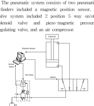
The pneumatic system consists of two pneumatic cylinders included a magnetic position sensor, a valve system included 2 position 5 way on/off solenoid valve and piezo-magnetic pressure regulating valve, and an air compressor.
Fig. 2 Scheme of pneumatic system for IDC Device
Such pneumatic system aims to control contact force by regulating the inlet pressure of cylinder chambers. In this case, the position sensor aims to just monitor stroke of piston. The cylinder chamber inlet pressure is regulated via piezo-electric pressure regulating valve (Hoerbiger, Pre-U model).
The extension and contraction process is changed by on/off solenoid valve.
This model will be verified by Matlab/Simulink simulation and an experimental apparatus.
2.2 The Dynamics Equation for Pneumatic Cylinder
The IDC device aims to control constant actuation force, the force is calculated by dynamics equation using Newton’s second law:
(1)
Where
: position of piston.
M : total mass of piston and load.
: absolute pressures, effective areas of chamber 1 and 2.
: gravitational acceleration.
: friction force.
: external load.
Generally, the motion of piston is affected by inside air pressure, external load, gravity of piston and load, friction between piston and cylinder tube.
This actuation force is generated by tuning the chamber pressure of pneumatic cylinder. The IDC device also plays a role as a damping mechanism for maintaining the contact state. The mechanism generates the compression or tensile force depending on form of external actuation.
For modeling this mechanism, the dynamics model of pneumatic cylinder’s chambers, valve system modeling and flow rate output of pressure valve are considered in following sections. The experimental apparatus has 50 mm displacement, and without external load, so this modeling will be regarded without friction and external load.
2.3 Thermodynamics Modeling of Pneumatic Cylinder’s Chambers
Following the previous researches, this section builds the thermodynamics model concerned three equations of ideal gas law, continuity equation of mass flow and the energy equation.
The ideal gas law
(2)
The mass flow rate is determined by continuity equation
(3)
So, relation P, V, m is:
(4)
On condition of process occurs without transfer of heat and temperature through all of system is remained constant. When the piston moves, the mas flow rate, volume and pressure is varied in cylinder chamber. Differentiating the equation (4):
(5)
Hence,
(6)
Where
: ideal gas constant.
: temperature.
: chamber of cylinder.
: inactive volume of cushion chamber.
: stroke of piston.
In this equation, is outlet flow rate of pressure valve, and is exhausted air flow rate.
The thermodynamic modeling of cylinder chamber 1 pressure:
(7)
2.4 Valve System Modeling
In IDC device, valve system uses a piezo-electric pressure valve for regulating the input pressure of cylinder and a Parker 2 positions 5 ways on/off solenoid valve used a switching valve for switching extension and contraction process of piston. So, this section will focus on model of pressure valve and its flow rate calculation method.
1) Modeling of Piezo-electric Pressure Regulating Valve
The pressure regulating valve consists an internal- regulator inside. This regulator aims to assure the pressure supplied to pneumatic system adapting desired set-value.
Referring from model of Yi Wang [8], this valve is proposed by using first-order model.
(8)
Where K and τ are first order system parameters.
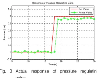
These parameters are calibrated in simulation process and will be compared with next experiments. In current experiment, the response pressure is delay about a second with respect to input pressure.
5 10 15 20 25 30
-0.2 0 0.2 0.4 0.6 0.8 1 1.2
Response of Pressure Regulating Valve
Time (s)
P res su re ( bar )
Set Value Actual Value
Fig. 3 Actual response of pressure regulating valve
2) Flow Rate of Pressure Valve
As mentioned above, the thermodynamic model is obtained from inlet flow rate and the change of
cylinder volume. The inlet flow rate is also the flow rate of pressure valve, expressed as equation [9] with the pressure of cylinder chamber1 is
and supply pressure is outlet of pressure regulating valve:
(9)
Where, is orifice area of pressure regulating valve outlet way and is flow rate coefficient (0.95). And piecewise flow function is:
(10)
The critical pressure ratio is given:
(11)
Where γ is ratio of specific heats of gas.
3. Description of Experimental Apparatus
As shown in fig. 4, the experimental apparatus includes PC, air compressor, IDC device with a load cell, I/O Module. And the I/OModule consisting of I/O block and Arduino MEGA 2560, communicated between pneumatic system and computer by Matlab/Simulink with Arduino Hardware Support Packages.
Fig. 4 Experiment Apparatus for Pneumatic System
As shown, for controlling the up-ward or down-ward of double acting cylinders, the 2 positions 5 ways on/off solenoid valve is used. And the on/off state of solenoid valve is switched by a Songle relay. The stroke of piston is measured by a magnetic position sensor, an acceleration sensor is used for measuring the orthogonal acceleration of IDC device as contacted state. A piezo-electric pressure valve is controlled by turning set value and feedbacks the actual value to PC. The set value is 0-8 VDC, is set by a 0-5V PWM module of Arduino and a first order RC circuit. The actual value is connected to Arduino by a linear voltage convert circuit for converting 1.25-6.25 VDC to 1-5 VDC. The load cell 50 kg capacity, 2.0mV/V output rate is connected the Arduino through INA125P amplifier and 100 Ohm resistance (121 Ohm as assumption). The Arduino is connected to Matlab/Simulink for receiving and transmitting signals. All data are imported into workspace.
4. Simulation Results
As abovementioned, the modeling of pneumatic system describes the linkages of the force, displacement of piston, pressure of cylinder chambers, supply pressure and flow rate of pressure valve in mathematical relations. These relations are carried out by each Matlab/Simulink block respectively. In addition, the experimental parameters are also restored on workspace of Matlab. In this simulation, the identical input signal of real apparatus is applied for simulation model, and making the comparison between the simulation modeling and experiment apparatus.
As known, the double acting cylinder can move extension and contraction, but this simulation just considers the extension of piston with respect to acting force, chamber pressure and parameters of pressure regulating valve.
The general simulation model is shown in Fig. 5, input signal of pressure valve is imported via set value of testing model. The set value is generated in two cases, case 1: a step-like signal for estimating the response of acting force and the
effect of supply pressure in single period, and case 2: a stairstep with 3 levels for testing the alternative response of acting force.
This simulation aims to evaluate the math modeling with respect to experiment processing.
Fig. 5 Simulink block diagram of operating process.
4.1 Case 1: Response of Step-like Input Pressure This case aims to describe the response of acting force on the surface when input pressure is constant.
This experiment is carried out for collecting the input and response signals of pressure regulating valve as a step-like signal and import these values into simulation program. The responses of estimated and actual value are deflected 6.5% by the inherent output of pressure regulating valve.
This time deflection is existed by the difference of Arduino delay and Simulink delay setting. As shown below, the case 1 mentions the simple task of system when the 1.8 bar input pressure is supplied. The set value is established for triggering regulation valve, the actual value is output signal of regulation valve, the magnetic position sensor detects stroke of magnetic piston and acting force is measured by load cell 50 kg 2.0 mV/V.
0 5 10 15 20 25 30 35 40 45 50
0 0.2 0.4 0.6 0.8 1 1.2 1.4 1.6 1.8 2
Time (s)
Pressure (bar)
Set Value Estimated Supply Pressure Actual Value
Fig. 6 Pressures of regulation valve with step
input.
0 5 10 15 20 25 30 35 40 45 50 0
50 100 150 200 250 300 350
Time (s)
Force (N)
Estimated Acting Force Measured Acting Force
Fig. 7 Acting force of cylinder with step input.
0 5 10 15 20 25 30 35 40 45 50
0 5 10 15 20 25 30 35 40 45 50 55
Time (s)
Position (mm)
Measured Position
Fig. 8 Stroke of piston with step input.
When pressure input is constant, the acting contact force is also constant. For testing the linearity of acting force related to pressure response of pressure regulating valve we carry out the case 2: response of system with stairstep-like pressure input signal.
4.2 Case 2: Response of System with Stairstep Signal
The principle of IDC device is the control of the constant acting force when the robot arm works on work-piece surface. To maintain such acting force, a pressure valve with built-in electronic control board is used for regulating the input pressure of pneumatic cylinder.
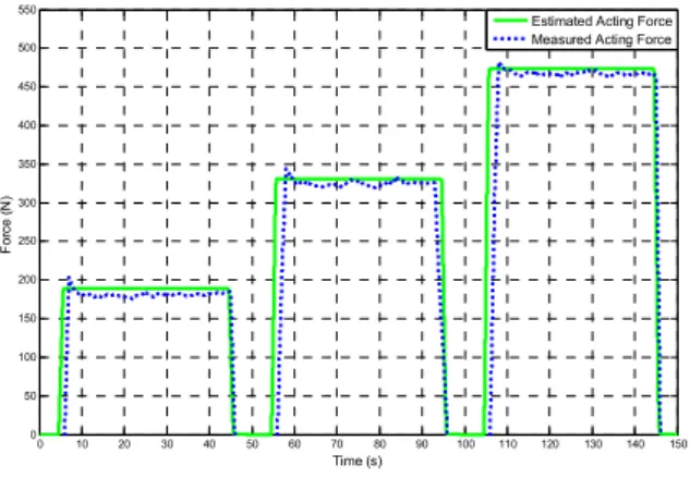
The desired value of pressure is set as stairstep signal and its actual response is shown in Fig. 9.
The acting force also responds as stairstep signal respect to supply pressure at about 1.2, 2.1 and 3.0 bar respectively, such response ratio is almost regular. The average measured value of load cell is
suitable with response of estimated acting force.
The differences are 6.0%, 6.3% and 6.3% between estimated and actual values of pressure respectively. However disadvantage that the measured data are not good as expectation, the results are variant form, because the measured signals are affected by the noises of load cell connections and the manual reactions.
0 10 20 30 40 50 60 70 80 90 100 110 120 130 140 150
0 0.5 1 1.5 2 2.5 3 3.5
Time (s)
Pressur (bar)
Set Value Estimated Supply Pressure Actual Value
Fig. 9 Pressure of regulation valve with stairstep input.
0 10 20 30 40 50 60 70 80 90 100 110 120 130 140 150
0 50 100 150 200 250 300 350 400 450 500 550
Time (s)
Force (N)
Estimated Acting Force Measured Acting Force
Fig. 10 Acting force of cylinder with stairstep input.
0 10 20 30 40 50 60 70 80 90 100 110 120 130 140 150
0 5 10 15 20 25 30 35 40 45 50 55
Time (s)
Position (mm)
Measured Position