1
A DESIGN OF SMALL DATA UTILIZATION SYSTEM FOR THE COMS
Seok-Bae Seo, In-Hoi Ku, Chi-Ho Kang, Hyun-Su Lim, and Sang-IL Ahn
Korea Aerospace Research Institute P.O. Box 113, Yuseong, Daejeon, Korea
[email protected]
ABSTRACT:COMS (Communication, Ocean, and Meteorological Satellite) will be launch at end of year 2008. For receiving of COMS LRIT, KARI (Korea Aerospace Research Institute) finished design and software realization of COMS SDUS (Small Data Utilization System). SDUS is a small station receiving LRIT data for distribute satellite image, weather information, and so on. For the future project, KARI preparing COMS MDUS (Mass Data Utilization System) that can receiving large size of data over than 2M BPS (Bit Per Seconds) data size.
KEY WORDS: COMS, SDUS, MDUS, LRIT, HRIT
1. Introduction
COMS will be launch by KARI at end of year 2008.
COMS has two type of services that SDUS and MDUS.
Both of systems consist hardware and software as con- ventional system. The hardware separated in two sys- tems - receiving system and processing system. In this paper assure that all of hardware system is working well for software system design. Here working well means SDUS receiving no error CADU that consisted 4 byte sync code (1A CF FC 1D
h) and 1024 byte data with ECC (Error Correction Code). Fig. 1 shows a rough de- sign of COMS SDUS configuration
[C.H. Kang 2004].
Fig. 1. COMS SDUS configuration
2. COMS SDUS design
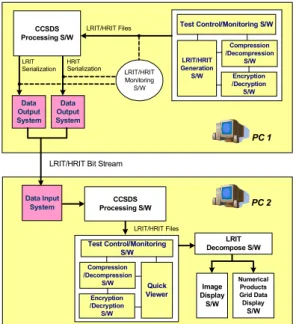
Fig. 2 shows COMS SDUS and COMS SDUS SS (Support System). PC 1 is configuration of COMS SDUS SS and PC 2 is COMS SDUS in Fig. 2. Dark boxes in Fig. 2 are H/W part, therefore assure that they will work well and explain roughly.
3. COMS SDUS Support System
Fig. 2. COMS SDUS and COMS SDUS SS
COMS SDUS SS is designed for verification for COMS SDUS that makes satellite data and LRIT bit stream in Fig. 1 by predefined schedules. As additional function, COMS SDUS SS can measure distance from GS (Ground Station) to COMS. Fig. 3 shows block dia- gram of PDR (Product Data Ranging) S/W of COMS.
PDR S/W measures distance using up and down link timestamp.
Fig.3 PDR S/W
Fig. 4 shows consist of LRIT Generation S/W of
Test Control/Monitoring S/W
LRIT/HRIT Generation S/W
Compression /Decompression
S/W
Data Output System
PC 1
LRIT/HRIT Files CCSDS
Processing S/W
LRIT HRIT
LRIT/HRIT Bit Stream Serialization
Data Input System
Test Control/Monitoring S/W
Quick Viewer
LRIT Decompose S/W
PC 2
LRIT/HRIT Files CCSDS Processing S/W Data
Output System Serialization
Encryption /Decryption S/W
Compression /Decompression
S/W Encryption /Decryption S/W
LRIT/HRIT Monitoring S/W
Image Display
S/W
Numerical Products Grid Data Display
S/W
2 COMS SDUS SS. COMS LRIT based on CGMS
LRIT/HRIT Specification. LRIT Generation S/W con- vert from received data from COMS to transportable format data via LRIT communication channel. More detailed information of COMS LIRT is explained in ‘The MSG Ground Station LRIT/HRIT Mission Specific Im- plementation’ document. COMS LRIT generation S/W has two inpus. NWP (Numerical Weather Prediction), first input data, is supplied from KMA (Korea Meteoro- logical Agency). Because of there are no images of COMS, the GOES-9’s Image data used COMS LRIT input image data instead of COMS ones.
Fig.4 LRIT Generation S/W
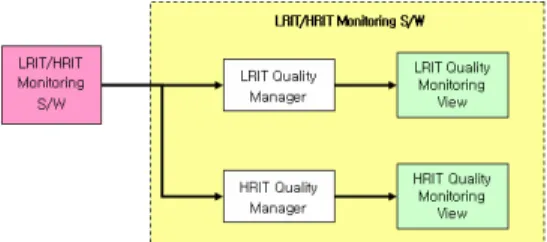
Fig. 5 explains consist of COMS LRIT monitoring S/W.
The S/W surveilles all of COMS LRIT generation proc- esses.
Fig.5 LRIT Monitoring S/W
Fig. 6 explains consist of COMS LRIT Test Con- trol/Monitoring S/W. The S/W helps to user can control- ling and monitoring test of LRIT receiving, display, and quality checking.
Fig.6 LRIT Test Controlling/Monitoring S/W Fig. 7 explains consist of COMS LRIT CCSDS proc- essing S/W. The S/W makes bit stream as CCSDS rec- ommendations for data transmit.
Fig. 8 explains consist of COMS LRIT Compres-
sion/Decompression S/W. COMS LIRT compres- sion/decompression compliances with Lossy and Loss- less JPEG standards.
Fig. 9 explains consist of COMS LRIT Encryp- tion/Decryption S/W. COMS LRIT encryp- tion/decryption compliances with DES (Data Encryption Standard).
Fig.7 LRIT CCSDS Processing S/W
Fig.8 LRIT Compression/Decompression S/W
Fig.9 LRIT Encryption/Decryption S/W
4. COMS SDUS
Fig. 10 explains detail block diagram of COMS SDUS, and Fig. 11 explains Receiver Monitoring S/W of COMS SDUS. COMS LRIT Monitoring S/W is monitoring status of COMS LRIT Receiver H/W like small size an- tenna, LNB (Low Noise Block), Demodulator, and so on.
We suppose Output data of Reciver Monitoring S/W has no error.
Fig. 12 explains consist of Receiving Schedule S/W.
Receiving Schedule of COMS LRIT is based on the
KMA Users Requirements. TM (Telemetry) is a status
data from data input system of COMS SDUS.
3 Fig.10 Detailed Block Diagram of COMS SDUS
Fig.11 LRIT Receiver Monitoring S/W
Fig.12 LRIT Receiving Scheduling S/W
Fig. 13 explains consist of COMS LRIT Quick Viewer.
The Quick Viewer displays image and qualities of cur- rent receiving LRIT data.
Fig.13 LRIT Quick Viewer
Fig. 14 explains consist of COMS LRIT Decomposition S/W. This S/W converts from received LIRT data to con- venient data for COMS LRIT data processing.
Fig.14 LRIT Decomposition S/W
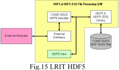
Fig. 15 explains consist of COMS LRIT HDF5 and HDF5-EOS (Earth Observing System) File Processing S/W. Here, HDF (Hierarchical Data Format) is a data format for various mass data change that developed by the NCSA (National Center for Supercomputing Appli- cations)
[NCSA 2005].
Fig.15 LRIT HDF5
Fig. 16 explains consist of COMS LRIT Geographical Location S/W. The S/W supports transform between pixel coordinate and geodetic coordinate with each other.
Fig.16 LRIT Geographical Location S/W Fig. 17 explains consist of COMS LRIT Image Display S/W. So COMS image size is large, that the S/W needed supporting of partial image processing.
Fig.17 LRIT Image Display S/W
Fig. 18 explains consist of COMS Image Processing
S/W. The S/W has function of enhancement, filtering,
zooming, band combination, and so on for COMS LRIT
Images.
4 Fig.18 LRIT Image Processing S/W
Fig. 19 explains consist of COMS LRIT Image Genera- tion S/W. The S/W can save to BMP, JPEG, and TIFF image format for partial or whole image from COMS SDUS S/W.
Fig.19 LRIT Image Generation S/W
Fig. 20 explains consist of COMS LRIT Map Projec- tion S/W. The S/W supports transform among polar- stereographic, Lamber conformal conic, Mercator, per- spective, and normalized geostationary with one another.
Fig.20 LRIT Map Projection S/W
Fig. 21 explains consist of COMS LRIT Meteoeorologi- cal Product Display S/W. The S/W supports display like plotting, thermodynamic display, cross-section, stability index calculation and display, and objective analysis to produce grid values.
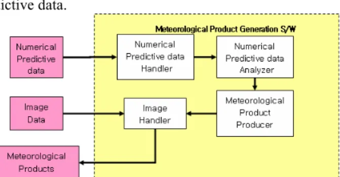
Fig.21 LRIT Meteorological Product Display S/W Fig. 22 explains consist of COMS LRIT Numerical
Product Generation S/W. The S/W makes meteorological products using COMS LRIT images and numerical pre- dictive data.
Fig.22 LRIT Numerical Product Generation S/W Fig. 23 explains consist of COMS LRIT Numerical Products Grid Data Display S/W. The S/W displays nu- merical products grid data and overlays plotting, contour, and so on.
Fig.23 LRIT Numerical Products Grid Data Display S/W Fig. 24 explains consist of COMS LRIT Meteorological Observation Data and Administration Message Display S/W. The S/W supports observation and administration of H/W like small size antenna, LNB, demodulator, and so on.
Fig.24 LRIT Meteorological Observation Data and Ad- ministration Message Display S/W
5. Conclusions
This paper explains current states of COMS SDUS de- sign researching in KARI. We expect that SDUS will carry out as good small data utilization System for COMS after COMS launching.
References
[C.H. Kang 2004] The Global Perspective Plane Image Generation using the GOES-9 Satellite Images, KARI Technical Memo, KOREA.
[NCSA 2005] NCSA HDF-EOS Project Homepage http://hdf.ncsa.uiuc.edu/hdfeos.html