• 검색 결과가 없습니다.

Recent Progress in Layer-by-layer Assembly of Nanomaterials for Electrochemical Energy Storage Applications

N/A
N/A
Protected

Academic year: 2021

Share "Recent Progress in Layer-by-layer Assembly of Nanomaterials for Electrochemical Energy Storage Applications"

Copied!
10
0
0

로드 중.... (전체 텍스트 보기)

전체 글

(1)

Vol. 17, No. 3, 2014, 139-148

http://dx.doi.org/10.5229/JKES.2014.17.3.139

− 139 −

Recent Progress in Layer-by-layer Assembly of Nanomaterials for Electrochemical Energy Storage Applications

Sung Yeol Kim*

School of Mechanical Engineering, Kyungpook National University, Daegu 702-701 Korea (Received July 22, 2014 : Accepted August 7, 2014)

Abstract : Electrochemical energy-storage devices such as batteries and supercapacitors are important components in emerging portable electronic device, electric vehicle, and clean energy storage and supply technologies. This review describes recent progress in the development of nanostructured electrodes, the main component of the electrochemical energy-storage device, prepared by layer-by-layer (LbL) electrostatic assembly. Major advantages associated with, and challenges to, the fabrication of LbL electrodes, as well as the future outlook for expanding the application of LbL techniques, are discussed.

Keywords : Layer-by-Layer assembly, nanomaterials, energy storage, battery, supercapacitor

1. Introduction

Layer-by-layer (LbL) methods are simple but ver- satile bottom-up film fabrication techniques based on the sequential adsorption of positively and nega- tively charged materials onto a substrate.

1)

A wide range of materials including organic molecules, inor- ganic colloidal particles, carbon nanomaterials, and polymers have been assembled using LbL processes, and such devices have been applied to a wide vari- ety of biomedical, optical, environmental, and energy conversion and storage technologies.

2)

LbL methods have been used to fabricate the main components in electrochemical energy conversion and storage devices such as fuel-cell membranes and electrodes for Li-ion batteries and supercapacitors.

3,4)

Recently, interest in developing LbL-film electrodes for electrochemical storage has expanded with the recent development of novel nanomaterials with attractive energy-storage properties. LbL methods enable the fabrication of a variety of novel electrodes through the selective and synergistic combination of these nanomaterials, since the film composition and structure can be easily tuned to obtain desirable traits such as high power and energy density. Our

focus in this review is on LbL-film electrodes for Li-ion batteries, which store electrochemical energy by Li-ion intercalation, and supercapacitors, which employ surface storage mechanisms (i.e. double- layer capacitance or pseudo-capacitance). Readers interested in the use of LbL-deposited films in fuel cell electrode/membrane applications are referred to a recent review paper on that topic.

5)

Lithium intercalation is slow compared to sur- face-charge storage mechanisms because it requires volume changes in the electrodes and accommoda- tion of the associated extra strain energy. How- ever, it enables the utilization of the entire volume of active material for charge storage and, there- fore, provides high energy densities. Fig. 1 shows a Ragone plot (i.e. the relationship between energy density and power density) indicating the capabili- ties of these electrochemical storage devices along- side those of fuel cells and internal combustion engines. As expected given their respective charge- storage mechanisms, Li-ion batteries possess high energy density while supercapacitors have high power density. The general research goal in these fields is to develop higher energy, higher power electrochemi- cal devices, as indicated by the red arrow.

This review begins with an overview of the basic principles and benefits of the LbL process. Next,

*E-mail: [email protected]

(2)

recent LbL electrode systems for energy storage applications are surveyed, focusing on their advan- tages and limitations in terms of performance and stability. In particular, LbL electrode systems incor- porating carbon nanomaterials, or two or more dif- ferent nanomaterials, are introduced. Conventional LbL fabrication methods and their limitations are introduced, and an alternative technique that extends LbL methods to the rapid fabrication of thick elec- trodes with large areas is demonstrated. Finally, future directions for the technique are anticipated.

2. Basic principles and general advantages of LbL processes

The LbL process is a simple but versatile film fabrication technique in which a variety of materials can be utilized and the film morphology, including structure and thickness, can be easily controlled.

The essential driving force behind LbL assembly is the electrostatic attraction between oppositely charged molecules in each layer. Fig. 2 is a sche- matic illustrating the deposition of charged multi- walled carbon nanotubes (MWNTs) via a conven- tional “dip-LbL” process: First, a negatively charged substrate is dipped into a solution that contains positively charged MWNTs for a few tens of min- utes until the adsorption/desorption equilibrium is reached. Then, the substrate is dipped into a wash- ing solution to remove the excess carbon nanotubes from the surface. Finally, the substrate is dipped into a solution of negatively charged MWNTs to complete the first bi-layer of oppositely charged MWNTs. These processes can be repeated until the desired number of bi-layers/film thickness is obtained. In this example, the species of interest (i.e. carbon nanotubes) has to be functionalized to obtain the charged surface groups necessary for the LbL method. Besides electrostatic forces, hydrogen Fig. 1. Ragone plot showing the capabilities of different

energy storage and conversion technologies.

Fig. 2. Fabrication of a multi-layer carbon nanotube film via the dip-LbL process.

(3)

bonding and hydrophobic interactions have also been used to assemble LbL films.

2)

Fig. 3a shows the zeta potential of the function- alized MWNTs as a function of the pH, indicating that the number of surface charged groups can be easily controlled via the pH. The pH changes the density of charged species in each layer; this affects the intensity of the electrostatic interactions and, consequently, affects the film growth and structure (Fig. 3b and c). Other advantages of LbL processes include their low cost and environmental friendliness because neither sophisticated equipment nor toxic organic solvents are required.

2

3. Application of LbL films in electrochemical energy storage

Although only a few years have passed since the first reports of the use of LbL electrodes in energy storage applications,

7)

a general design scheme (or direction) has been established to achieve both high energy and high power. Traditional battery electrodes

are composed of binder, carbon black (a conductor), and the active materials. In contrast to these conventional electrodes, LbL electrodes are free of binders (e.g. polyvinylidene fluoride), which often prevent ionic or electronic transport or decrease charge storage because the binding forces between the particles are determined by the electrostatic interactions of charged functional groups. Even without binders, LbL-film electrodes exhibit good mechanical stability, especially after heat treatments that convert the ionic interactions into covalent amide bonds. When deposited on flexible PDMS, LbL films showed excellent flexibility with good mechanical stability, which may be useful in the development of flexible battery electrodes.

7)

3.1. Carbon-nanomaterial-based LbL electrodes

Among the many nanomaterials available, the key

examples in the design of LbL-film electrodes are the

carbon-based nanomaterials, such as carbon nanotubes

and graphene oxides.

7,8)

These nanomaterials serve as

both an electron conductor (similar to carbon black)

Fig. 3. (a) The zeta potential of charged MWNTs as a function of pH, (b) LbL film thickness as a function of number of

deposited bi-layers, and (c, d) atomic force microscopy images of LbL MWNT films fabricated at different pH levels. All

figures are adopted from refs. 6, 7.

(4)

and as a binder, given their charged functional groups. Lee et al.

9)

reported that the functional groups used for LbL assembly provide additional charge storage mechanisms: negatively charged carboxyl groups in the acid-treated carbon nanotubes undergo faradaic reactions like

for lithium-ion containing electrolytes. These LbL- MWNT electrodes show double the gravimetric capacitance of pristine MWNTs, suggesting a considerable contribution from the functional groups.

It was also shown that the LbL MWNTs possess excellent stability; they exhibited no capacity loss after 2500 cycles.

9)

Another emerging carbon nanomaterial used in LbL assembly is graphene. Graphene is a two-dimen- sional high-surface-area carbon network with excel- lent electrical, mechanical, and chemical properties.

10)

Because of these attractive features, graphene has recently been employed an electrode material.

8,11)

Similar to carbon nanotube, the graphene LBL tech- nique requires the use of functionalized graphene or graphene oxide (GO), which is negatively charged with carboxylic groups. Byeon et al. reported that LbL electrodes composed of MWNTs and reduced GO possessed higher gravimetric and volumetric capacitances than those of LbL MWNTs electrodes.

8)

3.2. LbL electrodes with non-carbonaceous nanomaterials

Although the exclusively carbon-based LbL elec- trodes are promising, further improvements can be made by pairing carbon nanomaterials with other high-energy nanomaterials. For example, the energy density of LbL electrodes can be increased when materials such as conducting polymers and metal- oxide particles are incorporated into the carbon nanomaterial network. Mixing with highly conduc- tive carbon nanomaterials is essential to achieve high performance. This is because most of the high-energy metal oxide particles have low elec- tronic conductivity (10

−1

10

−4

S/cm) and low Li- ion diffusion coefficients, resulting in low-power electrodes with limited accessible energy, even at low current rates. Also note that decreasing the characteristic size of the high-energy material to the nanometer scale is vital because the overall diffu- sion coefficient is inversely proportional to the

square of characteristic length scale.

Recent research shows that LbL methods are effective tools for fabricating hybrid electrodes with an interconnected network of carbon nanomaterials and high-energy nanomaterials without aggregation.

For example, high-energy metal-oxide nanoparticles such as TiO

2

, MoO

2

, and SnO

2

have been paired with both carbon nanotubes and GO for use as anode materials (see Fig. 4).

5,12,13)

SEM and TEM images reveal the LbL method resulted in sheets of graphene with well distributed SnO

2

particles with- out apparent aggregation. In general, metal-oxide nanoparticles could be assembled with carbon nano- materials without aggregation, providing excellent power and energy capacity.

XPS or thermogravimetric analysis can be used to determine the relative composition of metal oxides and carbon nanomaterials. A thermogravimet- ric scan of a LbL-TiO

2

/MWNT material whose TiO

2

loading is ~50% is shown in Fig. 5a. Even with the high TiO

2

loading, electronic conductivity is relatively high in the LbL-film structure. Fig. 5b compares the electronic conductivity of an LbL- TiO

2

/MWNT film with that of a drop-cast film as a function of film thickness. The conductivity of the LbL-TiO

2

/MWNT films increase linearly with Li

+

+ CO LiCO

Fig. 4. (a) Schematic illustration (left) and labeled TEM

image (right) of LbL assemblies of MWNTs and TiO

2

metal-oxide nanoparticles (adopted from ref. 12); (b, c)

SEM and (d, e) TEM images of SnO

x

/graphene materials

(adopted from ref. 13).

(5)

increasing thickness, presumably due to the enhanced percolation of MWNTs with increasing thickness, and eventually saturates. Their conductivity was as high as 5.2 S/cm, which is comparable to LbL electrodes comprised of MWNTs exclusively. This result demonstrates that the conductivity arises from the interpenetrating MWNT network, and that the con- ductivity is not significantly affected by the addition of TiO

2

nanoparticles (< 8 nm) when the LbL method is used for fabrication. In contrast, the conductivity of the drop-cast TiO

2

/MWNT films was 4 times lower than that of the LbL films, due to the aggregation of the nanomaterials, showing the superiority of the LbL method for assembling nanomaterials.

12)

This LbL-TiO2/MWNT film was used as an anode in a Li-ion battery, which provided 150 mA/g at a current rate of 0.1 A/g with a stability of over 200 cycles. Unlike the monolithic LbL-carbon elec-

trodes, the TiO

2

-composite LbL electrode exhibits a distinct potential plateau at ~1.8 V (vs. Li), which originates from the faradaic reaction of the metal oxide and lithium. This effect is advantageous to battery operation, where a constant potential is fre- quently required.

The conducting polymer polyaniline (PANI) has been u se d a s a n L b L - c a t h o d e m a te r ia l i n L i - i o n batteries,

11,14,15)

and PANI nanofibers and MWNTs have been successfully mixed using the LbL method.

Similar to metal-oxide particles composited with MWNTs, the morphologies of the LbL-PANI/MWNT films showed that the individual identities of the materials were retained, but the physicochemical properties improved overall due to the cross-linked network.

14)

The LbL-PANI/MWNT film provided a higher volumetric power and energy density than the LbL-MWNT film. PANI was also paired with graphene to make LbL-PANI/graphene film electrodes with capacitances as high as 350 F/g.

11)

When PANI was included in LbL electrodes, it was shown that the carbon nanomaterial is not always needed for its high conductivity. In this case, the percolation network of the PANI nanomaterial serves as a pathway for electron transfer and as an active material for charge storage.

16)

Therefore, the different high-energy material can be incorporated with PANI. Shao et al. showed that V

2

O

5

can be composited with PANI to make a cathode material exhibiting a volumetric capacity of 264 mAh/cm

3

.

17)

The same group incorporated a PANI complex, polyaniline:poly(2-acrylamido-2-methyl-1-propane- s u l f o n i c a c id ) ( PA N I : PA A M P S A ) i n t o L b L electrodes

18)

and investigated the performance of different LbL electrodes made of PANI assembled with electrochemically inactive polymers. They tested and compared three different PANI-based LbL electrodes comprised of PANI/PAAMPSA, PANI/PANI:PAAMPSA, and linear poly(ethylen- imine) /PANI:PAAMPSA in terms of film growth, charge storage, and cycling stability. Each LbL-film composite had unique characteristics. For example, the linear poly(ethylenimine) /PANI:PAAMPSA film shows much higher cycling stability but lower charge storage capacity due to the lower content of PANI and the linear poly(ethylenimine) serving as a barrier to charge transport and access.

Fig. 5. (a) Thermogravimetric scan of a LbL-TiO

2

/

MWNT (n = 60) electrode, and (b) electronic conductivity

of LbL-TiO

2

/MWNT electrodes and comparable drop-

cast electrodes. (adopted from ref. 12).

(6)

3.3 Post-fabrication treatment

In some cases, it is beneficial to apply a post- fabrication treatment to tune the film characteristics.

Especially when carbon nanomaterials are used, the reduction of their charged functional groups (required for the electrostatic film assembly) can increase the film conductivity.

7,8,14)

It was shown that heat treatment of LbL films made of carbon nanomaterials (MWNT or GO) can significantly improve their conductivity. Fig. 4a shows that post- fabrication heat treatment at 120

o

C with hydrazine (a reducing agent) can increase sheet resistance by a factor of 6 and results in enhanced electrochemi- cal activity.

8)

These results can be attributed to the reduction of functional groups and the formation of amide bonds between the amine and COO − termi- nated functional groups. This also allows intimate contact and prevents delamination of the electrode material. Note that these LbL-film electrodes pos- sessed a high packing density of 70%, which is

among the highest for nanostructured-carbon elec- trodes and resulted in a high volumetric capacitance (130-150 F/cm

3

). Further reduction of LbL films using hydrogen gas and heat treatment at higher temperatures is possible but can result in a decrease in energy and power density. This can be attributed to a decrease in the surface area and pore size, limiting ion transport through the film.

It was also shown that heat treatment can result in better-defined nanopores and better interconnec- tivity in LbL-MWNT/PANI films, allowing for higher performance.

14)

In addition to the direct assembly of different nanomaterials during LbL fab- rication mentioned earlier, LbL electrodes of carbon nanomaterials can be decorated with other nanopar- ticles such as MnO

2

by post-treatment with electro- less redox deposition.

19)

The loading of oxide nanoparticles can be controlled easily by controlling the dipping time of the carbonaceous LbL elec- trodes in permanganate solution.

Fig. 6. (a) Sheet resistance and (b) electronic conductivity of the LbL-MWNT/GO films and hydrazine-treated LbL-

MWNT/GO films (“MWCNT/CRG”) as a function of the number of bi-layers. (c) ATR-FTIR plots of LBL-MWNT/GO

and MWNT/CRG films. The grey window indicates the 1500-1750 cm

1

wavenumber range where the peaks associated

with amide bonds occur. (d) XPS spectra of LBL-MWNT/GO and MWNT/CRG films in the N 1s binding-energy

regions. All figures are adopted from ref. 8.

(7)

3.4 Advantages and Limitations

The main advantages of LbL film electrodes can be summarized as follows: First, they are binderless nanostructured electrodes with high power, high energy, and good stability. Second, their thickness and microstructure can be easily and precisely con- trolled, eliminating aggregation effects. Third, vari- ous combinations of energy storage materials can be combined, and their properties tuned, during LbL fabrication or post-fabrication processing.

However, there are some limitations on the per- formance of LbL-film electrodes and LbL fabrica- tion methods. The LbL electrodes introduced so far have a typical thickness of a few hundreds nanom- eters, a thickness useful for applications in micro- scopic thin-film batteries; electrochemical capacitors for thin-film devices; and other microsystems such as on-chip power supplies, storage for energy-har- vesting systems, and sensors. The primary drawback of the conventional LbL technique is its lengthy processing times, which would limit the applica- tion of LbL electrodes in load leveling, electric vehicles, and circumstances where the rapid fabrica- tion of scaled-up electrodes are required.

3)

Another drawback of LbL electrodes is their high polariza- tion levels (~30% energy loss during charging and discharging).

9)

For exclusively carbonaceous LbL electrodes, the functionalization of carbon surfaces with organic molecules has been proposed, which would permit the potential profile to be tuned and reduce the voltage polarization during charge and discharge.

9)

The optimization of cell design may further mitigate the polarization problem by reduc- ing the contact resistance and/or mass-transport lim- itations in the electrolyte.

20)

4. Future outlook

Most LbL-film electrodes for energy research reported in the literature were fabricated by the dip-LbL method. Because of the lengthy processing times involved in this method, it can take a couple of days to construct films a few micrometers thick.

For example, it takes ~100 hours to fabricate a three-micrometer–thick LbL-carbon nanotube films for use in an Li-ion battery.

9)

Fig. 7 shows alternative LbL methods available such as spray- and spin-based techniques.

10)

Compared to dip-LbL, these new methods have shorter processing times (on the order of a few seconds vs. a few tens of minutes for dip LbL) and can efficiently deposit an LbL film of similar quality. These processes are especially useful in the development of electrodes for energy-storage applications, where the thickness of the electrode has to be efficiently and quickly controlled. The required thickness depends on the application; a few micrometers for micro-scale devices and 10 to 100 microns for many commer- cial applications.

Recently, Kim et al. reported the rapid fabrication of LbL-MWNT electrodes using a modified spray- LbL method. It was shown that spraying MWNTs in a LbL fashion onto a flat substrate did not produce good film growth, a result that was inconsistent with spray-LbL films composed of polymer electrolytes (e.g. LPEI, PAA).

6)

This was attributed to the fact that, in the spray-LbL method, additional hydrodynamic forces act upon the high- aspect-ratio nanotubes, pulling them away from the substrate and impeding the development of intimate contact between the incoming charged species and

Fig. 7. Schematic diagrams showing different techniques for fabricating multilayer films. (a) The conventional dip-LbL

method, (b) the spray-LbL method, and (c) the spin-LbL method.(figures adopted from ref. 10).

(8)

the substrate. Also, the short processing times for spray LbL (~15 sec) might not be enough to deposit mechanically stiff MWNTs, since their rearrangement or deformation under electrostatic interactions is lim ited compared to the soft polymers. To overcome these challenges, deposition on porous carbon substrates and the application of a vacuum across the film thickness were introduced to enhance the surface interactions, capillary forces, and the physical entrapment in the pores. This new method resulted in a linear growth of LbL-MWNT electrodes with a 600-fold decrease in their fabrication time. These techniques are detailed in Fig.

8; the sharp differences in the “energy / processing time” data in Fig. 8(d) indicate the tremendous improvement achieved. The spray-LbL MWNT films exhibited similar morphologies and electrochemical performances as the equivalent dip-LbL MWNT films. Using these new LbL methods, it was possible to rapidly (< 1 h) fabricate LbL-film electrodes with the highest energy capacity per unit area (up to 300 mWh/cm

2

at 0.4 mW/cm

2

) to date, demonstrating

the promise of these new methods for extending the application of LbL techniques to general electrode fabrication. However, to fully utilize these techniques, further investigations on the incorporation of different nanomaterials and substrates (e.g., substrates with different porosity and flexibility), optimization of spray conditions (e.g. spray distance, pressure, and pH), and scalability of electrode size are necessary.

The performance of energy storage electrodes at high power or rapid charging/discharging rates depends not only on the electrode material but also on the electrode structure. It was shown that vari- ous 3D electrode structures enable delivery of high power while maintaining high energies.

21)

Because LbL methods can be adapted to conformally coat a variety of 2D or 3D substrates with different nano- materials, they will be useful for fabricating novel electrodes with 3D structures. One way to fabri- cate 3D LbL electrodes is by depositing LbL assemblies on an electronically conductive 3D struc- tured substrate. Another method uses soft tem- plates to form 3D-structured nanomaterials, as

Fig. 8. (a) Schematic diagram showing the spray-LbL deposition of carbon nanotubes on a porous substrate under

vacuum. (b) Optical and SEM images of spray-LbL films of carbon nanotubes on carbon paper. (c, d) Ragone plots of

LbL-carbon nanotube films in terms of gravimetric and areal quantities, respectively.

(9)

shown in Fig. 9. The first reported fabrication of a 3D LbL-film electrode for energy storage employed PSS a template to construct a hollow sphere con- sisting of the LbL assembly of PANI and carbon black. This supercapacitor electrode showed a high capacitance of 532 F/g in 1 M H

2

SO

4

.

22)

However, this electrode should have a very low volumetric capacitance since most of its electrode volume is empty. Future research will utilize a variety of tem- plate materials and nanomaterials to make novel 3D electrodes that more effectively utilize the space available. Systematic studies on different combina- tions of electrode structure and nanomaterial will provide insight into the optimal strategies for differ- ent energy storage applications.

5. Summary

Nanostructured LbL-deposited electrodes possess many attractive features for electrochemical energy storage systems including high energy density, power density, and stability. These benefits are the result of the unique features of the electrodes: they are binder-free and possess a highly interconnected porous network of high surface-area nanomaterials.

Another advantage of LbL electrodes is that their thickness and composition can be precisely and eas- ily controlled, allowing for equally easy control of their performance. LbL-deposited electrodes of

exclusively carbonaceous nanomaterials were been developed first, and recently high-energy nanomate- rials incorporating metal oxides and conducting polymers together with carbon nanomaterials have further enhanced the performance of the electrodes.

Scalability is the major limitation of LbL processes, though recent reports on modified spray-LbL methods have shown some promise for the rapid fabrication of large, thick electrodes. However, developing large- scale, cost-effective LbL processes still requires considerable research. It is anticipated that the con- formal deposition capabilities of LbL techniques will be employed in the fabrication of 3D elec- trodes, and this will provide us a useful way of improving energy and power characteristics.

Acknowledgements

This research was supported by the Kyungpook National University Research Fund, 2013.

References

1. G. Decher, Science, 277, 1232-1237 (1997).

2. P. T. Hammond, Curr Opin Colloid In, 4, 430-442 (1999).

3. S. W. Lee, B. M. Gallant, H. R. Byon, P. T. Hammond, and Y. Shao-Horn, Energy Environ. Sci., 4, 1972-1985 (2011).

4. Y. Xiang, S. F. Lu, and S. P. Jiang, Chem. Soc. Rev., 41, 7291-7321 (2012).

5. F. F. Xia, X. L. Hu, Y. M. Sun, W. Luo, and Y. H. Huang, Nanoscale, 4, 4707-4711 (2012).

6. S. Y. Kim, J. Hong, R. Kavian, S. W. Lee, M. N. Hyder, Y. Shao-Horn, and P. T. Hammond, Energy Environ. Sci., 6, 888-897 (2013).

7. S. W. Lee, B. S. Kim, S. Chen, Y. Shao-Horn, and P. T.

Hammond, J. Am Chem Soc., 131, 671-679 (2009).

8. H. R. Byon, S. W. Lee, S. Chen, P. T. Hammond, and Y.

Shao-Horn, Carbon, 49, 457-467 (2011).

9. S. W. Lee, N. Yabuuchi, B. M. Gallant, S. Chen, B. S.

Kim, P. T. Hammond, and Y. Shao-Horn, Nat Nanotech- nol., 5, 531-537 (2010).

10. J. Hong, J. Y. Han, H. Yoon, P. Joo, T. Lee, E. Seo, K.

Char, and B. S. Kim, Nanoscale, 3, 4515-4531 (2011).

11. T. Lee, T. Yun, B. Park, B. Sharma, H. K. Song, and B.

S. Kim, J. Mater Chem., 22, 21092-21099 (2012).

12. M. N. Hyder, B. M. Gallant, N. J. Shah, Y. Shao-Horn, and P. T. Hammond, Nano Lett., 13, 4610-4619 (2013).

13. J. Y. Jingjing Tang, Limin Zhou, Jing Xie, Guanghui Chena, and Xiangyang Zhou, J. Mater. Chem. A, 2, 6292-6295 (2014).

14. M. N. Hyder, S. W. Lee, F. C. Cebeci, D. J. Schmidt, Y.

Fig. 9. TEM images of (a) PANI, (b) carbon black, (d)

PSS microspheres, and (e, f) hollow LbL-PANI/carbon

black microspheres ( n = 4) (adopted from ref. 22).

(10)

5, 8552- 8561 (2011).

15. J. W. Jeon, J. O'Neal, L. Shao, and J. L. Lutkenhaus, ACS Appl. Mater. Interfaces, 5, 10127-10136 (2013).

16. J. F. Mike and J. L. Lutkenhaus, J. Polym. Sci. Pt. B- Polym. Phys., 51, 468-480 (2013).

17. L. Shao, J. W. Jeon, and J. L. Lutkenhaus, Chem. Mat., 24, 181-189 (2012).

18. L. Shao, J. W. Jeon, and J. L. Lutkenhaus, J. Mater.

Chem. A, 1, 7648-7656 (2013).

Shao-Horn, Acs Nano, 4, 3889-3896 (2010).

20. A. Nyman, T. G. Zavalis, R. Elger, M. Behm, and G.

Lindbergh, J. Electrochem Soc., 157, A1236-A1246 (2010).

21. H. G. Zhang, X. D. Yu, and P. V. Braun, Nat Nanotech- nol., 6, 277-281 (2011).

22. B. Mu, P. Liu, and A. Q. Wang, Electrochim. Acta., 88,

177-183 (2013).

수치

Fig. 2. Fabrication of a multi-layer carbon nanotube film via the dip-LbL process.
Fig. 3a shows the zeta potential of the function- function-alized MWNTs as a function of the pH, indicating that the number of surface charged groups can be easily controlled via the pH
Fig. 6. (a) Sheet resistance and (b) electronic conductivity of the LbL-MWNT/GO films and hydrazine-treated LbL- LbL-MWNT/GO films (“MWCNT/CRG”) as a function of the number of bi-layers
Fig. 7. Schematic diagrams showing different techniques for fabricating multilayer films
+3

참조

관련 문서

3) A comparison of the stoichiometric equation with the experimental kinetic expression can suggest whether or not we are dealing with an elementary reaction. 4) If one

Module Initialization function block is used in a program with setting of A/D conversion module located base number, slot number of located module on base, specifying a

It considers the energy use of the different components that are involved in the distribution and viewing of video content: data centres and content delivery networks

After first field tests, we expect electric passenger drones or eVTOL aircraft (short for electric vertical take-off and landing) to start providing commercial mobility

1 John Owen, Justification by Faith Alone, in The Works of John Owen, ed. John Bolt, trans. Scott Clark, &#34;Do This and Live: Christ's Active Obedience as the

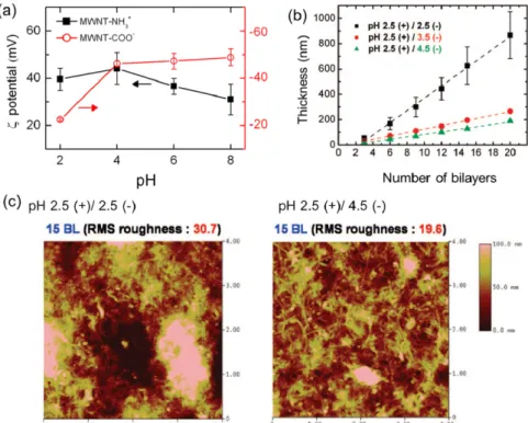
The thickness of crose-sectional is decreased, the roughness of top surface is decreased as a function of the oxygen gas flow rate was increased.. The structure and

Page 22 Figure 4 Storage moduli( E’ ) at 100 and 200 °C of PLA blends with Li-SPS and Na-SPS ionomers as a function of weight % of the ionomer in blends, measured at 1 Hz..

• Apply the principle of work and energy between the initial position and the point at which the spring is fully compressed and the velocity is zero. The only unknown in