Numerical Study on Three-Dimensional Solid-Liquid Flow for the Optimum Design of Lifting Pump
Dong-Kil Lee
1),2)* and Won-Mo Sung
1)심해저 망간단괴 양광펌프의 최적설계를 위한 차원 고 액 3 - 전산유동해석 연구
이동길* ․ 성원모
요 약 : 심해저 양광시스템의 핵심부품인 양광펌프의 최적설계를 위해 차원 고체 액체 상 유동에 대한 전산해3 - 2
석을 수행하였다 비정상상태 전산해석을 통해 두 가지 형태의 펌프의 입구부 형상에 대한 분석을 수행하였다. .
고체입자와 해수의 상호작용과 유동해석을 위해 오일러리안 해석기법을 적용하였다 그 결과 펌프 내부의 망간.
유동경향분석과 입출구부분의 망간체적점유율 전압차 등의 분석결과를 산출하였고 이를 통하여 양광펌프의 입,
구부 형상을 결정할 수 있었다.
주요어 : 양광펌프 최적 입구부형상, , 2상전산해석 오일러리안 기법,
Abstract : Three dimensional two phase numerical analysis was performed to understand the flow characteristics of solid-liquid mixtures in lifting pipes and to enhance the performance of the lifting pump for the mining tests at the offshore areas. The analysis deduced an optimum inlet area design through pump performance estimation where numerical analysis comparison was conducted for two models which have different inlet shapes according to the change of time. The Eulerian method was used to consider the movement and inter-phase transfer between flow and particles. As a result, the optimum inlet shape was determined by analyzing flow patterns in the lift pump and the total pressure difference between the inlet and outlet of the lift pump.
Key words :Lift pump, Optimum inlet shape, Two phase numerical analysis, Eulerian method Vol. 43, No. 3 (2006) pp. 206-212
Introduction
The deep sea floor could be thought as the last treasury of mineral resources to be left for mankind.
The advanced countries have already driven forward actively the development of deep sea mineral resources in preparation for the on-land mineral resource exhaustion since 1960's. Especially, the successful development of deep sea manganese nodules requires developing ex- ploration, mining and transfer technologies simultaneously,
among which mining technology includes collecting and lifting technologies of the manganese nodules (Chung, 1994). Lifting system is crucial to achieve the success of the deep-sea mining project, by which manganese nodules are conveyed from the seafloor to the mining ship and can be classified into the hydraulic pumping system and the air lift system according to the fluid dredging type, the continuous line buckets system of the mechanical type and the modular marine mining automation system. Among the lifting methods, it proved that hydraulic pumping and air lift systems were feasible technically (Yoon et al., 2001; Yoon et al., 2003).
Hydraulic pumping system is two-phase lifting tech- nology of solid and liquid. Among the sub systems, a lifting pump is the most important. When fine particles of nodules accumulate in the pump impeller, the pump efficiency decreases and serves as a factor that diminishes
년 월 일 접수 년 월 일 채택
2006 3 9 , 2006 6 8
한양대학교 1)
한국지질자원연구원 2)
*Corresponding Author 이동길( ) E-mail; [email protected]
Address; 30 Gajeong-dong, Yuseong-gu, Daejeon 305-350, Korea
연구논문
the whole lifting efficiency. So the optimum design of the pump is required to consider the basic physical properties of nodules such as size, shape, density or solid concentration of slurry, etc.
Multi-phase flow denotes the simultaneous motion of two or more phases. General classifications of two-phase flow problems are based on the constituents (Ishii, 1975):
gas-solid, gas-liquid, solid-liquid, and two immiscible liquids as well as on the flow pattern: separated and dispersed flows. For the modeling of the multi-phase flow, two approaches of Lagrangian and Eulerian were focused. However, the approach of explicit droplet integration of Lagrangian suffers when scaling to large three-dimensional flow situations. For this reason, development in the past years has begun to focus on Eulerian schemes for simulating two-phase flow (Gerber and Kermani, 2004).
In the study, we have performed solid-liquid two- phase flow simulations to improve the design of a prototype pump for a sea test. As a CFD (Compu- tational Fluid Dynamics) model, FLUENT was used with Eulerian multi-phase modeling method to consider the flow of solid particles and sea water because it could be applied efficiently to the both cases of dispersed or stratified flows. From the results, the inlet area of the pump has been modified.
Multi-phase Modeling for Solid-liquid Two-phase flow
Eulerian multi-phase flow analysis
As mentioned before, modeling method of two phase solid-liquid flow can be changed according to solid distribution and mass, momentum and energy exchange between solid and liquid, in which case the Eulerian method and Lagrangian method are most widely applied.
In the Lagrangian view-point, attention is focused on a specific piece of fluid or particles rather than a region of space, but the Eulerian viewpoint is fixed in space.
In general, the two methods should be appropriately mixed and applied for simulation analysis of solid and liquid such as continuum-continuum(Eulerian-Eulerian) and Eulerian-Lagrangian numerical simulation(Patankar, 2002; Chiesa et al., 2005).
In the Eulerian multi-phase model, the phases are
treated as interpenetrating continua coexisting in the flow domain. Comparing the Eulerian multi-phase with the Lagrangian two-phase model, the former has the computational advantage such as time where the phases are widely dispersed and when the dispersed phase volume fraction is high(Patankar and Joseph, 2001). In FLUENT, the Eulerian model is the most complex of the multiphase models. It solves a set of n momentum and continuity equations for each phase. Coupling is achieved through the pressure and interphase exchange coefficients. The manner in which this coupling is handled depends upon the type of phases involved;
granular flows, the properties are obtained from app- lication of kinetic theory.
For the Eulerian modeling of solid-liquid mixture, the CFD model is based on the following: A single pressure is shared by all phases. Momentum and continuity equations are solved for each phase. Also several inter- phase drag coefficient functions are available, which are appropriate for various types of multiphase regimes.
The governing equations and drag coefficient functions are as follows:
Conservation of mass:
The continuity equation for phase q is
∇‧
(1)where, and are the volume fraction and density,
is the velocity of phase q, and characterizes the mass transfer rate between p and q phases.
Momentum equation:
The momentum balance for phase q is
∇‧
∇ ∇ ‧
(2) where, is the q phase stress-strain tensor.
Here and are an external body force and a lift force, is a virtual mass force, is an interaction force between phases, and p is the pressure
shared by all phases.
Eq. (2) must be closed with appropriate expressions for the inter-phase force . This force depends on the friction, pressure, cohesion, and the other effects and that is defined as in equation (3).
(3)
where is the inter-phase momentum exchange coefficient. In the last term of Eq. (2), is a lift force that drives solids upwards by sea water, which is expressed as a velocity difference between sea water and solids and can be calculated using Eq. (4) (Drew and Lahey, 1993).
) ( 5
.
0 q q q p q
lift v v v
F =− ρα − ×∇× (4)
For multiphase flows, the virtual mass effect was included that occurs when a secondary phase p accelerates relative to the primary phase q. The inertia of the primary-phase mass encountered by the accelerating particles (or droplets or bubbles) exerts a “virtual mass force” on the particles (Drew and Lahey, 1993).
) (
5 .
0 dt
v d dt
v Fvm= αpρq dq q − p p
(5)
Analysis condition and grid formation
For the flow analysis using a CFD model, the lifting pump consists of two parts; a casing and an inlet. Once the collected manganese nodules enter the inlet, the impeller lifts sea water and manganese nodules up to
the mining ship at the speed of 1,750 rpm. The simulation analysis focused on the shapes of the inlet part. For this purpose, two types of models were set up as probable inlet shapes as in Fig. 1 where in model 1, the pipe is connected to the inlet of a pump and expands rapidly, and in model 2, it expands slowly like a funnel. The height and diameter of the model are 100 and 50 cm, respectively. The pump efficiency curves in Fig. 2 were used to determine the velocity at the pump inlet. In this study, we have used 3.04 m3/min for the inlet boundary condition at the hydraulic head of 55 meters that shows the highest efficiency. For the modeling of manganese nodules, the sphere shape solid particle of 20 mm in diameter and 2,150 kg/m3 in density is assumed.
The simulation analysis was performed for 10 seconds which sufficient observation is possible for the flow phenomena of the manganese nodules in the pump, and the time step size for the simulation was set as 0.001 second to enhance convergence. It is inevitable to analyze the turbulent field exactly because high velocity flow occurs in the pump. For this purpose, a standard k-εturbulent model was applied in the study, in which the high Reynolds number forms of the k and ε equations are used in conjunction with algebraic law of the wall representations of flow, heat and mass transfer (Launder and Spalding, 1974).
The conformal meshes and no-conformal meshes were used simultaneously to describe the precise description of the flow at the complex pump casing and impeller rotation part as in Fig. 3. The large size conformal meshes were used in the steady flow area, and small non-conformal meshes were used in the area where
Fig. 1. Schematic diagram of lift pump.
turbulent flow was expected to happen, which enabled exact analysis. In the study, the conformal meshes were applied at the inlet and outlet of the pump and the impeller interior. The non-conformal meshes were applied from the outer area to the casing. The total grid number resulted in 463,888 in model 1 and 466,065 grids in model and 2.
Results and Analysis
Sold-liquid flow movement analysis
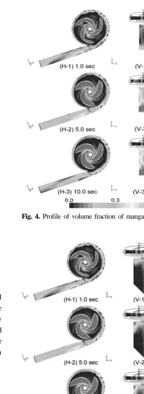
For the boundary condition, we have used constant velocity at the inlet and outlet boundary condition at the outlet. Figs. 4 and 5 show the volume fraction of manganese nodules calculated from the simulation analysis. Each figure shows X-Y horizontal sections at the impeller and X-Z vertical sections at the whole pump. From the observation of solid volume fraction, it is shown that pumping efficiency is decreased when
solid particles accumulate densely and impede favorable flow stream at the inlet or outlet areas of the pump including the impeller. From this, we can determine Fig. 2. H-Q performance curve of lift pump and analysis
condition for numerical analysis.
Fig. 3. Conformal and non-conformal grid system around the impeller.
Fig. 4. Profile of volume fraction of manganese in Model 1.
Fig. 5. Profile of volume fraction of manganese in Model 2.
which model is more efficient.
The volume fractions of manganese nodule at the X- Y sections (H-1), (H-2) and (H-3) shows that the solids are more concentrated at the opposite of impeller rotation blades which rotate clockwise. Solid particles occupy almost 60% of the area. The manganese nodules of high density get considerable acceleration by the impeller's rotation energy and come close to the impeller's rotation speed. These nodules accumulate at the curved area, and it explains the phenomena.
Model 1 in Fig. 4 shows that the accumulation reaches the highest point at the time of 5 sec and becomes to decrease at 10 sec after the rotation of impeller begins.
Model 2 in Fig. 5 shows almost the same aspects as in Model 1 in Fig. 4. X-Y sections in Fig. 4 and 5 indicate that the solid volume fraction becomes high at the impeller and outer part of the pump casing, because the manganese nodules with higher density receive more acceleration than water by the centrifugal force that the impeller rotation causes.
X-Z sections (V-1), (V-2) and (V-3) in Figs. 4 and 5 show the change of manganese volume fractions in Model 1 and 2 according to time. In the case of Model 1, the nodule accumulates in the connection part of pump edges and casing at 5 sec in Fig. 4. At 10 sec in Fig. 4, the accumulation is more severe than at 5 sec in Fig. 4, which is the connection area of the impeller and the main part of the pump. It was estimated that these phenomena especially will impede the manganese nodules into the impeller and exert a bad influence on the pump operation. On the other hand, it is observed that nodule accumulation occurs partly at the upper edges of the main body or at the impeller in Model 2 (X-Z sections) in Fig. 5. The accumulation was alleviated at the corner of the inlet where accumulation happened severely as in Model 1 and it is estimated that higher efficiency enhancement of the pump will be gained.
Manganese nodule flow and pressure trend at the inlet and outlet part
Fig. 6 shows the volume fraction of manganese nodules according to time at the inlet and outlet of the pump. Model 1 and 2 show similar tendency of the volume fraction, but it is estimated that the efficiency of Model 2 is better than that of Model 1 because
Model 2 has lower solid volume fraction at the inlet part compared with Model 1. As was clarified in the above flow tendency analysis, Model 1 shows wider accumulation area of the pump. But, Model 2 shows better results without the accumulation.
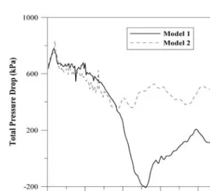
Fig. 7 illustrates the total pressure drop between inlet and outlet that can be used as a performance index of the pump. In the early stage, the difference is large because dynamic pressure at the inlet is relatively higher than at its outlet. In Model 1, the total pressure difference becomes negative at 4.5 sec, which is estimated because the dynamic pressure distribution is normal but the static pressure distribution is abnormally low in spite of the fact that the manganese nodules do not flow backward at the outlet of Model 1 as in the Fig. 8. As was discussed in Figs. 4 and 5, the manganese nodules accumulate at the pump impeller and inlet area of the pump, which exert bad influences on the pump in Model 1. In Model 1, the efficient pumping is impossible because the total pressure difference is remarkably low even after the pressure recovers positively after 6 sec. On the contrary, in Model 2, the pressure difference stabilizes and approaches approximately 550,000 Pa that corresponds to the total head of the pump of 55 meters at 5 seconds point. From the analysis, it is shown that Model 2 performs stable lifting and Model 1 shows inefficiency in its operation.
Fig. 8 shows the mass flow rate at the inlet and outlet.
In Model 1 and 2, no manganese nodules could discharge Fig. 6. Volume fractions of manganese at inlet and outlet.
until 1.2 sec and are stabilized to show the discharge range of 42 - 52 kg/sec. For the precise simulation, additional study on the boundary condition is needed from the actual experiments.
Conclusions
The lifting pump is essential for the lifting system of deep-sea manganese nodules. In this study, three- dimensional CFD studies with program FLUENT were performed to understand the solid-liquid two phase
flow phenomena that happen in the hydraulic pumping system, which could be resulted in the optimum design of the lifting pump. The results are summarized as follows:
1. Eulerian multi-phase model was used to describe a solid-liquid two-phase flow of a lifting pump. This model is designed to be accurate for the case of high volume fraction of solids. The boundary conditions at the inlet and outlet parts were determined using the performance chart of the pump. The non-conformal mesh was applied to the areas of pump impeller and the casing where the turbulent flow was expected.
2. Flow efficiency of the pump was investigated through the flow analysis of solid volume fraction. The particles are accumulated at the opposite area of the rotation blades of the impeller and the volume fraction was calculated as high at the impeller and the outer part of the pump casing, because higher acceleration acts on solids as compared with water.
3. Model 1 where the inlet part expands rapidly shows severe solid accumulation at the inlet edges, the casing and the connection pipes. On the contrary, Model 2 where the inlet expands gently showed only small accumulation at the upper edge and impeller, which indicates the better efficiency.
4. The total pressure difference between the inlet and outlet can be used as the efficiency index for a pump.
It was observed that the total pressure difference showed negative at 4.5 sec and stayed low pressure till the last stage in Model 1. On the other hand, it was shown that the result of Model 2 was similar with the performance of the pump developed previously and also that Model 2 can acquire efficient lifting because the high total pressure can be maintained.
Acknowledgements
The authors express appreciation to the Ministry of Maritime Affairs and Fisheries (MOMAF) of Korea for their full support in this study.
Refernces
Chung, J.S., 1994, “Advanced in Deep-Ocean Mining Systems Research” Proceedings of 4th International Fig. 7. Total pressure difference of inlet and outlet of
Model 1 and Model 2.
Fig. 8. Mass flow rate of Model 1 and Model 2 at the outlet.
Offshore and Polar Engineering Conference, pp. 18-31.
Chiesa, M., Mathiesen, V., Melheim, J.A., and Halvorsen, B., 2005, “Numerical Simulation of Particulate Flow by the Eulerian-Lagrangian and the Eulerian-Eulerian Approach with the Application to a Fluidized Bed,” Computer &
Chemical Engineering, Vol. 29, pp. 291-304.
Drew, D.A., and Lahey, R.T., 1993, In Particulate Two- Phase Flow, Butterworth-Heinemann, Boston.
Fluent Inc., 2001, Fluent 6.0 User’s Guide.
Gerber, A.G., and Kermani, M.J., 2004, “A Pressure Based Eulerian-Eulerian Multi-phase Model for Non-equilibrium Condensation in Transonic Steam Flow,” International Journal of Heat and Mass Transfer, Vol. 27, pp. 2217- 2231.
Ishii, M., 1975, Thermo-fluid dynamic theory of two-phase flow, Eyrolles, Paris.
Launder, B.E., and Spalding, D.B., 1974, “The numerical computation of turbulent flows,” Comp. Meth. In Appl.
Mech. And Eng., Vol. 3, pp. 269-289.
Pantankar, N.A., and Joseph, D.D., 2001, “Modeling and Numerical Simulation of Particulate Flow by the Eulerian- Lagrangian Approach,” International Journal of Multiphase Flow, Vol. 27, Issue 10, pp. 1659-1684.
Patankar, S.V., 2002, “Computational Modeling of Flow and Heat Transfer in Industrial Applications,” International Journal of Heat and Fluid Flow, Vol. 23, pp. 222-231.
Yoon, C.H., Kwon, K.S., Kwon, S.K., Lee, D.K., Park Y.C., and Kwon, O.K., 2001, “A Study on Efficiency of an Aif-lift Pump for Pumping Solid Particles,” Journal of The Korean Institute of Mineral and Energy Resources Engineers, Vol. 38, No. 5, pp. 341-351. (in Korean) Yoon, C.H., Park Y.C., Lee, D.K., Kwon, K.S., and Kwon,
S.K., 2003, “Hydraulic Pumping Test System of KIGAM for Deep-Sea Manganese nodules,” Proceedings of 33rd Underwater Mining Institute, pp. 131-135.
이 동 길 성 원 모
현재 한양대학교 공과대학 지구시스템공학 박사과정 현재 한국지질자원연구원 지반안전연구부 연구원 (本 學會誌 第 卷 第43 2号參照)
현재 한양대학교 공과대학 지구시스템공학 교수 (本 學會誌 第 卷 第43 2号參照)