SS400-STS304 이재용접부의 외력작용시 용접잔류응력 특성
방희선
*
․방한서*
․김유철**
․주성민***
․좌순원****
․노찬승*****, †
* 조선대학교 공과대학 선박해양공학과
** 일본 오사카대학교 접합과학연구소
*** 포항산업과학연구원 용접센터
**** 경남도립거창대학 조선공학과
*****
조선이공대학 선박해양·기계공학과
Influence of Welding Residual Stress on the Mechanical Behavior of Externally Loaded Dissimilar SS400-STS304 Steel Weldment
Hee-Seon Bang*, Han-Sur Bang*, You-Chul Kim**, Sung Min Joo***, Soon-Won Joa**** and Chan-Seoung Ro*****
,
†*Dept. of Naval Architecture & Ocean Engineering, Chosun University, Gwangju 501-759, Korea
**Joining & Welding Research Institute, Osaka University, Osaka 567-0047, Japan
***Welding Center, Research Institue of Industrial Science and Technology, Pohang 790-330, Korea
****Dept. of Naval Architecture Engineering, Gyeongnam Provincial Geochang College, Geochang 670-804, Korea
*****Dept. of Naval Architecture & Mechanics Engineering, Chosun College of Science and Technology, Gwangju 501-744, Korea
†Corresponding author : csro@chosun-c.ac.kr
(Received November 10, 2008 ; Revised January 14, 2009 ; Accepted September 24, 2009)
Abstract
Thermal and mechanical characteristics in dissimilar SS400-STS304 steel weldment have been investigated by 3D thermal elastic-plastic analysis. Moreover, the influence of welding residual stresses on the mechanical behaviour of this welded joint, by applying superimposed external load (tension load) was determined. The residual stresses obtained by numerical simulation were compared with the experimentally measured results. The FE results were in good agreement with the measured values. The mechanical test (hardness, tensile test) and metallurgical analysis was carried out to ensure the weld integrity. Hence, possibility of applying SS400-STS304 dissimilar steels in industries has been established.
Key Words : Dissimilar SS400-STS304 steel weldment, 3D thermal elastic-plastic analysis, Welding residual stress, External load
1. INTRODUCTION
Residual stresses and distortions are two of the major concerns in welded structures. Welding residual stresses not only cause distortion but also significantly affect the service characteristics
of welded structures. The residual stresses in weld region are normally tensile and close to the material yield stress due to the shrinkage of the weld on cooling. The combination of high tensile residual stresses in weld region and tensile loads applied can promote brittle fracture that increases the susceptibility of weld to fatigue
연 구 논 문
damage 1,2) . Notably, welding of dissimilar materials produces different residual stresses because of the differences in the coefficient of thermal expansion and heat conductivity of the two welded materials, compared to similar materials;
knowing of residual stress level allows avoid the failure of welded joints.
In the present study, thermal conduction and thermal elasto-plastic numerical analysis was performed using a developed program 3) to clarify the welding residual stress and plastic strain characteristics of dissimilar SS400-STS304 steel weldment. In order to verify the numerical simulation results, welding residual stress results obtained by numerical analysis on dissimilar SS400-STS304 steel weldment were compared with the experimentally measured residual stresses results. The strength of this dissimilar welded joint was evaluated by mechanical test (hardness, tensile test) and metallurgical analysis. Moreover, longitudinal residual stresses, which are most harmful to the integrity of the structure among the residual stress components, have been investigated by applying superimposed external load (tension load).
2. RESEARCH METHODS 2.1 Numerical analysis
2.1.1 Theoretical background for heat transfer and thermal elasto-plastic FE analysis When welding is carried out over a con- siderable length, heat flow attains a quasi stationary state that can be treated as a steady state flow problem for a moving coordinate in the whole welded area, except in areas near the start and end of welding. Therefore, in the present work the heat conduction and thermal elastic-plastic analysis is carried out in areas remote from end effects, assuming heat flow is in a quasi stationary state. For the formulation of finite elements of the thermal-elastic-plastic computer program, the governing equation of a non-stationary heat conduction problem when
the material is isotropic and continuous is given by equation (1) as
t T Q
c T = ∇ =
∂
∂ λ 2
ρ (1)
where, T is temperature (℃), ρ is density (g-cm -3 ), Q is rate of temperature change due to heat generation per volume (cal-cm -3 .sec -1 ), t is time (sec), λ is thermal conductivity of isotropic material (cal-cm -1 .sec -1 .℃ -1 ) and c is specific heat (cal-g -1 .℃ -1 ) 4) .
The temperature dependent material properties such as yield strength and elastic modulus are considered, through the elastic and plastic regions, for the welding residual stress and strain program. In the elasto-plastic problem, the total increment of strain is the summation of increment in elastic strains, plastic strains and thermal strains and is given by equation (2) as
{ d ε } = { d ε e } + { d ε p } + { d ε T } (2) where, {dε e } increment of elastic strain, {dε p } increment of plastic strain and {dε T } increment of thermal expansion strain.
Data transferring between commercial FE package and developed PATRAN Command Language (PCL) program can be compiled directly from the PATRAN desktop which is used for making a basic interface between the developed in-house solver and commercial package ANSYS.
2.1.2 Method of numerical analysis
The principal dimension of the model for
numerical analysis is shown in Fig. 1(a). It is
assumed that a 400×400×15 mm size specimen
model is sufficient for a good simulation of a real
process. The materials properties of mild steel
SS400 and stainless steel STS304, as per KS
(Korean Standards) were considered. The chemical
compositons of base metals and welding
condition for dissimilar steel are given in Table
1 and 2 respectively. SS400-STS304 steel weldment
with 15mm thickness is performed using five-
Welding direction
400mm(L) Y
X Z 15 mm( T)
40 0m m (B )
(a) Configuration of welded specimen and coordinate
SS400 SS304
Y
X
(b) FE model and boundary condition for numerical analysis Fig. 1 Welded specimen details and boundary
condition for analysis
Material C Si Mn P S Ni Cr Mo
SS400 0.16 0.32 1.63 0.008 0.013 0.03 0.04 -
STS304 0.032 0.46 1.43 0.028 0.028 8.55 18.2 0.29
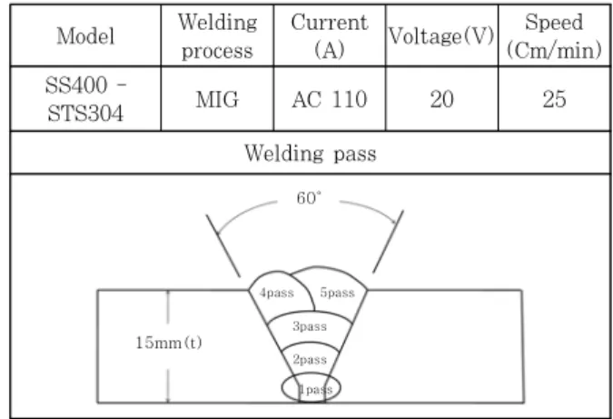
Table 2 Welding condition and process parameters Model Welding
process
Current
(A) Voltage(V) Speed (Cm/min) SS400 -
STS304 MIG AC 110 20 25
Welding pass
60°
15mm(t)
4pass 5pass 3pass 2pass 1pass
Table 1 Chemical compositions of SS400 and STS304 steels (wt.%)
12
10
8
6
4
2
0
24
20
16
12
8
4
0 200 400 600 800 1000
T(℃)
0.98 2.2 10.8 7.82
ρ
λ
α c
21.4
7.61
4.4 2.18 α·10
6: linear expansions coeff.
λ·10
3: thermal conductivity(cal/cm ·sec ·℃) c ·10 : specific heat(call/g ℃)
ρ·10
3: density(g/cm
3)σ
v(MPa)
1000
750
500
250
σ
YH(Base metal) σ
YW(Weldmetal and HAZ)
Weldmetal and HAZ
ν=0.3 Linear expansion coeff.
α=1.2·10
-5(l/℃)
E(GPa)
200
150
Young ’s modu lus
50
200 400 600 800
Temperature(℃)
Yield streng th
Poisson’s ratio
100
Fig. 2 Physical and mechanical properties of SS400 pass welding process. The groove angle is
selected as per the welding standards and similar groove dimension is considered for simulation also.
The MIG welding method is conducted with the STS 309 welding rod. Boundary condition for the elasto-plastic analysis was considered with actual restrained condition as shown in Fig. 1b. The mesh is made finer at the weld zone to get the accurate results. Physical and mechanical properties of mild steel (SS400) and STS304 is shown in Fig. 2 and 3 5) .
2.2 Experiment details
Specimen of 400×400×15 mm size was welded
with MIG welding process. Welding residual
stress is measured by sectioning techniques of
stress-relaxation method (non-destructive method)
using strain gauges near the weld region. The
checkpoints for welding residual stresses were
selected in accordance with the result of
12
10
8
6
4
2
0
Temperature(℃)
0 200 400 600 800 1000
24
20
16
12
8
4
0.11 3.4 3.9 7.86
c α
λ ρ
α·10
6: linear expansions coeff.
λ·10
3: thermal conductivity c ·10 : specific heat ρ·10
3: density
Temperature(℃)
σ(MPa) E(GPa)
1000
750
500
250
Yi el d st ren g th Yo ung ’s mod u lu s
200
150
50 100 Linear expansion coeff.
α=1.7·10
-5E
σ
UBσ
UHσ
YBσ
YHFig. 3 Physical and mechanical properties of STS 304
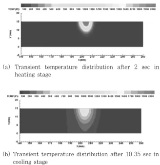
(a) Transient temperature distribution after 2 sec in heating stage
(b) Transient temperature distribution after 10.35 sec in cooling stage
Fig. 4 Temperature field after the 5th pass welding of the dissimilar steel weldment
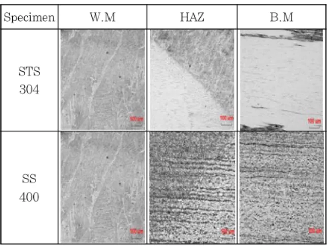
numerical analysis and measurement is carried out at the centre (z = 200mm) along the width direction of weldment. Mechanical tests such as tensile test, hardness test and micro-structure analysis were carried out in order to establish the mechanical phenomenon of welded joint experimentally. Tensile test is carried out under a perpendicular load to the weld axis with a crosshead speed of 5mm/min. Vickers hardness is measured near weld metal with the load 10kgf. The hardness was measured at points, 2mm away from the upper part. An image analysis technique is utilized to determine the porosity fraction and the microstructure is observed by scanning electron microscopy (SEM).
3. RESULTS AND CONSIDERATIONS 3.1 Numerical Analysis results
3.1.1 Thermal characteristic of dissimilar steel weldment
By using the non-stationary thermal conduction program, the results obtained from the thermal characteristics analysis in welded joint were compared. The characteristics of thermal dis- tribution, that cause residual stresses, have been investigated.
Fig. 4 illustrates the temperature field after
heating the 5th weld pass in the welded joint.
The heat dissipates into SS400 more rapidly
than STS304, which means that the thermal
conduction of SS400 is higher than that of
STS304. Fig. 5 shows the temperature variation
of elements, at 6mm depth from the upper
surface of plates, along the direction of width of
welded joint from sec 2 sec to 36 sec. The
maximum heating and minimum cooling temperature
appears in dissimilar steel weldment at 2
2.00Sec.
5.18Sec.
10.66Sec.
35.85Sec.
2500
2000
1500
1000
500
0
0 100 200 300 400
X(mm)
T e mper ature(℃)
Fig. 5 Temperature variation of the dissimilar steel weldment
seconds and 35.85 seconds respectively, after the commencement of welding From the analysis results, it is found that the temperature changes abruptly in the vicinity of weld and gently as being away from the welds. Besides, temperature gradient appeared sluggishly with respect to time. When comparing SS400 and STS304 during cooling, it is showed that SS400 has the gently- slopping temperature gradient and the thermal conduction progresses faster in SS400.
3.1.2 Mechanical characteristic of dissimilar steel weldment
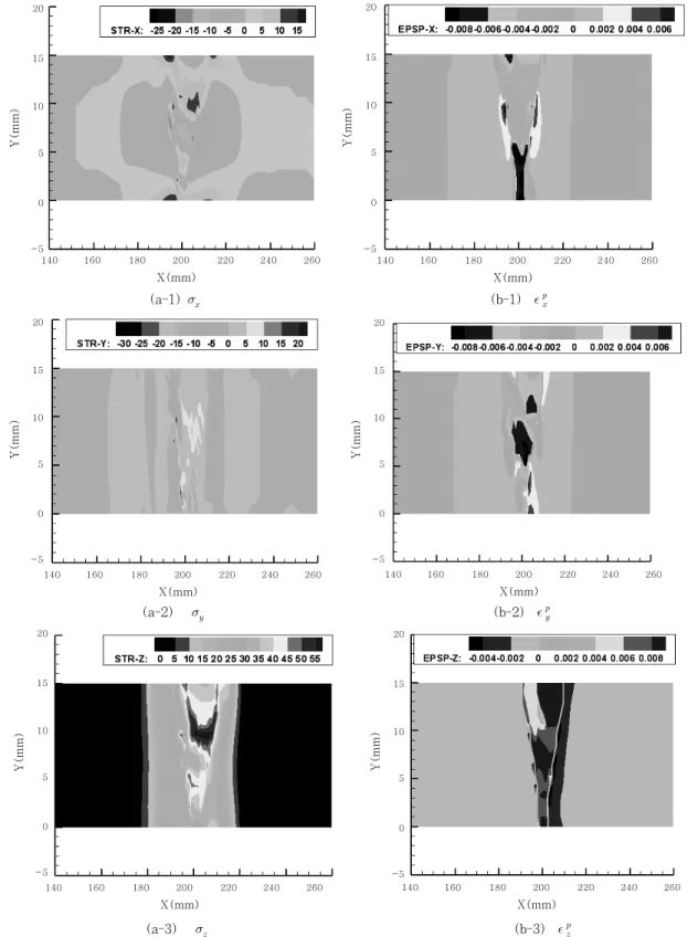
The developed thermal elasto-plastic program simulates the mechanical phenomenon of welding residual stress and plastic-strain in dissimilar joint weldments. Fig. 6 illustrates the welding residual stress and plastic strain, caused along the direction of thickness. When observing the characteristic of welding residual stress of each component, if weld metal is cooled down below 700℃, it recovers its mechanical rigidity and stress, which is generated in weld metal as its contraction is restricted by base metal in vicinity of weld during cooling 6) . In Fig. 6, residual stress in the longitudinal direction indicates the tension along the longitudinal direction σ
zof weld metal and heat affected zone, and reaches maximum in HAZ, and changes to compression in base metal in vicinity of HAZ. Especially, residual stresses σ
yin the thickness direction are higher and the minimum value appears on residual stress σ
xin the transverse direction.
While comparing the magnitude of stress values, dissimilar steel weldment shows stresses in the order σ
z> σ
y≥ σ
x. This indicates that weldment experiences the different amount of mechanical restraint. When comparing residual stress for base metal, residual stress σ
xin the transverse direction is higher in STS304 and residual stress σ
yin the thickness direction is higher in SS400 respectively. This implies that the mechanical restraint conditions are different in both materials after welding. The plastic strain
p