Journal of the Korean Society for Composite Materials, 25(4), 98-104(2012), pISSN: 1598-6934 DOI: http://dx.doi.org/10.7234/kscm.2012.25.4.98
’12 춘계학술대회 우수 논문
요추유합술에서 응력방패 현상 감소를 위한 케이지의 유한요소해석 : CFRP 케이지와 티타늄 케이지 비교 연구
강경탁
*, 전흥재
*+, 김호중
**, 염진섭
**, 박경미
*, 황인한
*, 이광일
***Finite Element Analysis of Instrumented Posterior Lumbar Interbody Fusion Cages for Reducing Stress Shielding Effects: Comparison of the CFRP cage and Titanium cage
Kyung-Tak Kang
*, Heoung-Jae Chun
*+, Ho-Joong Kim
**, Jin-S. Yeom
**, Kyoung-Mi Park
*, In-Han Hwang
*, and Kwang-Ill Lee
***ABSTRACT
In recent years, degenerative spinal instability has been effectively treated with a cage. However, little attention is focused on the stiffness of the cage. Recent advances in the medical implant industry have resulted in the use of medical carbon fiber reinforced polymer (CFRP) cages. The biomechanical advantages of using different cage material in terms of stability and stresses in bone graft are not fully understood. A previously validated three-dimensional, nonlinear finite element model of an intact L2-L5 segment was modified to simulate posterior interbody fusion cages made of CFRP and titanium at the L4-L5 disc with pedicle screw, to investigate the effect of cage stiffness on the biomechanics of the fused segment in the lumbar region. From the results, it could be found that the use of a CFRP cage would not only reduce stress shielding, but it might also have led to increased bony fusion.
초 록
본 논문에서는 척추체 간 유합용 케이지의 응력방패현상을 감소시키기 위하여 강성 차이에 대한 연구를 수행하였다. 최근 의료 임플란트 분야에서는 탄소섬유강화 폴리머를 이용하여 좋은 결과를 보여 왔다. 그러나 생체 역학적으로 이 재료에 대하 여 요추체의 안정성과 골 이식재가 받는 응력에 관련한 연구는 없었다. 따라서 이전에 유효화한 요추체 (L2-L5) 비선형 유한 요소 모델을 이용하여 L4-L5 분절의 케이지의 강성 차이에 따른 효과를 알아보기 위하여 탄소섬유강화 폴리머와 티타늄 케 이지를 이용한 후방 요추체 유합 모델을 만들었다. 자가골 보다 강성이 작은 탄소 섬유강화폴리머 케이지는 인접 분절의 하 종판에 응력이 적게 걸리며, 골 이식재에 응력은 증가시켰다. 위의 결과로 탄소섬유강화 폴리머 케이지는 응력 방패 현상을 감소시킬 수 있을 뿐만 아니라 골 유합률을 증가시킬 수 있다.
Key Words : 유한요소해석(finite element analysis), 응력방패(stress shielding), 케이지(cage), 탄소섬유강화 폴리머(carbon fiber reinforced polymer)
2012년 춘계학술대회 우수논문(무심사)
* School of Mechanical Engineering, Yonsei University
*+ School of Mechanical Engineering, Yonsei University, Corresponding author(E-mail:[email protected])
** Spine Center and Department of Orthopaedic Surgery, Seoul National University College of Medicine and Seoul National University Bundang Hospital
*** Brain Korea 21 Project for Medical Science, Yonsei University
1. Introduction
Intervertebral disc degeneration or damage resulting from acute and chronic spinal injury induces spinal structure instability. Spinal structure instability can be resolved by spinal fusion, a surgical treatment where the defective disc column has a spinal cage implant inserted to provoke bony growth and thus, form the bridging vertebrae. Subsequently, the fused configuration of the adjacent vertebrae successfully restores the ordinary spinal column height and stabilizes the structure of the functional spine unit. The goals of the posterior lumbar interbody fusion procedure using cages with pedicle screw and graft bone are to stabilize the motion segment and facilitate the fusion process. These cages were initially manufactured using either medical grade stainless steel or titanium alloys. Recent advances in the medical implant industry have resulted in the use of medical grade carbon fiber reinforced polymer (CFRP). Because of their excellent properties, polymer composites have been widely used in many fields, including the automobile and medical device industries [1-2]. When composites are used in the medical field, appropriate material selection should be carefully undertaken. For that reason, noncorrosive and bio-compatible metals, such as titanium, have been used in many medical tools and implants. Conventional metal cases inevitably cause a stress-shielding effect because of their excessively high modulus relative to living bone. To investigate the influence of material on the stress shielding effect, stress response and bony growth progress were observed by in vivo and in vitro simulations, respectively. The cortical bone interbody cage possessed the same stress shielding potential as titanium and stainless steel implants of identical geometry, even though the Young’s modulus of the metal was larger than that of the cortical material in vitro research by Martijn et al [3-4]. The results demonstrated that the softer poly-l-lactide (PLLA) cage accelerated the rate of lumbar fusion compared with the titanium cage in a Dutch milk goat spine. A claimed advantage and the driving force in support of using CFRP is that its Young’s modulus (“E” = 9 GPa) is much closer to that of cortical bone (“E” = 12 GPa), as compared to titanium (“E” = 110 GPa). Investigations on stress analysis of various developed spinal cages are customary in spinal works, but the key factors which reduce the stress shielding effect and biomechanical advantages of this difference are still not well understood. In formulating the present study, our hypothesis is that a CFRP cage with pedicle screw provides stability similar to a titanium cage with pedicle screw but allows larger loads
to go through the bone graft and reduces stress on the bony endplates. The purpose of this study was to evaluate this hypothesis by comparing the biomechanical performance of a posterior lumbar interbody fusion cage made of CFRP with the commonly used titanium cage using the finite element approach.
2. Materials and Methods
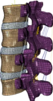
2.1 FE model of the intact lumbar spine (L2-L5) We developed a three-dimensional (3D) nonlinear FE model of the lumbar spine that consisted of four lumbar vertebrae, three intervertebral discs, and the associated spinal ligaments. Geometrical details of the human lumbar spine (L2-L5) were obtained from high-resolution Computed Tomography (CT) images of a 46-year-old man with no spinal deformities. Digital CT data were imported into the Mimics software program (Materialise Inc., Leuven, Belgium), which was used to generate the 3D geometrical surface of the lumbar spine. Initial Graphic Exchange System (IGES) files exported from the Mimics software were input into Unigraphics NX 3.0 (Siemens PLM Software, Torrance, CA) to form solid models for each vertebral segment. The solid model was then imported into Hypermesh 8.0 (Altair Engineering, Inc., Troy, MI) to generate FE meshes (Fig. 1).
The FE method was analyzed with ABAQUS version 6.6-1 (Hibbitt, Karlsson and Sorenson, Inc., Providence, RI).
Three-dimensional homogeneous and transversely isotropic solid elements were used to model the cortical and cancellous cores and the posterior bony parts of the vertebrae. We used tension-only truss elements to model the anterior longitudinal ligament, posterior longitudinal ligament, intertransverse ligament, ligamentum flavum, capsular ligament, interspinous ligament, and supraspinous ligament.
Fig. 1 Intact Model.
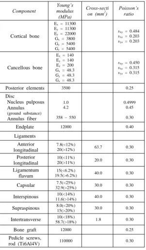
Table 1 Material properties in the present FE model Component Young’s
modulus (MPa)
Cross-secti
on (mm2) Poisson’s ratio
Cortical bone
Ex = 11300 Ey = 11300 Ez = 22000 Gx = 3800 Gy = 5400 Gz = 5400
υxy = 0.484 υxz = 0.203 υyz = 0.203
Cancellous bone
Ex = 140 Ey = 140 Ez = 200 Gx = 48.3 Gy = 48.3 Gz = 48.3
υxy = 0.450 υxz = 0.315 υyz = 0.315
Posterior elements 3500 0.25
Disc
Nucleus pulposus Annulus (ground substance) Annulus fiber
1.0 4.2 358 – 550
0.4999 0.45 0.30
Endplate 12000 0.40
Ligaments Anterior longitudinal
7.8(<12%)
20(>12%) 63.7 0.30
Posterior longitudinal
10(<11%)
20(>11%) 20.0 0.30
Ligamentum flavum
15(<6.2%)
19.5(>6.2%) 40.0 0.30
Capsular 7.5(<25%)
32.9(>25%) 30.0 0.30
Interspinous 10(<14%)
11.6(>14%) 40.0 0.30
Supraspinous 8.0(<20%)
15(>20%) 30.0 0.30
Intertransverse 10(<18%)
58.7(>18%) 1.8 0.30
Bone graft 12000 0.25
Pedicle screws,
rod (Ti6Al4V) 110000 0.30
2.2 Material properties
Material properties were selected from the literature (Table 1) [5-8]. The cortical and cancellous regions of the vertebrae were modeled independently. It was difficult to differentiate between the cortical and trabecular bone in the posterior region; therefore, the posterior elements were all assigned a single set of material properties. The annulus fibrosus was modeled as a composite of solid matrix with embedded fibers (using the REBAR parameter) in concentric rings surrounding a nucleus pulposus, which was considered to be an incompressible inviscid fluid. Element members with a hybrid formulation (C3D8H) combined with a low elastic modulus and large Poisson ratio definitions were applied to simulate the nucleus pulposus. Eight-node brick elements were employed to model the matrix of the ground substance. Each of four concentric rings of ground substance
contained two evenly spaced layers of annulus fibers oriented at ±30° to horizontal.
The reinforcement-structure annulus fibers were represented by truss elements with modified tension-only elasticity. In the radial direction, four double-cross-linked fiber layers were defined, and these fibers were bound by the annulus ground substance and both endplates. In addition, these fibers had proportionally decreased elastic strength from the outermost (550 MPa) to the innermost (358 MPa) layers [9,10]. Naturally varying ligament stiffness was simulated through a “hypoelastic”
material designation, in which stiffness was initially low at low strains but became increasingly stiff at higher strains (Table 1).
Three-dimensional truss elements were used to simulate ligaments, which were active only in tension.
2.3 Model simulation
To make the posterior lumbar interbody fusion (PLIF) model, subtotal laminectomy and medial facetectomy of the intact model were performed at the L4-L5 level, including removal of the supraspinous, interspinous, and flavum ligaments. The cranial margin of laminectomy was the point corresponding to the cranial end of the ligament flavum, and the lateral margin was the medial one-third of the facet joints.
A posterior pedicle screw fixation (Stryker, South Allendale, NJ, USA) was added to the L4-L5 PLIF. All screws had sharp threads to prevent relative motion at the bone-screw interface and were inserted into the anterior one-third of the vertebral body through the pedicles. The pedicle screws did not violate the medial wall of the pedicle or the endplates.
Except for the screw tip, the remaining surface of the screw was fixed to the bone without allowing relative motion. A
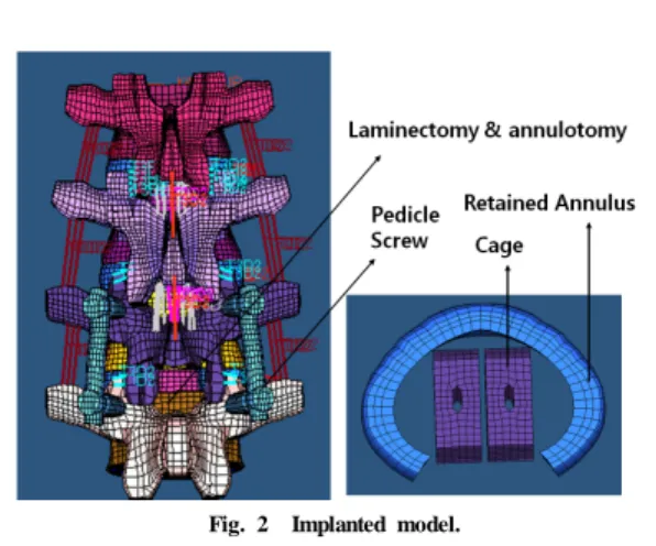
“tie” contact condition was used to enable the screw threads and vertebrae to be permanently bonded together by full constraint. The diameters of all pedicle screws were assumed to be 5.0 mm, with a mean outer diameter of 6.5 mm (including thread height). The lengths of the screws in L4 and L5 were 40 mm (Fig. 2). A posterior approach for a monobloc, box-shaped cage, based on the CFRP cage (Depuy Spine, MA, USA), was modeled. The CFRP cage was made of short fiber and its material properties were assumed to be homogeneous isotropic (Fig. 2).
The cage size was chosen according to the space between the vertebrae, as proposed by the manufacturer, to restore lordosis and disc height. The original convex shape of the implant was not included in the model as the fit between the curved endplates and a flat implant would represent the severe loading case of edge contact and was realistic for quite
Fig. 2 Implanted model.
a number of existing cages. To fit the cage, the posterior longitudinal ligament, the nucleus pulposus and the necessary amounts of fiber and annular elements were removed. The bone-cage interface was modeled by surface-to-surface contact elements to simulate early postoperative stage after implantation of spinal cage. These contact elements are able to transmit compression forces but not tension. Most cages have small teeth on the contact surfaces, that are supposed to prevent movement of the cage therefore, a higher friction coefficient of 0.8 was defined between the cage and the adjacent vertebrae [10]. CFRP (“E” = 12 GPa) and titanium (“E” = 110 GPa) material properties were assigned to the cage model to simulate cages of two levels of stiffness.
2.4 Boundary and loading conditions
This FE investigation included two types of loading conditions corresponding to loads used in the experimental part of the study for model validation and model predictions for clinically relevant loading scenarios [11]. Validation included loading the model with 10 Nm of moments. The nodes of the inferior surfaces of the inferior-most vertebral body were completely fixed in all directions. To validate the model, the same loading conditions used in the Yamamoto et al’s study were applied [11]. Nodes on top of the L2 vertebra were defined as coupling nodes. A reference node was created and connected to all coupling nodes. A coupling element was, thus, created to distribute moments on the reference node. Therefore, 10 Nm flexion, 10 Nm extension, 10 Nm torsion, and 10 Nm lateral bending moment under the 150 N preload were imposed on the L2 vertebral body, respectively. To reach 10 Nm moment, the five load steps were applied to the intact model. The second type of loading
Fig. 3 Intact FE model with the tract of follower compressive load.
condition was the load control protocol. The follower load technique was used to simulate the vector sum of trunk muscle co-activation by a single internal force vector that acted tangentially to the curvature of the spine, passing through each segmental center of rotation [12]. This
“follower” path, tangential to the curvature of the spine, mimicked physiologic compressive loads on the lumbar spine observed in vivo. The 400 N compressive follower load was simulated at each motion segment in the model by a pair of two-node thermo-isotropic truss elements. The trusses were attached bilaterally to the cortical shell of the vertebrae at each motion segment. Each truss spanned the disc space passing through the instantaneous center of rotation at each motion segment [13,14]. This load control protocol involved the application of 7.5 Nm flexion, extension, torsion, and lateral bending pure moments and 400 N anterior shear force to four lumbar models on the L2 vertebral body under a 400 N follower load (Fig. 3).
3. Results
The intact L2-L5 model was validated in our laboratory, as reported in our prior publications [15-17]. The stress of the pedicle screw was found to be largest in lateral bending loading of the CFRP cage model (Fig. 4). The smallest stress of the pedicle screw occurred in extension of the titanium cage model (Fig. 4). The mean stress of the screw increased to -1% and -8% in the CFRP cage compared to that in the titanium cage model.
The stresses on the screw were similar in both types of cage materials under all loading conditions with the pedicle screw.
Fig. 5 is a comparison of the relative motion for the intact, CFRP cage with pedicle screw and titanium cage with
Fig. 4 Comparison of peak von Mises stresses on pedicle screw for a 400 N compression and a 7.5 Nm moment for spine with CFRP cage and pedicle screw, and spine with titanium cage and pedicle screw.
Fig. 5 Comparison of range of motion across L4-L5 for a 400 N compression and a 7.5 Nm moment for intact spine, spine with CFRP cage and pedicle screw, and spine with titanium cage and pedicle screw.
pedicle screw models in response to a 400 N axial compression and a 7.5 Nm bending moment. The relative range of motion across L4-L5 functional spinal units decreased for all loading cases with the cage and pedicle screw. The range of motion across the L4-L5 functional spinal units was less than 0.5° for all loading cases with the spinal pedicle screw and was similar for both types of cage materials.
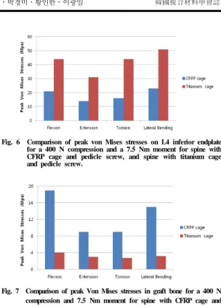
Fig. 6 is a comparison of the peak centroidal Von Mises stresses seen on the endplate for a 400 N compression and a 7.5 Nm bending moment in various loading conditions for spines with CFRP and titanium cages. The stresses in the endplate increased by at least 2.75 fold when a titanium cage was used in place of a CFRP cage. A maximum stress of 51 MPa was seen by the endplate in lateral bending for the spine with titanium cage and pedicle screw, as compared to 23 MPa for the CFRP cage and pedicle screw case.
Fig. 7 is a comparison of the peak centroidal Von Mises stresses seen by the bone graft for a 400 N compression and a 7.5 Nm bending moment in various loading conditions for spines with CFRP and titanium cages along with pedicle screw. The stresses in the bone graft increased 3 fold in
Fig. 6 Comparison of peak von Mises stresses on L4 inferior endplate for a 400 N compression and a 7.5 Nm moment for spine with CFRP cage and pedicle screw, and spine with titanium cage and pedicle screw.
Fig. 7 Comparison of peak Von Mises stresses in graft bone for a 400 N compression and 7.5 Nm moment for spine with CFRP cage and pedicle screw and spine with titanium cage and pedicle screw.
extension, 3.75 fold in torsion, 6.25 fold in lateral bending and 6.37 fold in flexion with a CFRP cage as compared to the regular titanium cage.
4. Discussion & Conclusions
A three-dimensional nonlinear finite element model of the lumbar spine was established to simulate the instrumented PLIF with cage. Such an investigation is not feasible in a cadaver model due to the inability to estimate stresses in various spinal structures. The results from the finite element study indicate that the stress magnitude in the endplate region was less for the CFRP cage as compared to the titanium cage. The smaller stresses in the CFRP cage case might result in lesser subsidence of the cages into the endplate and the adjoining cancellous bone over time. As the graft is stiffer (“E” = 12 GPa) than the CFRP cage (“E” = 9 GPa), the graft experiences higher stresses than the CFRP cage. As the titanium cage (“E” = 110 GPa) is stiffer than the bone graft (“E” = 12 GPa), it will stress shield the bone graft with likely implications on the rate of fusion in accordance with Wolff’s law. The CFRP cage acts
to keep the bone graft (higher stiffness compared to CFRP) in place and allows the graft to withstand higher loads/stresses.
The predicted motion data following cage placement with pedicle screw suggests that the stability provided by the cage is independent of the material properties, but the load transfer and related parameters are different. These parameters favor the use of CFRP cages over the titanium cages, as shown above. While titanium cages prevent adequate radiographic demonstration of fusion, CFRP being a radiolucent polymer allows a clear assessment of bony fusion. When used in conjunction with pedicle screw, cages of lesser stiffness, like CFRP, provide initial stability similar to titanium cages, might minimize the chances of subsidence, and would lead to higher stresses in the bone graft itself.
The use of a CFRP cage will not only reduce stress shielding, but it may also lead to increased bony fusion. This study provides a good and reasonable clinical guideline in appropriate stiffness application to the cage for interbody fusion, with respect to bone density of the patients.
Reference
1) Kang, K.T., Chun, H.J., Park, J.C., Na, W.J., Hong, H.T., and Hwang, I.H., “Design of a composite roll bar for the improvement of bus rollover,” Composites Part B:
Engineering, Vol. 43, No. 4, 2012, pp. 1705-1713.
2) Kim, S.H., and Chang, S.H., “Finite Element Analysis on bio-mechanical Behavior of Composite Bone Plate for Healing Femur Fracture considering Contact Conditions,”
Journal of the Korean Society for Composite Materials, Vol. 23, No. 1, 2010, pp. 1-7.
3) Palm, W.J., Rosenberg, W.S., and Keaveny, T.M., “Load transfer mechanisms in cylindrical interbody cage constructs,”
Spine, Vol. 29, No. 19, 2002, pp. 2101-2107.
4) Martijn, M., Smit, T.H., Sungihara, S., Burger, E., and Wuisman, P., “The effect of cage stiffness on the rate of lumbar interbody fusion: an in vivo model using poly(L-lactic acid) and titanium cages,” Spine, Vol. 27, No. 7, 2002, pp. 682–688.
5) Shirazi-Adl, S.A., Shrivastava, S.C., and Ahmed, A.M.,
“Stress analysis of the lumbar disc-body unit in compression.
A three-dimensional nonlinear finite element study,” Spine, Vol. 9, No. 2, 1984, pp. 120-134.
6) Pintar, F.A., Yoganandan, N., Myers, T., Elhagediab, A., and Sances, A., “Biomechanical properties of human lumbar
spine ligaments,” Journal of biomechanics, Vol. 25, No.
11, 1992, pp. 1351-1356.
7) Goel, V.K., Kim, Y.E., Lim, T.H., and Weinstein, J.N.,
“An analytical investigation of the mechanics of spinal instrumentation,” Spine, Vol. 13, No. 9, 1988, pp. 1003-1011.
8) Wu, H.C., and Yao, R.F., “Mechanical behavior of the human annulus fibrosus,” Journal of Biomechanics, Vol.
9, No. 1, 1976, pp. 1-7.
9) Shirazi-Adl, A., Ahmed, A.M., and Shrivastava, S.C.,
“Mechanical response of a lumbar motion segment in axial torque alone and combined with compression,”
Spine (Phila Pa 1976), Vol. 11, No. 9, 1986, pp. 914-927.
10) Polikeit, A., Ferguson, S.J., Nolte, L.P., and Orr, T.E.,
“Factors influencing stresses in the lumbar spine after the insertion of intervertebral cages: finite element analysis,”
Eur Spine J, Vol. 11, No. 6, 2003, pp. 413-420.
11) Yamamoto, I., Panjabi, M.M., Crisco, T., and Oxland, T.,
“Three-dimensional movements of the whole lumbar spine and lumbosacral joint,” Spine, Vol. 14, No. 11, 1989, pp.
1256-1260.
12) Patwardhan, A.G., Havey, R.M., Meade, K.P., Lee, B., and Dunlap, B., “A follower load increases the load-carrying capacity of the lumbar spine in compression,” Spine (Philadelphia, Pa 1976), Vol. 24, No. 10, 1999, pp.
1003-1009.
13) Bresnahan, L., Ogden, A.T., Natarajan, R.N., and Fessler, R.G., “A biomechanical evaluation of graded posterior element removal for treatment of lumbar stenosis:
comparison of a minimally invasive approach with two standard laminectomy techniques,” Spine (Philadelphia, Pa 1976), Vol. 34, No. 1, 2009, pp. 17-23.
14) Renner, S.M., Natarajan, R.N., Patwardhan, A.G., Havey, R.M., Voronov, L.I., Guo, B.Y., Andersson, G.B.J., and An, H.S., “Novel model to analyze the effect of a large compressive follower pre-load on range of motions in a lumbar spine,” Journal of Biomechanics, Vol. 40, No. 6, 2007, pp. 1326-1332.
15) Kim, H.J., Chun, H.J., Kang, K.T., Lee, H.M., Kim, H.S., Moon, E.S., Park, J.O., Hwang, B.H., Son, J.H., and Moon, S.H., “A validated finite element analysis of nerve root stress in degenerative lumbar scoliosis,” Medical &
Biological Engineering & Computing, Vol. 47, No. 6, 2009, pp. 599-605.
16) Kim, H.J., Chun, H.J., Moon, S.H., Kang, K.T., Kim, H.S., Park, J.O., Moon, E.S., Sohn, J.S., and Lee, H.M.,
“Analysis of biomechanical changes after removal of instrumentation in lumbar arthrodesis by finite element
analysis,” Medical and Biological Engineering and Computing, Vol. 48, No. 7, 2010, pp. 703-709
17) Kim, H.J., Chun, H.J., Moon, S.H., Kang, K.T., Kim, H.S., Park, J.O., Moon, E.S., Kim, B.R., Sohn, J.S., Ko,
Y.N., Jang, J.W., and Lee, H.M., “The biomechanical effect of pedicle screws' insertion angle and position on the superior adjacent segment in one segment lumbar fusion,” Spine, [Epub ahead of print]