*Corresponding Author : Kwang-Wook Youm(Hanyang cyber Univ.) Tel: +82-2-2290-0844 email: [email protected]
Received March 19, 2019 Revised April 9, 2019 Accepted June 7, 2019 Published June 30, 2019
A Study on the Integration of Motor - Transmission for Commercial
Electric Vehicle
Se-Hoon Oh1, Kwang-Wook Youm2*
1Department of Mechanical Engineering, ChungAng University
2Department of Mechanical and Automotive Engineering, Hanyang cyber University
상용전기자동차용 모터-변속기 일체화에 관한 연구
오세훈1, 염광욱2*
1중앙대학교 기계공학부, 2한양사이버대학교 기계자동차공학부
Abstract Owing to the present problems of air pollution and fossil fuel exhaustion, ongoing research has been actively focused on developing an electric actuator system that can utilize diverse energy sources without producing any exhaust gas. Since the motors of such electric vehicles generally rotate at a high speed, the initial acceleration capability required for an automobile is insufficient. In this study, the motor output was decelerated by the transmission; the initial acceleration of the vehicle was increased, and the motor size and weight were reduced. The driving motor and transmission, which each form isolated structures, were integrated to simplify the connector for input and output. By reducing the cooling system’s capacity, a vehicle was designed and manufactured that represents a structural change in effective technology.
요 약 전 세계적으로 자동차 산업에 있어서 현재 배기가스로 인한 대기오염과 화석연료의 에너지자원 고갈의 문제로 인해 배기가스 발생이 전혀 없고 다양한 방법으로 에너지원을 만들 수 있는 전기자동차의 전동 구동부 시스템에 대한 연구가 활발히 진행되고 있다. 이러한 전기 자동차는 차량의 중량에 따라 모터의 용량 및 사양이 달라지는데 그 중 상용 전기자동차에 사용하는 고용량의 전기모터는 크기가 크고 중량이 무거워서 제한된 배터리의 용량을 빨리 소비하여 주행 거리를 단축시킨다. 이러한 모터의 출력은 일반적으로 고속회전하기 때문에 자동차에 필요한 초기가속능력이 부족하다.
따라서 본 연구에서는 모터의 출력을 변속기를 통하여 감속시켜 차량의 초기가속능력을 높이고 모터의 크기와 중량을 상대적으로 줄였다. 그리고 각각의 분리된 구조를 이루고 있는 구동모터와 변속기를 일체화하여 입·출력을 위한 커넥터 의 간소화를 이루고 냉각시스템의 용량도 축소하여 차량을 설계하고 제작하거나 기존차량을 구조변경을 하는데 효과적 인 기술을 제시하였다. 또한 모터와 변속기를 일체화하기 위한 스플라인의 설계 및 해석을 통하여 적합성을 증명하였다.
Keywords : Commercial Electric Vehicle, Motor, Transmission, Spline, Integration
1. Introduction
Due to the EU-V, which is currently being addressed by air pollution due to exhaust emissions and the depletion of energy resources
of fossil fuels, and the EU-Ⅵ strengthened environmental regulations to be implemented in 2014 ~ 2015.[1] The development of eco-friendly vehicles such as electric cars, hybrid cars, and fuel cell vehicles with low consumption rates is
focused on.[2-5] Among them, research on an actuator system for electric vehicles is actively ongoing with the goal of utilizing energy sources through various methods without the generation of exhaust gas. These electric vehicles differ depending on the weight, motor capacity, and specifications. The high-capacity electric motor is large and heavy, so it consumes limited battery power quickly and reduces mileage. As this motor output generally rotates at a high speed, the initial acceleration does not meet the vehicle requirements. In this study, the initial acceleration was increased by decelerating the motor output, and the motor size and weight were decreased by reducing the battery consumption; an actuator system was developed for commercial electric vehicles that can increase mileage. The driving motor and transmission, which each form an isolated structure, were integrated to produce an effective technology for manufacturing new vehicles or changing the structure of existing vehicles.
2. Drive motor structure design
2.1 motor specification selection
Unit Specification
Power Instantaneous rating 200KW Continuos rating 100KW
Speed Base speed 3,500rpm
Maximum speed 10,000rpm Torque Instantaneous torque 545.67Nm Continuos torque 272.84Nm
Battery voltage 500Vdc~700Vdc
Inverter output voltage 350Vrms~380Vrms Instantaneous current About 381A Operating Temperature 100℃
Number of pole 6
Table 1. Commercial electric vehicle motor specification
Table 1 shows the motor’s basic specifications that can be applied to commercial electric vehicles. In the design of a permanent magnet motor, the capacity is determined according to
the torque at the base speed, which can be obtained as shown in Eq. (1)
∙ ∙
∙
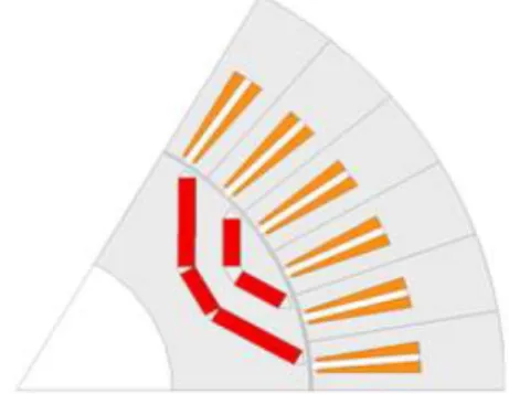
(1) The design size includes the housing and is limited to Ø480 mm. The stator diameter was Ø350 mm, the rotator diameter was Ø210 mm, and the air gap length was set to 1 mm. To maximize the flux-wakening control area that utilizes high-efficiency and high-output magnetic reluctance torque, a double-layer type permanent magnet shape was designed.[6]
For high-performance torque, a high-magnetic reluctance torque is required; an Lq–Ld design is necessary for this purpose. To design Lq to be as large as possible, a double-layer permanent magnet rotor structure was utilized to secure the q axis magnetic circuit of the permanent magnet rotor without saturation. Six design parameters were applied to configuration and arrangement of the double-layer permanent magnet rotor model: the angles of the first and second layers, angle applicable to the pole-arc proportion, heights of the first and second permanent magnet layers, and entrance width of the q axis magnetic circuit. The Taguchi method was used to optimize the design of the permanent magnet.[7]
Based on the productivity and efficiency shown in Fig. 1, a double-layer permanent magnet rotor form was designed that satisfies the voltage limitation of 380 Vrms.
Fig. 1. Permanent magnet of double-layer type.
2.2 motor structural analysis and design
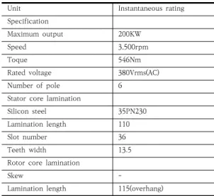
Unit Instantaneous rating
Specification
Maximum output 200KW
Speed 3,500rpm
Toque 546Nm
Rated voltage 380Vrms(AC)
Number of pole 6
Stator core lamination
Silicon steel 35PN230
Lamination length 110
Slot number 36
Teeth width 13.5
Rotor core lamination
Skew -
Lamination length 115(overhang) Table 2. Final design motor specification
By utilizing the Lorentz force between the magnetic field and current, the electric motor generates rotary power to convert electric energy to mechanical energy.[8-9] In this process, the electric motor generates necessary losses such as hysteresis, eddy current, and resistance loss.[10-11]
However, additional losses, such as those arising from heat, vibration, and noise, occur; loss due to heat makes up the largest percentage and directly raises the temperature of the electric motor. This changes the electromagnetic properties of the magnetic material or conductor, which decreases the electric motor’s life. Heat transfer through conduction raises the electric motor temperature through loss inside the electric motor, and heat energy is conducted from inside the object to its surface. Convection heat transfer is generated on the side in contact with a solid, gas, or liquid refrigerant. Heat energy due to the electric motor’s internal loss is emitted through convection heat transfer. Using the Motor CAD Heat Analysis Program on the designed electric motor, as shown in Table 2, a coolant was applied, as shown in Table 3, and the electric motor was operated for 4 h. The analysis results
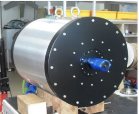
are shown in Fig. 2. The analysis results revealed that heat generated before 2 h of electric motor operation at 20 and 60 ℃ continued for 4 h until the end of the experiment. Therefore, no large problems were found with actually applying the design to a vehicle; the product is shown in Fig.
3.
Unit Value
Inlet temperature 20 or 60℃
Fluid volume flow rate 0.03 ㎡/s Thermal conductivity 0.6 w/m·k
Density 1,000 g/㎖
Cp 4,187
Kinematic viscosity 1.005e-6 ㎡/s Dynamic viscosity 0.001005 ㎡/s
Pr-Prandtl number 7.013
Table 3. cooling water heating property
(a) 20℃ cooling water
(b) 60℃ cooling water Fig. 2. Motor heating flow analysis
Fig. 3. Applying the motor
3. Transmission structure design
3.1 Transmission mechanism design
Fig. 4. Shift gears mechanism
Planetary gears were used for the transmission mechanism design of a dual-ring gear transmission structure.[12-14] Two planetary gear sets, each having a gear ratio for a single carrier, are shown in Fig. 4 where the first transmission is in neutral. The first clutch B1 is operated by fixing the first ring gear R1. The power input in the sun gear S is delivered to the first planetary gear P1 and decelerated by becoming the output to carrier C. To select the second transmission, the first clutch B1 is released, and the second clutch B2 is operated to fix the second ring gear R2. The sun gear S power is decelerated by becoming the output to the carrier C via the second planetary gear P2. Considering the transmission volume, the number of sun gear teeth of the developed transmission was set to
12; the fixed ring gear was assumed to be as shown in Table 4. The deceleration ratio was calculated by applying Eq. (2). The specifications were then designed as shown in Table 5.
(sun gear)S R(ring
gear) C
(carrier) 1 C fixed, S
rotate with w
0
2 Rotate all +
S fixed1+2 =
0
Table 4. Calculation of reduction gear ratio
(2)
Number of teeth
Unit 1st gear 2nd gear
Sun gear 12 12
Planetary gear 32 11
Ring gear 82 36
Reduction gear ratio 7.5 4
module 2
Table 5. Reduction gears specification
3.2 Transmission reliability test and design
Gear RPM Sun gear Planet gear Ring gear
SF SH SF SH SF SH
1st
3,500 1.19 0.69 0.85 0.77 1.17 1.12 4,000 1.35 0.74 0.97 0.83 1.29 1.18 5,000 1.67 0.82 1.19 0.92 1.5 1.28
6,000 1.96 0.9 1.41 1 1.69 1.36
6,562 2.13 0.94 1.52 1.04 1.77 1.4
2nd
3,500 1.53 0.68 0.53 0.69 1.79 0.65 4,000 1.75 0.72 0.6 0.74 2.01 0.69 5,000 2.18 0.81 0.75 0.83 2.44 0.77 6,000 2.6 0.89 0.89 0.91 2.84 0.83 7,000 3.01 0.96 1.03 0.98 3.22 0.89 8,000 3.41 1.02 1.17 1.04 3.57 0.94
9,000 3.8 1.08 1.31 1.1 3.89 0.98
10,000 4.18 1.14 1.44 1.16 4.13 1.02 Table 6. Root safety(SF) and flank safety(SH)
according to the RPM
The KISSsoft program was used for the designed gear to calculate the root and flank safety depending on the rotations of the first and second shifts for an output of 200 kW, as shown in Table 6. The calculation results showed that the gear root and flank safety were in the acceptable range, so there were no problems with application.
Gear Speed
(km/h) Motor (rpm) Transmission
(rpm) Efficiency
st1
5.2 1,000 133.3 97.55
10.4 2,000 266.7 97.87
15.7 3,000 400.0 98.03
18.3 3,500 466.7 98.09
20.9 4,000 533.3 98.19
26.1 5,000 666.7 98.35
31.3 6,000 800.0 98.46
34.3 6,562.5 875.0 98.52
nd2
34.3 3,500 875.0 97.01
48.9 5,000 1,250 97.41
58.7 6,000 1,500 97.55
68.5 7,000 1,750 97.62
78.3 8,000 2,000 97.68
88.1 9,000 2,250 97.74
97.9 10,000 2,500 97.79
Table 7. Gear meshing efficiency
Fig. 5. Manufacture the transmission The gear meshing efficiency depends the speed; Table 7 shows the results obtained in the research. The gear meshing efficiency is the meshing efficiency of the net gear excluding the heat, bearing friction, and clutch friction losses.
The test results revealed that the gear meshing efficiency increased with the number of revolutions for the first shift rather than for the
second shift. As all of the efficiencies exceeded 97%, application with a high meshing efficiency was concluded to be possible. Fig. 5 shows the optimized transmission based on the above design and inspection.
4. Motor-Transmission integration
For the actuator system applied to the electric vehicle, the motor and transmission were isolated;
thus, technology integrating the developed motor and transmission was required. Once these are integrated, the connector between the input and output can be simplified, and the cooling system’s volume can be reduced. The size and weight were reduced, so the design and attachment were easy. In general, manufacturing costs can be reduced by simplifying the process.
Therefore, technology to integrate the developed motor and transmission was researched.
4.1 Integral Spline Design and Structural
Analysis
Unit Mark Value
Hub addendum D1 31mm
Shaft addendum D2 34.5mm
Length L 28mm
Efficiency η 0.75
Teeth Z 16
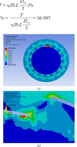
Toque T 546Nm
Effective diameter Dm 32.75mm
Table 8. Design of spline specification
Based on the convenience and efficiency of transmission repair, a spline was designed to integrate the motor and transmission. The spline specifications are shown in Table 8; the motor torque in formula (3) was used to calculate the maximum stress added to the spline, as shown in formula (4). The calculation confirmed that a stress of 56.7 MPa was received. As an additional inspection, the same specifications were plugged into ANSYS Workbench 14.0 for FEM analysis. In
the FEM analysis, torque was applied to the axis section of the spline to induce more intense conditions, and stress analysis was performed using the same specifications shown in the formula. As shown in Fig. 6, the resulting stress was equally distributed over each spline tooth, and the stress tendencies of each tooth were similar. The maximum stress occurred at the spline’s tooth root and was 136.32 MPa. The results of the progression formula analysis with the designed specifications differed from those of the FEM analysis. In the FEM analysis, an intense condition was assumed when the motor torque was given to the spline axis section. As both values showed values less than the yield strength of the steel material, it was concluded that there would be no problem with application.
(3)
(4)(a)
(b) Fig. 6. Spline FEM analysis
4.2 Motor-transmission integration module
manufacture
Fig. 7. Spline design
In order to integrate the developed motor with the transmission, shown in Fig. 7, the spline hub was designed on the transmission shaft. A module was attached in the vehicle, and an adapter as long as the spline axis was installed in the motor and transmission to stabilize them and avoid the problem of axis deviation. Through integration using the spline, a motor and transmission axis were manufactured as shown in Fig. 8.
Fig. 8. Manufacture the motor-transmission integral
5. Conclusion
In this study, a motor and transmission were developed that can be applied to commercial electric vehicles, and dual modules like the motor and transmission were integrated. The following results were obtained from the structurally improved model.
1) Current motors are impossible to apply to commercial electric vehicles that weigh over
3.5 tons. Therefore, a double-layer permanent magnet rotor was developed in this study that is capable of 3500 rpm, 200 kW class maximum output, and 546 Nm torque motor.
2) The motor showed energy losses, most significantly through heat; this factor reduces the operating life. To determine the energy loss from convection heat transfer inside the developed motor, the test conditions of applying 20 and 60 ℃ coolant were applied.
The heat generated 2 h before motor operation continued for 4 h after the completion of the experiment. Therefore, actual application of the developed motor was concluded to be possible.
3) Dual ring type planetary gear was applied for the transmission, which was designed to have a deceleration ratio of 7.5 in the first shift and 4 in the second shift.
4) To confirm the applicability of the designed gear, the root and flank safety of the gear were confirmed experimentally. The experimental results for the gear meshing efficiency showed that the first transmission was more efficient than the second transmission with increasing rotation.
5) For motor and transmission integration, a spline was designed in the motor axis and hub of the transmission axis. FEM analysis based on the designed specifications revealed that the stress was distributed equally over each spline’s tooth, and a maximum stress of 136.32 MPa was generated at the root of the tooth.
6) After each aspect was verified experimentally, an all-in-one motor-transmission module was designed and manufactured.
References
[1] Wikipedia, European emission standards, http://en.
wikipedia.org/wiki/European_emission_standards#Em ission_standards_for_light_commercial_vehicles, 2009.
[2] C. Ma, J. Kang, W. Choi, M. Song, J. Ji and H. Kim, “A comparative study on the power characteristics and control strategies for plug-in hybrid electric vehicles”
International Journal of Automotive Technology, vol.
13, No. 3, pp. 505-516, 2012.
DOI: http://dx.doi.org/10.1007/s12239-012-0048-x [3] Kim. J, Kim. N, Hwang. S, Hori. Y and Kim, H, “Motor
control of input-split hybrid electric vehicles”
International Journal of Automotive Technology, vol.
10, No. 6, pp. 733-742, 2009.
DOI: http://dx.doi.org/10.1007/s12239-009-0086-1 [4] Y. L. Chen, S. A. Liu, J. H. Jiang, T. Shang, Y. K. Zhang
and W. Wei, “Dynamic analysis of energy storage unit of the hydraulic hybrid vehicle” International Journal of Automotive Technology, vol. 14, No. 1, pp.
101-112, 2013.
DOI: http://dx.doi.org/10.1007/s12239-013-0012-4 [5] Boukehili. A, Zhang. Y.T, Zhao. Q, Ni. C.Q, Su. H.F and
Huang, G.J, “Hybrid vehicle power management modeling and refinement” International Journal of Automotive Technology, vol. 13, No. 6, pp. 987-998, 2012.
DOI: http://dx.doi.org/10.1007/s12239-012-0101-9 [6] Ombach, Grzegorz, “Electromechanical system with
IPM motor used in electric or hybrid vehicle” Compel, Vol. 30, No. 1. pp. 137-150, 2011.
DOI: http://dx.doi.org/10.1108/03321641111091485 [7] Dehnad, K, “Quality Control, Robust Design and the
Taguchi Method” International Biometric Society. Vol.
45, No. 4, pp. 1345, 1989.
DOI: http://dx.doi.org/10.2307/2531803
[8] Ribaric, Marijan. S us ters ic, Luka, “Expansions in Terms of Moments of Time-Dependent Moving Charges and Currents” SIAM Journal on Applied Mathematics. Vol.55, No. 3, pp. 593-624, 1995.
DOI: http://dx.doi.org/10.1137/S0036139992241972 [9] Zhu, Jing, “Principle and Characteristic of Lorentz
Force Propeller” Journal of Electromagnetic Analysis and Applications. Vol. 1, No. 4, pp.229-235, 2009.
DOI: http://dx.doi.org/10.4236/jemaa.2009.14034 [10] Shinji Shinnaka, “A new separate-identification
method of two stator equivalent core-loss resistances corresponding to hysteresis and eddy-current losses for parallel-type mathematical models of AC motors”
Electrical Engineering in Japan. Vol. 143, No. 4, pp.
50-63, 2003.
DOI: http://dx.doi.org/10.1002/eej.10152
[11] Belahcen, E. Dlala, K. Fonteyn and M. Belkasim, “A posteriori iron loss computation with a vector hysteresis model” Compel. Vol. 29, No. 6, pp. 1493-1503, 2010.
DOI: http://dx.doi.org/10.1108/03321641011078562 [12] Inalpolat. M, Kahraman, “A Dynamic modelling of
planetary gears of automatic transmissions” Proceedings of the Institution of Mechanical Engineers. Vol. 222, No.
k3, pp. 229-242, 2008.
DOI: http://dx.doi.org/10.1243/14644193JMBD138
[13] F. I. Plekhanov, V. S. Kuznetsov, “Deformability of elements of a planetary gear transmission” Russian Engineering Research, Vol. 30, No. 6, pp.557~560, 2010.
DOI: http://dx.doi.org/10.3103/S1068798X10060055 [14] W. Shi, C. W Kim, C. W Chung, and H. C Park,
“Dynamic modeling and analysis of a wind turbine drivetrain using the torsional dynamic model”
International Journal of Precision Engineering and Manufacturing, Vol. 14, No. 1, pp.153~159, 2013.
DOI: http://dx.doi.org/10.1007/s12541-013-0021-2
Se-Hoon Oh [Regular member]
• 1983. 2. : Seoul National University. Department of Mechanical Engineering. Master of Engineering.
• 1991. 2. : Imperial College.
Doctor of Engineering.
• 1985. 3. : Korea Institute of Mahinery & Materials.
Robot Engineering Laboratory. head of Labotaory.
• 1993. 3. : Chung-Ang University. Department of Mechanical Engineering. Professor.
<Research Interests>
Design of reducer, Design of Gear Tooth Profile
Kwang-Wook Youm [Regular member]
• 2010. 8. : Chung-Ang University.
Department of Mechanical Engineering. Master of Engineering.
• 2014. 8. : Chung-Ang University.
Department of Mechanical Engineering. Doctor of Engineering.
• 2014. 3 : Dong-Ju University. Department of Automotive and Mechanics. Professor.
• 2018. 9. : Hanyangcyber University. Department of Mechanical and Automotive Engineering. Professor.
<Research Interests>
Automotive Structure, Design of Transmisson, EV System