OPTIMIZATION OF LAMINATED COMPOSITE FOR BUCKLING PERFORMANCE
Hee Keun Cho*1
1Satellite Technology Research Center Korea Advanced Institute of Science and Technology 373-1, Guseong-dong, Yuseong-gu, Daejon, 305-701, Korea
Abstract
Motivated by needs such as those in the aerospace industry, this paper demonstrates ability to significantly increase buckling loads of perforated composite laminated plates by synergizing FEM and a genetic optimization algorithm (GA). Plate geometry is discretized into specially-developed 3D degenerated eight-node shell isoparametric layered composite elements. General shell theory, involving incremental nonlinear finite element equilibrium equation, is employed. Fiber orientation within individual plies of each element is controlled independently by the genetic algorithm. Eigen buckling analysis is performed using the subspace iteration method. Available results demonstrate the approach is superior to more conventional methodologies such as modifying ply thickness or the stacking sequence of individual rectilinear plies having common fiber orientation through the plate.
INTRODUCTION
Associated with their favorable responses, composites find widespread utilization. However, geometric discontinuities such as holes or notches can erode structural performance. Motivated by this situation, the present paper is directed at enhancing the buckling loads of perforated composite laminated plates by synergizing FEM and a genetic optimization algorithm (GA) [1-4].
Several researchers previously utilized a GA to optimize laminated composites. Holland [5], Goldberg [6] and Bethke formulated engineering basis for implementing GA, while applications to composite design were conducted by Haftka, Gürdal, Hajela, et. al. [3,7,8]. The objective of this work is to maximize buckling loads of perforated laminated composite plates by controlling locally fiber orientation in the respective plies of each small discrete area (finite element) making up a structure.
Design variables are the fiber orientation of individual plies within each element. This study involved developing an integrated optimization program, named COMBO8 (COMposite Buckling Optimization code: 3-D 8node degenerated shell element), which combines a FEA module, nonlinear static and eigen buckling of laminated composites, and a GA module to compute the objective function simultaneously.
ANALYTICAL FORMULATION OF LAMINATED COMPOSITE Finite Element Formulation
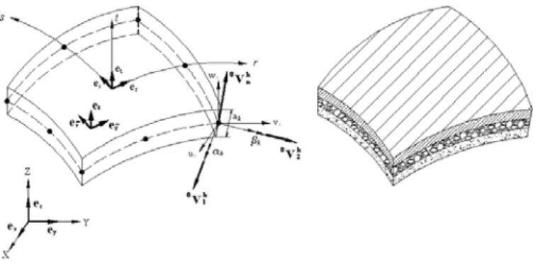
Motivated by the current desire to synergize FEA and optimization abilities, a general serendipity isoparametric degenerated 8-node shell element was specially developed for the present laminated composite study. Based on general shell theory, the element is suitable for modeling curved shallow layered composite plates.
Figure 1 - 8-node degenerated shell element
The virtual work principle is applied to the deformable shell under arbitrary static equilibrium condition at time t. The external virtual work at time t, tR, can be expressed as
(1)
where 0tSijis the 2nd Piola-Kirchhoff stress tensor or nominal (engineering) stress and 0tε is strain ij [9]. According to this stress definition, the real force applied to the deformed body has been transformed to the initial state and divided by initial area. The relationship between the 2nd Piola- Kirchhoff stress tensor and Green-Lagrange strain tensor, 0tε , is ij
(2)
such that t0Cijrs represents material properties tensor. For linear elastic isotropy, it can be written as
(3) with κand μ being the Lame constants, κ =E/(1+υ)(1 2 )− υ and μ=E/ 2(1+υ), and δ is ij the Kronecker delta.
EXAMPLES
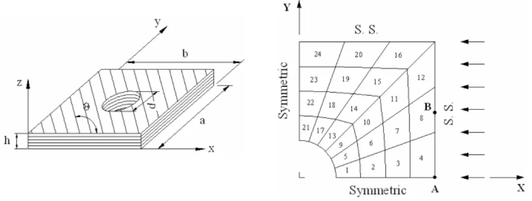
The illustrative example of a uniaxially-loaded 254-mm by 254-mm (a=b=10" by 10") square laminated composite containing a central circular hole (radius = 42.35mm) is analyzed, Figs. 2 and 3.
Geometric, loading and material symmetry enables modeling only one quarter of the component.
Symmetric displacement boundary conditions are applied to the horizontal and vertical lines of symmetry.
The purpose of this analysis is to maximize the buckling resistance (load: N/mm = load per in- plane distance) by controlling locally fiber orientation from element-to-element and from ply-to-ply within an element. Since the fiber angle is uniform within each ply of an element, the material within a
0
0
0 0 ( )
t t t
ij ij
R= ∫V Sδ ε d V
0 0 0
t t t
ij ijrs rs
S = C ε
( )
0 t
ijrs ij rs ir js is jr
C =κδ δ +μ δ δ +δ δ
ply of an element can be modeled as being orthotropic. Three sets of lay-ups ( [ ]08 S , [±45 / 06 S] and[( 45 / 0 / 90)± 2 S] ) are studied and the three lay-ups, [ ]T8 S, [±45/T6 S] and [T / T ]4a 4 Sb , were optimization. Notation “T” in the stacking sequence denotes a layer whose fiber orientations have been optimized within individual elements by GA. The analysis optimized the groups of plies (T8of
[ ]T8 S, T6of [±45/T6 S] , and each of T and 4a T of 4b [T / T ] ) to have the same fiber orientation. 4a 4 Sb
Figure 2 - Geometry, finite element discretization and applied boundary conditions (a = b = 254mm, d
= 84.7, h = 2mm; S.S.= simply supported)
Figure 3 - Sixteen-ply composite laminate
Table 1 Material properties
Properties Graphite Epoxy (Gr/E)
E11 138 GPa
E22 = E33 8.96 GPa
υ12 = υ13 0.3
υ23 0.45
G12 =G13 7.1 GPa
G23 = E22/2(1+ υ23) 3.09 GPa
RESULTS
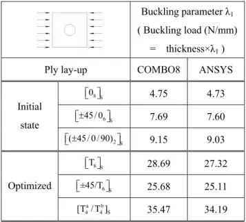
Results of the optimized perforated [ ]T8 S, [±45/T6 S] and [T / T ]4a 4 Sb laminates are presented in Table 2. The respective buckling parameters, λ , for the optimized laminates by GA are 28.69 1 ([ ]T8 S), 25.68 ([±45/T6 S] ) and 35.47 ([T / T ] ). 4a 4 Sb [ ]T8 S is inversely stronger than [±45/T6 S]
buckling-wise.
Table 2 - Comparison of buckling parameter, λ1, for initial and optimized perforated composite plates
Buckling parameter λ1
( Buckling load (N/mm)
= thickness×λ1 )
Ply lay-up COMBO8 ANSYS
08 S
⎡ ⎤⎣ ⎦ 4.75 4.73
45/ 06 S
⎡± ⎤
⎣ ⎦ 7.69 7.60
Initial state
( 45/ 0/ 90)± 2 S
⎡ ⎤
⎣ ⎦ 9.15 9.03
T8 S
⎡ ⎤⎣ ⎦ 28.69 27.32
±45/T6 S
⎡ ⎤
⎣ ⎦ 25.68 25.11
Optimized
a b
4 4 S
[T / T ] 35.47 34.19
Such increases in buckling resistance are significant since a structure’s compressive strength, and therefore its design, applications and ultimately its weight, can depend on allowable buckling load.
Table 2 also contains ANSYS predictions, based on the optimized fiber angles computed by COMBO8.
Figures 4, 5 and 6 show the local fiber orientation of the optimized plies for each of the [ ]T8 S, [±45/T6 S] and [T / T ]4a 4 Sb composites. Comparing Figs. 4, 5 and 6 with each other illustrates that the applied GA method results in similar fiber orientations near the external boundary of the three cases considered, but somewhat different orientations closer to the hole.
Figure 4 - Buckling mode(λ ) and fiber orientation throughout 16 plies of individual elements of 1 optimized [ ]T8 S laminate of Table 2
Figure 5 - Buckling mode(λ ) and fiber orientation through middle 12 plies of individual elements of 1 optimized [±45/T6 S] laminate of Table 2
Figure 6 - Buckling mode(λ ) and fiber orientation throughout the outer four plies, 1 [T ]a ,and inside eight plies,[T ]b , of individual elements of optimized [T / T ]4a 4 Sb laminate of Table 2
Figures 4 through 6 reveal several important facts. First, it is clear that the optimization algorithm tries to achieve as many collapsing points as possible within the plate by controlling fiber arrangements. For example, [ ]T8 S and [T / T ]4a 4 Sb of Figs. 4 and 6, respectively, exhibit two collapses points, one near the central hole and one away from the hole.
CONCLUSIONS
Most previous optimization buckling studies of composite laminates are based on plate theory [13-15].
The present extension to three-dimensional elastic theory overcomes limitations of plate theory, thereby extending the method’s applicability. An eight-node degenerated shell finite element formulation, which includes eigen and buckling solutions, is presented for buckling analysis of perforated composite laminates. The buckling load is maximized here by optimizing fiber direction within plies of individual elements using GA. This is achieved by synergizing GA optimization and FEM capabilities into a software program called COMBO8. Results demonstrate the present method’s ability to out perform earlier conventional design methods.
ACKNOWLEDGEMENTS
The author wish to acknowledge the support of SaTReC (Satellite Technology Research Center) of Korea Advanced Institute of Science and Technology
[T ]b
[T ]a
REFERENCES
[1] Todoroki A. and Sasai, M., “Improvement of design reliability for buckling load maximization of composite cylinder using genetic algorithm with recessive-gene-like repair”, JSME internal journal Series A, 42, 530-536 (1999).
[2] Spallino R. and Thierauf G., “Thermal buckling optimization of composite laminates by evolution strategies”, Computers & structures, 78, 691-697 (2000).
[3] Riche L.R. and Haftka R.T., “Optimization of laminate stacking sequence for buckling load maximization by genetic algorithm”, AIAA journal, 31, 951-956 (1993).
[4] Kang J.H. and Kim C.G., “Minimum weight design of compressively loaded composite plates and stiffened panels for post-buckling strength by genetic algorithm”, Composite structures, 69, 239-246 (2005).
[5] Holland J.H., “Genetic algorithms and machine learning”, Machine learning, 3, 95-99 (1998).
[6] Goldberg D.E., Genetic algorithms in search optimization & machine learning. (Addison Wesley, 1989).
[7] Soremekun G., Gürdal Z., Haftka R.T. and Watson L. T., “Composite laminate design optimization by genetic algorithm with generalized elitist selection”, Computers & structures, 79, 131-143 (2001).
[8] Adali S., Richter A., Verijenko V.E. and Summers, E.B., “Optimal design of hybrid laminates with discrete ply angles for maximum buckling load and minimum cost”, Composite structures, 32, 409-415 (1995).
[9] Bathe K.J., Finite element procedures in engineering analysis. (Prentice Hall, New York, 1982).
[10] Cho H.K. and Rowlands R.E., “Minimizing stress concentrations in laminated composites by genetic algorithm”, IMECE2005-81005, Orlando (2005).
[11] Reddy J.N., Mechanics of laminated composite plates: theory and analysis. (CRC press, 1997).
[12] Staab G.H., Laminar composites. (Butterworth Heinmann, 1999).
[13] Kim K.D., “Buckling behavior of composite panels using the finite element method”, Composite structures, 36, 33-43, (1996).
[14] Kogiso K., Watson L.T., Gurdal Z., Haftka R.T., and Nagendra S., “Minimum thickness design of composite laminates subject to buckling and strength constraints by genetic algorithms,” Proceedings of the 35th AIAA/ASME/ASCE/AHS/ASC Structures, Structural Dynamics & Materials Conference, . 4, 2257-2275, (1994).
[15] Lin C.C. and Lee Y.J., “Stacking sequence optimization of laminated composite structures using genetic algorithm with local improvement”, Composite structures, 63, 339-345, (2004).
![Figure 5 - Buckling mode( λ ) and fiber orientation through middle 12 plies of individual elements of 1 optimized [ ±45/T 6 S] laminate of Table 2](https://thumb-ap.123doks.com/thumbv2/123dokinfo/5204808.353760/5.892.277.627.169.309/figure-buckling-orientation-middle-individual-elements-optimized-laminate.webp)
