• 검색 결과가 없습니다.

The FEM Analysis of Recessing Location on the Stress Distribution in Aluminum Double Lap Joint

N/A
N/A
Protected

Academic year: 2021

Share "The FEM Analysis of Recessing Location on the Stress Distribution in Aluminum Double Lap Joint"

Copied!
5
0
0

로드 중.... (전체 텍스트 보기)

전체 글

(1)

The FEM Analysis of Recessing Location on the Stress Distribution in Aluminum Double Lap Joint

You Min

, Yan Zhanmou, Zheng Xiaoling, and Yu Haizhou

College of Mechanical and Material Engineering, China Three Gorges University Yichang, 443002, China (Received November 10, 2006; Accepted November 21, 2006)

Abstract: The elasto-plastic finite element method (FEM) was used to investigate the effect of off-center recessing location (8 mm length) on the stress distribution in the lap zone of adhesively bonded aluminium double lap joint. The results from simulation showed that the effect of off-cent recessing in bondline of double lap joint in the mid-bondline is not evidently to stress distribution in mid-bondline but the peak stresses both in mid-bondline and in the interface near the adherend side of the joint may increase markedly when an 8 mm length recessing was arranged symmetrical to the point of x =18 mm.

When shifting an 8 mm length recess from near left end to the right end of the lap zone, all the highest peak stresses in the mid-bondline occurred under the condition of recess arranged symmetrical to the point of x = 6 mm.

Keywords: aluminium, off-center recessing, double lap joint, stress distribution, FEM

1. Introduction

1)

Bonding technology is applied widely today in almost all the industry of the world accounting for its high strength-weight ratio, low cost and high efficiency and one branch of it named intermittent bonding appeared in recent years [1,2]. It is defined as a joint bonded by in- termittent adhesive layer so that there is at least one gap (or more gaps, several recesses) in the adhesive layer. In general, the studies related to the recessing in bondline on the mechanical properties of adhesively bonded joint was in a viewpoint of treating the recess- ing as defect in the joint and mainly focused it on sin- gle lap joint [3-5]. Olia [3] reported that the effect of recess on the peak stresses of peel stress and shear stress in single lap joint under bending was little, unless it was sufficiently close to the end of lap zone. Lang [4] discussed the result using FEM that the effect of re- cess on the peak stress of joint under tensile load could be negligible. Results of De Moura [5] from experiment and numerical simulation showed that the influence of recess length and width on the nominal strength of joint was little. In our studies the intermittent (or recessed)

Corresponding author: e-mail: [email protected]

bonding was considered as an advanced technology and showed that reasonable intermittent layer may increase the actual strength through experiment and FEM [1,2]. It was known that the use of double lap joint is broadly today in aeronautical industry [6] for avoiding the great eccentricity of stress in single lap joint. Up till now, there is scarcely literature related about double lap joint with recess. In this work the authors have investigated the effect of intermittent bonding on the stress dis- tribution of double lap joint through elasto-plastic FEM.

2. Finite Element Model and Mesh

The model and mesh were built using the ANSYS fi-

nite element software. The aluminium specimen (100

mm

L

× 25 mm

W

× 2 mm

T

) was prepared in accordance

with GB7124-1986 as shown in Figure 1 and bonded

with 0.2 mm-thick epoxy adhesive. The generalized

plane strain element PLANE183 was used for both ad-

herend and adhesive. The bondline was divided into four

layers along the direction of thickness, and the element

length of fillets and the neighboring adherend is set as

0.05 mm. Fillets were divided into triangular element

while the others divided into quadrilateral one as shown

in Figure 2. The load applied was taken as 150 MPa

(2)

Figure 1. Finite element model.

(a) (b)

Figure 2. Finite element mesh: (a) overlap and (b) deta il.

(7.5 KN) and the boundary conditions of the model are also shown in Figure 1. All the stresses data were ob- tained from mid-bondline y = 1.1 mm.

3. Finite Element Analysis

2.1. Influence of Recess

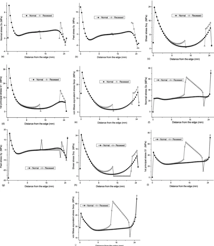
The effect of recess on the stress distribution in the mid-bondline of the joint is shown in Figure 3 where 8 mm length recess located symmetrical to the point x = 18 mm. From Figure 3 it can be seen the effect of re- cess on the peak stress in the mid-bondline of the joint was very small but the stress at the edge of recess in- creased evidently. The peak stresses of double lap joint appeared at the ends of lap zone and the maximum

the effect of recess could be negligible. Where there is no adhesive (the gap existed), there is no any stress component at all in the mid-bondline. The peak stresses of double lap joint appear at the ends of lap zone, and the maximum is on the left, while the stresses in the middle of lap zone, offsetting to right, are very small, almost equal to zero, bearing little load. So the effect of gap could be negligible. From Figure 3(f) to Figure 3(j) the same tendency of the stress in the adherend along the lap zone is shown and relative higher value of peak stress (over 60 MPa) appears in the curve represented the stress distribution of Sx, S1 and Seqv. In Fig. 3(f) the normal stress at the point x = 14.5 mm has in- creased by 140.7% and at the right edge of the end (x

= 25 mm) increased by 6.6%. For the stress distribution of Sy and Sxy in adherend corresponding to the gap in adhesive layer the stress is below the one of no gap ex- isted in the adhesive layer and the peak value of stress appears at the point near the edge of the gap. From Figure 3 it is clearly that the load bearing ability of the double lap joint should not be affected by an 8 mm length gap arranged symmetrical to the point x = 18 mm. In other words, the effect of the gap under such condition may be negligible.

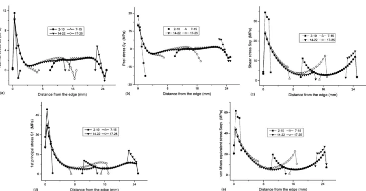
2.2. Influence of Recess Position

When the recess length kept as 8 mm the effect of recess position on the stress distribution was investigated.

The distribution of the normal stress Sx, peel stress Sy,

shear stress Sxy, 1st principal stress S1 and von Mises

equivalent stress Seqv in the mid-bondline of double lap

joint is shown in Figure 4. The peak stress of Sxy, S1

or Seqv increased markedly when the recess located

closely to the left end of lap zone (location: x=2 to 10

mm). When shifting the 8 mm length recess from near

left end to the right end of the lap zone, all the highest

peak stresses occurred under the condition of recess ar-

ranged symmetrical to the point of x = 6 mm. The va-

(3)

(j)

Figure 3. The effect of 8 mm length gap centered at x= 18 mm on the stresses distribution in double lap joint: normal

stress Sx in (a) mid-adhesive and (f) adherend; peel stress Sy in (b) mid-adhesive and (g) adherend; shear stress Sxy in (c)

mid-adhesive and (h) adherend; 1st principal stress S1 in (d) mid-adhesive and (i) adherend and von Mises equivalent stress

Seqv in (e) mid-adhesive and (j) adherend.

(4)

Figure 4. The effect of position of recess on the stress distribution in double lap joint within the mid-bondline: (a) normal stress Sx; (b) peel stress Sy; (c) shear stress Sxy; (d) 1st principal stress S1 and (e) von Mises equivalent stress Seqv.

Figure 5. The effect of 8 mm length recess position on the stress distribution in double lap joint from left to right: shear stress Sxy of 2∼10 mm (a), 7∼15 mm (b), 14∼22 mm (c) and 17∼25 mm (d); peel stress Sy of 2∼10 mm (e), 7∼15 mm (f), 14∼22 mm (g) and 17∼25 mm (h); von Mises equivalent stress Seqv of 2∼10 mm (i), 7∼15 mm (j), 14∼22 mm (k) and 17∼25 mm (m).

riety of peak stresses was very small as the recess transferred in a wide range from the left part to the right end of lap zone in other three cases. For under- standing the effect of recess position better the contour diagrams presenting the distribution of the stress Sy, Sxy and Seqv were shown in Figure 5 and the detail contour

diagram of peel stress Sy in the left part of lap zone

shown in Figure 6. In Figure 4(a) the normal stress Sx

at the point x = 0.5 mm the peak value was about 34.4

MPa for a recess from x = 2 mm to x = 10 mm

(recess symmetrical to the point x = 6 mm) as at least

41.6% higher than the other three peak values (recess

(5)

Figure 6. The detail contour diagram of peel stress Sy in the left part of lap zone: (a) 2∼10 mm, (b) 7∼15 mm and (c) 17

∼25 mm.

symmetrical to the point x = 11 mm, x = 18 mm and x = 21 mm respectively). From Figure 5 it could be seen the contour lines are more complex for the condition of the recess located near the left end of the lap zone in Figure 5(a), Figure 5(e) and Figure 5(i). But in Figure 6 the highest values of peel stress Sy (about 94.3 MPa, recess symmetrical to the point x = 11 mm) appeared at the toe of the right fillet in Figure 6(b) and the lower one (about 81.7 MPa, symmetrical to the point x = 6 mm) occurred in Figure 6(a). When the recess located at the right end of lap zone (recess symmetrical to the point x = 21 mm) there is no adhesive at all in the right part of lap zone, which means to reduce the lap length of the joint.

4. Conclusion

The effect of 8 mm length recess and its position on the stress distribution in the adhesively bonded alumi- nium double lap joint has been investigated using elas- to-plastic finite element method and the following con- clusions have been drawn:

The effect of 8 mm length off-center recess (arranged symmetrical to the point x = 18 mm) is not evidently on the peak stresses of double lap joint in the mid-bondline and the ultimate load of the joint might not be decreased markedly.

The peak stresses decrease gradually first and then in- crease a little again when the 8 mm length recess trans- fers from near the left end of lap zone to right one and the variety of peak stress is negligible. All the peak stresses reach their lowest values when an 8 mm length

recess was arranged symmetrical to the point of x = 18 mm, and the peak stresses increase markedly when re- cess was located closed to the left end of lap zone (arranged symmetrical to the point of x = 6 mm).

References

1. X. L. Zheng, M. You, Y. Zheng, et al., The effect of off-center recessing on the strength of adhesively bonded single-lap joint. In Proceedings of 7

th

Int.

Conf. on Structural Adhesives in Engineering (SAE VII, 13-15 July 2004, Bristol, UK),IOM Communi- cations Ltd. London,p.171-174 (2004).

2. F. R. Kong, M. You, X. L. Zheng, et al., Effect of recessed bonding on stress distribution and strength of adhesively bonded joints [J]. Aerospace Materials

& Technology, 2004(4): 39-43.

3. M. Olia and J. N. Rossetos. Analysis of adhesively bonded joints with gaps subjected to bending. Int. J of Solids and Structures, 33(18): 2681-2693 (1996).

4. T. P. Lang and P. K. Mallick. The effect of recess- ing on the stresses in adhesively bonded single-lap joints. International Journal of Adhesion & Adhesi- ves, 19(4): 257-271 (1999).

5. M. F. S. F. de Moura, R. Daniaud, and A. G.

Magalhaes, Simulation of mechanical behaviour of composite bonded joints containing strip defects. Int.

J of Adhesion & Adhesives, 26(6): 464-473 (2006).

6. T. Keller and T. Vallee, Adhesively bonded lap

joints from pultruded GFRP profiles. Part I: stress-

strain analysis and failure modes. Composites: Part

B, 36: 331-340 (2005).

수치

Figure 2. Finite element mesh: (a) overlap and (b) deta il.
Figure 3. The effect of 8 mm length gap centered at x= 18 mm on the stresses distribution in double lap joint: normal  stress Sx in (a) mid-adhesive and (f) adherend; peel stress Sy in (b) mid-adhesive and (g) adherend; shear stress Sxy in (c)  mid-adhesiv
Figure 4. The effect of position of recess on the stress distribution in double lap joint within the mid-bondline: (a) normal  stress  Sx; (b) peel stress Sy; (c) shear stress Sxy; (d) 1st principal stress S1 and (e) von Mises equivalent stress Seqv.
Figure 6. The detail contour diagram of peel stress Sy in the left part of lap zone: (a) 2∼10 mm, (b) 7∼15 mm and (c) 17

참조

관련 문서

웹 표준을 지원하는 플랫폼에서 큰 수정없이 실행 가능함 패키징을 통해 다양한 기기를 위한 앱을 작성할 수 있음 네이티브 앱과

_____ culture appears to be attractive (도시의) to the

The index is calculated with the latest 5-year auction data of 400 selected Classic, Modern, and Contemporary Chinese painting artists from major auction houses..

1 John Owen, Justification by Faith Alone, in The Works of John Owen, ed. John Bolt, trans. Scott Clark, "Do This and Live: Christ's Active Obedience as the

This study was performed to confirm the effect of the stress distribution on short implant supporting bone according to horizontal bone loss using a three-dimensional

12 As such, using finite element modeling, the effect of stress distribution around the internal non-submerged type implants on marginal bone resorption

Objectives: This study aimed to investigate the relationship between job stress and turnover intention of employed opticians and to investigate the mediating effect of burnout

It is possible to control the welding residual stress and deformation through the finite element analysis using jig free in-situ control technique of welding induced out