Compensation Techniques for TWTA non-linear inter- modulation of Satellite WiBro
Robin Shrestha*, Byung-Seub Lee
요 약
OFDM (직교 주파수 분할 다중화) 신호의 높은 PAPR은 시스템의 송신단에서 전력증폭기의 비선형적 특성 으로 인해 비선형 왜곡이 불가피하게 발생한다. 이 현상은 대역 내 왜곡과 대역 외 방사를 초래한다. 본 논문 에서는 다항식 (polynomial) 모델에 기반한 사전왜곡(pre-distortion) 기법으로 이러한 문제를 보상하는 기법을 제안한다. 비선형 및 역비선형 다항식 모델 추정은 LSE(Least Square Error) 알고리즘으로 수행한다. 또한 시 스템의 성능 향상을 위해 피크제거와 클리핑 결합기법을 이용해 OFDM 신호가 전력증폭기의 포화 영역 근처에 서 동작함으로써 발생하는 왜곡된 신호의 진폭을 제거한다.
Key Words : OFDM; pre-distortion; nonlinear; PAPR; amplifier; pre-distorter
ABSTRACT
The high peak to average power ratio (PAPR) of OFDM (Orthogonal Frequency Division Multiplexing) system introduces inevitable non-linear distortion in the transmission due to the amplifier non-linear property. This causes both in-band distortion and out of band spectrum re-growth. In this paper we tried to compensate the problem by using polynomial based pre- distortion. Estimation of both the non-linear and inverse non-linear polynomial is achieved using the Least Square Error (LSE) method. Using these parameters closed form pre-distorter can be easily created. We also used the ‘partial peak cancellation and clipping’ method to remove the high peak present in the non constant amplitude of the OFDM signal responsible to drive the amplifier in near saturation region for better performance of the system
I. Introduction
Efficient implementation of wireless systems with high signal dynamics is the ultimate requirement of the 4th -generation communication system which is highly expected to be provided by the OFDM. OFDM is a multicarrier transmission technique being considered for many wireless applications. The OFDM signal can be easily obtained by using IFFT and FFT. It is robust against frequency selective fading [1]. Due to robustness in multipath fading and high spectral utilization efficiency, OFDM has been a very attractive technique for high rate wireless communication. It has been adopted for many application like Digital Audio Broadcasting (DAB), Digital Video Broadcasting (DVB), Wireless LAN, Wireless Broadband (WiBro) and WiMax.
However it has two major serious drawbacks namely PAPR (Peak-to-Average power ratio)
problem and ICI (Inter Carrier Interference).
Multicarrier transmission causes a serious PAPR problem and frequency shift causes ICI. High PAPR causes nonlinear distortion at the RF transmitter as a result of large fluctuation of the input signal to the PA. This causes both in-band distortion resulting in BER (Bit Error Rate) performance degradation and out-of-band spectrum re-growth resulting in adjacent channel interference or ICI. Without the use of any mitigation technique, the efficiency of the power consumption at the transmitter becomes very poor.
There were many different techniques presented to mitigate the performance degradation. These are mainly classified into two categories: signal distortion and signal scrambling. Among signal distortion [2]-[6], envelop clipping is the simplest, but it introduces both in-band and out-band radiation. With signal scrambling technique, OFDM signals are modified without any distortion to present better performance but to recover the
* 한국항공대학교 위성통신 및 신호처리 연구실([email protected]),
논문번호 : 논0801-10, 접수일자 : 2008년 5월 31일, 최종게제논문통보일자 : 2008년 6월 23일
original signals correctly, side information should be provided which might reduce data efficiency.
Although there are several techniques presented, most of them have some form of expenses either it be bandwidth or system complexity or loss of critical signal.
This paper is dedicated to design a compensation technique to improve the linearity of the power amplifier based on the part mentioned in [7] and [8]. There are many model of pre-distortion presented [9]-[11] in the past. Also there is already pre-distorter presented with a look-up-table (LUT)-based implementation which has disadvantage with quantization noise caused by the limited size and a high implementation time required. In this paper adaptive pre-distortion scheme is presented in system with TWT (Travelling Wave Tube) high power amplifier (HPA). The HPA is modeled using the odd polynomial of degree seven for analysis. Inverse of the non-linear amplifier was computed in the form of the polynomial for generating the linearly amplified signal at the HPA output [7]. Both the non-linear and inverse non-linear function is estimated using LSE criteria. The pre-distorter function adaptively mitigates the non-linearity of the HPA as the feedback from the HPA output is used to create it along with the set of input.
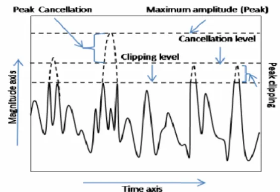
After we determine the pre-distortion function of the non-linear PA we are able to make the overall system linear but this still will not insure that the high power amplifier is not driven in the saturation region. The PA should be avoided to be driven in the saturation region as it also introduces the performance degradation and even burn out the transponder which is very critical in the satellite communication system. The failure of the transponder leads to the failure of the satellite system. We used the ‘partial peak cancellation and clipping’ technique to reduce the PAPR of the signal which is introduced in [8]. Fig.1 depicts the process of ‘partial peak cancellation and clipping’.
In this method we determine the two level of signal one for clipping and another for peak cancellation namely clipping level and cancellation (subtraction) level respectively. The clipping level is determined by setting the appropriate clipping ratio (CR) and the cancellation level is determined as the certain percent (typically 30% to 60%) of the difference
between the maximum amplitude (peak) and the clipping level, add with the clipping level. The OFDM signal with the magnitude greater than the cancellation level is subtracted by constant amplitude. This amplitude is determined as the difference between the maximum amplitude (peak) and the clipping level which is also the reference signal amplitude. The OFDM signal with the magnitude between the clipping level and the cancellation level are clipped at the clipping level.
And those signals with magnitude less than clipping level are left untouched. The reference signal is assumed to be somehow transmitted (using pilot, paging channel etc.)
Fig. 1. Process of partial peak cancellation & clipping
II. OFDM System model
The set of data bits [b b b1 ... 2 3 bM]as an input to the OFDM system is modeled using the QAM (Quadrature Amplitude Modulation) or PSK (Phase Shift Keying) to the baseband symbol.
N such modulated symbols ( (0),X X(1),X(2),... (X N−1)) are packed together at the input of the IFFT block using a serial to parallel converter.
The OFDM signal in the time domain is generated by IFFT operation as shown in (1)
2 ( 1)( 1)/
1
( ) ( ) ( ) 1 ( ) [1,2, ]
N
j k n N
r i
k
x n x n jx n X k e for k N
N
π − −
=
= + =
∑= L
(1)The Cyclic Prefix equal to 25% of the length of OFDM symbol is considered for the guard interval.
Normally N is taken very large, so according to central limit theorem, the amplitude of an OFDM signal has Rayleigh distribution. The PAPR can be obtained by
2 2
| ( ) |
, [1, ] [| ( ) | ]
max x n
PAPR n N
ε x n
= ∈ (2)
Where {}ε ⋅ denotes the expectation.
Finally, we get the analog signal after DAC as,
( ( ))
( ) Re[ ( ) j ct t ]
x t% = x t e ω +φ (3) with the amplitude and phase of the input signal, fed to the HPA for RF transmission.
The high PAPR of OFDM signal requires a very good linear transmission of the signal. Power amplifiers are typically the most power-hungry components of RF transceivers. The design of PAs, especially for linear, low-voltage operations, remains a difficult problem defying an elegant solution.
Two types of PAs are used for communication systems: TWTA in high power satellite communications and SSPA for several other communication systems, especially mobile systems. The complex output of RF with non- linear distortion can be expressed as
{ ( ) ( ( ))}
( ) { ( )} j t t
X t% =Aρ t e ϕ +φ ρ (4) Where ρ( )t and ϕ( )t are amplitude and phase of the input signal. ( )Aρ and φ ρ( ) is AM/AM and AM/PM conversion of the pre- distortion
III. PROPOSED SCHEMES
Although the pre-distortion method proposed in [7] has nearly linear amplified signal in the RF output, however there was divergence from the linearity for pre-distortion when the input increases to a critically high level, thus the output becomes deeply saturated. Also the pre-distortion works in a limited input range without saturation.
They have used the SSPA (Solid State Power Amplifier) model for the HPA. To overcome this problem we slightly change the application of pre- distortion in the system along with the peak reduction technique so as to drive the PA in the linear region enhancing the performance. The peak reduction used here is ‘partial peak cancellation and clipping’ which is introduced in [8]. The results were not verified for the
conventional OFDM system in that paper. Here in this paper we used the method in conjunction with adaptive pre-distorter for the compensation of TWTA non-linear inter-modulation of satellite WiBro.
Even though equation (4) gives us a simple model for analysis, we will use a memory-less polynomial to capture the non-linear characteristics of the transmitter, regardless of the PA type because the inverse of (4) is not easy to solve. The polynomial is written as,
0 1
0 0
( ) ( ) ( ) ( )
P P
i k
i k
i k
y t αx t α αx t α x t
= =
=
∑
= + +∑
(5)Where ( )x t and ( )y t are input and output of the nonlinear amplifier respectively.
a0 represents the DC offset, α1is the linear scalar, {α2,...αp} contribute to non-linearity in the system and P is the highest order of the system.
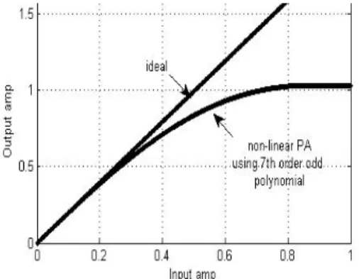
For the sake of simulation, in this paper we used the seventh order odd polynomial for representing the non-linear PA [12], i.e. the coefficients
0, 2, 4
α α α and α6 are set to zero and remaining
1, 3, 5
α α α and α7 were set carefully having positive and negative values alternately. Fig.2.
depicts the input/output curve of the polynomial.
Here we have only considered AM/AM conversion for the simulation.
Fig. 2. AM/AM response of TWTA
Furthermore it will be shown that this model provides several conveniences in estimation and compensation. We used the discrete formulation by assuming that we already get the samples of both ( )x t and ( )y t in (5). The combinational effect of various block in the system causing non- linearity are considered for determining the
polynomial coefficient. As a result the overall non- linearity for cascade non-linear systems
2 1
(... ( ( ))...)
fN f f x was determined, represented as f x( ) .The proposed pre-distorter schemes consist of two stages: the estimation stage and the compensation stage for the actual signal.
1.1 LS estimation of non-linearity
In the estimation stage, we used a training sequence with sufficient dynamic range to probe the non-linearity. The training sequence is carefully chosen to cover the dynamic range of the PA. A feedback of the RF output to the base- band with this sequence is sampled,
0
( ) ( )i
n n
P
i
y f x x t
=
= =
∑
(6)The signal vectors of N×1 are defined,
1 2
[ ... ]T
t N
Y= y y y is the feedback vector of the RF output, Xt=[x x1 2...xN]T is the input training sequence vector and non-linear polynomial coefficient vector andα = α α α[ 0 1 2...αp]T . Now, the above equation (6) can be represented in matrix formulation as,
t t
Y =X ∗ α (7) Where Xt is a Vandermonde matrix of N´ P each element of which is calculated as,
,
1, [1, ], [1, ]
i j j
t i
X =x− i∈ N j∈ P (8) Finally, the Least Square estimation of the non-linear PA can be represented by the polynomial coefficients which can be computed as below,
[ tH t]1 tH t
a&= X X − X ∗Y (9) The term XtH in the above equation denotes the Hermitian of the Vandermonde matrix (X ). t Hermitian is simply the conjugate and transpose of a matrix. Thus the optimal estimation of the non-linearity can be achieved by using the estimated coefficients α
1.2 Pre-distorter
The base band digital signal is fed to the processer for sample-by-sample pre-distortion.
The main objective pre-distortion is to make the overall effect of RF output linear. Here we intend to find such function. Let us suppose a function g(x) to be the another polynomial of order Q such that, it would pre-distort the input signal as,
0
( ) ( ( )) ( )
Q i i i
x n g x n βx n
=
= =
∑
( (10)
So if ( )x n( is passed through the PA the output should be linearly scaled. That is,
1
0 0 0
( ) ( ( )) ( ) ( )
Q P Q
P
j i k
i j k
i j k
y n β x n + γ x n x n
= = =
=
∑ ∑
α =∑
≈ α%
(11) with γkrepresenting both α and i β . i For determining the solution f−1( )y is fitted by another Q order polynomial from training data,
1
0
( ) ( ( )) ( ( )) ( )
Q i
t t t i t
i
x n f− y n l y n λy n
=
= = =
∑
(11)Similarly, we get the solution as, [Y YtH t]−1YtH Xt
∧ =& ∗ (12) with Yt as Vandermonde matrix of the output and YtHas the Hermitian of Y . t λ= [ ] λ λ0 1...λQ is the estimated inverse non-linearity coefficient vector.
Now, form equation (10), (11) & (12) we get the solution of g(x),
1
1
0 0
( ( )) ( ( )) ( ) ( )
Q Q
i i i
i i
i i
g x n f− y n λα x n βx n
= =
= % =
∑
=∑
(13) Therefore, βi =λαi 1i creates the pre- distorter function g(x).
1.3 Partial peak cancellation and clipping In this section we will implement a technique to reduce the PAPR of the OFDM signal. In this technique the transmitter side, position of the high peak from the output amplitude of IFFT block is recorded. The peak cancellation and clipping level is determined by first setting the Clipping Ratio (CR) which is the ratio of the clipping power and the average power.
(clp) avg
Clipping level l = CR P∗ (13) The reference signal is generated and
subtracted from the OFDM signal. The reference signal is somehow transmitted (e.g.: using pilot channel) which contains only the position and amplitude of the peak being subtracted.
( ) ,
0,
n clp
n clp
a r l
ref n
r l
ρ ρ
> +
= ⎨⎧⎪⎪⎩ ≤ + (14)
Where, a=peak−lclip is the difference between the maximum peak and the clipping level; rn= s n( ) , ρ = giving the percentage w α,w of (0α < < . w 1)
Furthermore we use peak cancellation level aslcan= ρ +lclip . Then the output signal after partial peak cancellation and clipping is given by,
, , ,
n n can
ppc can clp n can
n n clp
r a r l
r l l r l
r r l
⎧ − >
=⎪⎨ ≤ ≤
⎪ <
⎩
(15)
Thus obtained signal is then performed with the filtering process to remove possible Out-Of- Band (OOB) radiation.
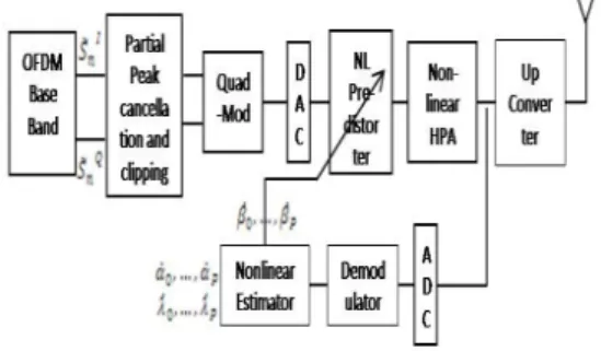
The overall technique architecture block diagram is shown in Fig.3
Fig. 3. Overall baseband compensation
IV. PERFORMANCE RESULT
Here in this section the simulation result for the purposed compensation technique is presented. The number of subcarrier is N=4096, and the modulation technique is QPSK for the OFDM symbol. In the analysis we used the normalized model given by the 7th order odd polynomial
1 1.9817, 3 1.3638, 5 0.4507, 7 0.0524)
α = α = − α = α = −
(
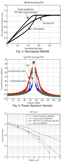
, (these values have been generated using least- square fitting [12]) with the gain of 20dB as shown in Fig.2. This specification is typically for the satellite system with TWTA as a PA. The response of the system with the pre-distortion is shown in the Fig.4. Q=7 is used as the polynomial fitting for generating the pre-distorter. The PA was operated in the 3dB IBO (input back-off). IBO is defined as the input power that delivers maximum output power (Saturation power) over the mean power of the transmitted signal as:
max
( ) 10log10 avg
IBO dB P
= P (16) Where, Pmax is the input power that delivers the maximum power (Saturation Power) and Pavg is the average input power.
For the ‘partial peak cancellation and clipping’, the clipping level (CR) was selected as 4 and w as 0.5. The reference signal is simply the set of pulse signals which have amplitude equal to the difference between the peak of each OFDM symbol and the maximum permissible amplitude where the signal crosses the cancellation threshold. The channel medium was selected as the AWGN channel.
The PSD (Power Spectrum Density) of input signal, uncompensated output signal and compensated output signal is depicted in Fig.5. It is clearly seen in the figure that the out-band radiation is suppressed effectively. The SER (Symbol Error Rate) performance for pre- distortion and ‘partial peak cancellation and clipping’ were computed along with the uncompensated signal using the non-linear PA and the ideal PA. These plots are shown in the Fig.6. In the figure we can see that the SER performance of the pre-distorted signal is much better than the normal nonlinear amplification without pre-distortion. For 0.1% SER the normal OFDM signal (designated as ‘Without pre- distorter’) is around 12dB where as it is nearly 7.5dB for the pre-distorted OFDM signal. The SER curve in the figure approaches towards the ideal curve. The curve further approaches to the ideal curve as the ‘partial peak cancellation &
clipping’ was applied along with the pre-distortion of the OFDM signal.
Fig. 4. Normalized AM/AM
Fig. 5. Power Spectrum Density
Fig. 6. SER Performance
V. CONCLUSION
Polynomial model estimation of both the non- linearity of PA and inverse nonlinearity of TWTA in a satellite WiBro communication system was achieved using the LSE estimation. Thus obtained per-distorter is used along with the partial peak cancellation and clipping. The normal (non- compensated) OFDM signal from the PA is
compared with the purposed compensated signal.
The result was supportive enough to show the success in implementation of the purposed compensation technique.
Acknowledgment
This work was supported by 2005 (Korea Aerospace University) Faculty Research Grant.
References
[1] L. J. Cimini, Jr., “Analysis and simulation of a mobile radio channel using orthogonal frequency division multplexing,” IEEE Trans.
Comm., vol. 33, no. 7, pp. 665–675, July 1985.
[2] Richard van Nee and Ramjee Prasad, “OFDM Wireless Multimedia Communications ,” Artech House Boston London, pp. 119-126, 2000 [3] X. Li and L. J. Cimini Jr.,”Effects of clipping and
filtering on the performance of OFDM,” IEEE Communication Letters, pp. 131-133, May 1998.
[4] Hideki Ochiai and Hideki Imai,” On Clipping for Peak Power Reduction of OFDM Signals”
IEEE Trans, Institute of Industrial Science, The University of Tokyo.
[5] Andreas Saul, “Generalized Active Cons- tellation Extension for Peak Reduction in OFDM Systems,” IEEE Trans, DoCoMo Euro- Labs, pp. 1974-1979, May. 2005
[6] P. Van Eetvelt, G. Wade and M. Tomlinson,”
Peak to average power reduction for OFDM schemes by selective scrambling,” Electronic letters, vol. 32, pp. 1963-1994, Jan 2000.
[7] Yuanbin Guo, Joshep R. Cavallaro, “Enhanced Power Efficiency of Mobile OFDM Radio using Pre-distortion and Post Compensation,” IEEE Trans, ECE Department, Rice University, pp.
214-218, 2002
[8] Lei Wang, Kyong kuk cho, Dong weon Yoon and Sang Kyu Park, “A Recoverable Peak Cancellation Technique for PAPR Reduction of OFDM Signals,” IEEE Trans, Department of Electronics and Computer Engineering, Hanyang University, pp. 1124-1127, June 2006.
[9] Gopi K. Manne and Tim Yao, ”On the
Predistortion Technique for improveing transmission Linearity of OFDM System”, IEEE Trans, Department of Electrical and Computer Engineering, University of Texas. pp. 3876 - 3879, 2004.
[10] Sukhdeep Mahil and Abu B. Sesay, “Rational Function Based Predistorter for Traveling Wave Tube Amplifiers,” IEEE. On broadcasting vol. 51, no.1, pp. 77-83, March. 2005.
[11] Josep Sala – Hugo Durney, “Unconditionlly Convergent pre-Distortion of non-Linear High Power Amplifiers”, Signal Processing group, Department of Signal Theory and Communi- cations, Universitat Politecnica. IEEE pp.
1649-1653, 2001
[12] Tri T. Ha, “Digital Satellite Communication”, Second edition, McGraw-Hill pp.
저 자 Robin Shrestha
2006년 2월 :
National College of Engineering,
Tribhuvan University, Nepal.
2007년 9월 : 한국항공대학교 통신공학과 석사과정
<관심분야> 통신공학
이 병 섭 (Byung-Seub Lee) 1979년 2월 :
한국항공대학교 전자공학과 졸업 1981년 2월 :
서울대학교 전자공학과 석사 1992년 2월 :
New Jersey Institute of Technology 박사 1992년∼현재 : 한국항공대학교
항공전자 및 정보통신공학부 교수
<관심분야> 위성통신,신호처리,adaptive array