Vol. 23, No. 9 (2013)
489
Effect of Nozzle Tip Size on the Fabrication of Nano-Sized Nickel Oxide Powder by Spray Pyrolysis Process
Donghee Kim* and Jaekeun Yu** †
*Department of Anesthesiology, Dankook University, Cheonan 330-714, Korea
**Department of Advanced Materials Engineering, Hoseo University, Asan 336-795, Korea (Received August 7, 2013 : Received in revised form August 21, 2013 : Accepted August 26, 2013)
Abstract
In this study, by using nickel chloride solution as a raw material, a nano-sized nickel oxide powder with an average particle size below 50 nm was produced by spray pyrolysis reaction. A spray pyrolysis system was specially designed and built for this study. The influence of nozzle tip size on the properties of the produced powder was examined. When the nozzle tip size was 1 mm, the particle size distribution was more uniform than when other nozzle tip sizes were used and the average particle size of the powder was about 15 nm. When the nozzle tip size increases to 2 mm, the average particle size increases to roughly 20 nm, and the particle size distribution becomes more uneven. When the tip size increases to 3 mm, particles with an average size of 25 nm and equal to or less than 10 nm coexist and the particle size distribution becomes much more uneven.When the tip size increases to 5 mm, large particles with average size of 50 nm partially exist, mostly consisting of minute particles with average sizes in the range of 15~25 nm. When the tip size increases from 1 mm to 2 mm, the XRD peak intensities greatly increase while the specific surface area decreases. When the tip size increases to 3 mm, the XRD peak intensities decrease while the specific surface area increases. When the tip size increases to 5 mm, the XRD peak intensities increase again while the specific surface area decreases.
Key words
nickel chloride solution, spray pyrolysis process, nano-sized nickel oxide powder, average particle size, nozzle tip size.1. Introduction
Spray pyrolysis process
1-11)was one of the methods of manufacturing nano-sized metal oxide powder. In this re- action, chemical components are uniformly blended in the solution state so as to make a complex solution, which was in turn sprayed into a reaction furnace with a high temperature. In the furnace, spray pyrolysis reaction was accomplished instantly, and as a result, the ultra-fine metal oxide powder was formed. The advantages of this method include the following: 1) processes such as the mixing, calcination, and milling of solid powder can be omitted, which therefore makes the whole process rela- tively simple; 2) mixing with impurities can be reduced, and the properties of the generated particles can be con- trolled according to the different conditions of the pyrol- ysis reaction.
Presently, several manufactories, such as Scimarec of
Japan, Merck of German, and SSC of USA, are pro- ducing highly functional ceramic powders manufactured using the spray pyrolysis method. Meanwhile, research activities related to the spray pyrolysis method are being conducted by Yu,
1-7)Majumdar,
8)Pluym,
9)Elmasry
10)and Messing,
11)and the applications of this method are ex- panding quickly. For examples, in steelmakings, this method was used to manufacture iron oxide powder from the waste acid solution produced in the process of rinsing the surface of hot rolled steel sheets with hydrochloric acid solution. Also, tin oxide powder with the average particle size below 50 nm was manufactured from tin chloride solution,
1)ITO powder with the average particle size below 50 nm was manufactured from wase ITO target,
5)and Ni-ferrite powder with the average particle size below 100 nm was manufactured from the waste solution gener- ated in the shadow mask manufacturing process.
7)How- ever, spray pyrolysis method has not been applied for the
†
Corresponding author
E-Mail : [email protected] (J. K. Yu, Hoseo Univ.)
© Materials Research Society of Korea, All rights reserved.
This is an Open-Access article distributed under the terms of the Creative Commons Attribution Non-Commercial License (http://creative-
commons.org/licenses/by-nc/3.0) which permits unrestricted non-commercial use, distribution, and reproduction in any medium, provided the
original work is properly cited.
490 Donghee Kim and Jaekeun Yu
manufactures of nano-sized nickel oxide powder, while its applications for the catalysis, removal of the dye, semi- conductor materials and magnetic materials are expanding rapidly.
In this study, a chloride solution that contains nickel component was used as the raw material of the spray pyrolysis process to produce a nickel oxide powder with an average particle size below 50 nm. This study was also intended for determining the effect of the nozzle tip size on the properties of the produced powder.
2. Experimental
In this study, a nickel oxide powder with average parti- cle size below 50 nm was manufactured from the nickel chloride solution with the presence of nickel ions by using spray pyrolysis process. First, NiCl
2.6H
2O with purity above 99 % made by Aldrich company was dissolved into the ultra high purity water. And, this raw material solution was diluted by distilled water so that the nickel concentration in the solution was adjusted 100 g/L.
In order to produce the nano-sized nickel oxide powder with average particle size below 50 nm, a spray pyrolysis system was specially designed and built for this study.
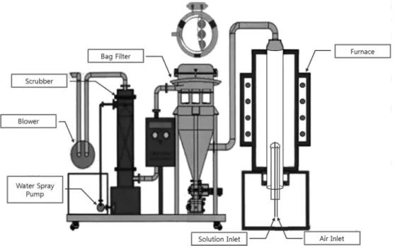
The schematic diagram of this system was shown in Fig.
1. This system enables the following features: the raw material solution can be sprayed into the reaction furnace after being efficiently atomized, the produced powder can be collected effectively by a powder collection device named bag filter, and the toxic gases generated in the process can also be cleansed by a scrubber.
In this study, the raw material solution was atomized
into ultra fine droplets through a nozzle made of titanium, and the inside diameter of the nozzle tip was varied at 1, 2, 3 and 5 mm. And the solution was turn sprayed into a reaction furnace with the inside temperature maintained at 800
oC. Subsequently, nickel oxide powder with the average particle size below 50 nm was produced, and was collected by a bag filter. The raw material solution was fed into an inlet of the nozzle by a micro pump with the inflow speed adjustable to 10 ml/min, while the pre- ssurized air supplied by an air compressor was fed into the other inlet of the nozzle with pressure of 3 kg/cm
2so that the solution can be micronized. The properties of the produced powder were examined by TEM(JEM-2100F, JEOL Ltd.) analysis(whether the production of single crystal particles), SEM(Quanta 200, FEI Ltd.) analysis (particle size distribution and particle shape), XRD(D/
Max-2500V, Rigaku Ltd.) analysis(powder phase and com- position), and the measurement of specific surface area (ASAP 2020, micromeritics Ltd.).
3. Results and Discussion
Fig. 2 was the 30,000 times magnified image of the generated powder under SEM, which shows the pro- perties of the generated powder relative to the size of the nozzle tip from 1 mm to 5 mm, given that the reaction temperature was kept at 800
oC, nickel concentration of the raw material solution at 100 g/L, air pressure at 3 kg/
cm
2and the inflow speed of solution at 10 ml/min. As the tip size increases from 1 mm to 2 mm, the average particle size of the powder increases while the particle size distribution becomes more uneven.
Fig. 1. Schematic diagram of spray pyrolysis system.
The law material solution was atomized by the nozzle, forming a droplet, and the droplets are flowed inside the reactor followed by the pyrolysis reaction process. During this process, because a solute of the NiCl
2was produced by solidifying from the surface of the droplet, if the solvent existing inside the droplet cannot easily pass through the surface of the solid layer, the internal pressure of the droplet rises and ultimately the droplet will burst.
When the tip size was 1 mm, the atomized droplet size was small and the burst of the droplet decreases, there- fore the particle size distribution of the powder formed was more uniform and compact structured compared to other tip sizes. As shown in Fig. 2(a), the average parti- cle size was roughly 15 nm of ultra-fine form. On the other hand, the shape of the formed particles was mostly of sphere shape. When the nozzle tip size increases to 2 mm, the droplet size dramatically increases to when the nozzle tip size was 1 mm, therefore as the pyrolysis reaction proceeds, the internal pressures of the droplets increase, leading to a severe burst of the droplets, making the particle size distribution of the particles more uneven.
On the other hand, as shown in Fig. 2(b), the average particle size of the particles increases to about 20 nm This result was mainly because that the complex effect of the increase in the droplet size and evaporation heat of the solvent as the increase in tip size was more predominant than the increase effect of the burst of the droplets due to the increase of the tip size. When the tip size increases to 3 mm, the droplet size increases further, therefore as the pyrolysis reaction proceeds, droplets burst more severely and the particle size distribution becomes more uneven.
As shown in Fig. 2(c), the particles coexist with relative
large particles of sized 25 nm and particles of equal or
less than 10 nm of ultra-fine particles. This result was
mainly because that the increase effect of the droplet size
as the increase of the tip size and decrease effect in the
burst of the droplets due to the increase in the evaporation
heat of the solvent lead to quite a number of particles
with larger size than the case of 1 mm or 2 mm tip and
the dramatic increase of the burst of the droplets due to
an increase in the tip size also lead to quite a number of
particles of average particle size equal to or less than
Fig. 2. SEM photographs of produced powder according to nozzle tip size at reaction temperature of 800
oC, raw material solution of 100
g/L, air pressure of 3 kg/cm
2and inflow speed of the solution of 10 ml/min. (a) 1 mm, (b) 2 mm, (c) 3 mm, (d) 5 mm.
492 Donghee Kim and Jaekeun Yu
10 nm size. When the tip size increase to 5 mm, the drop- let size increases further, therefore during the pyrolysis process, more severely burst of the droplets makes a more uneven particle size distribution. As shown in Fig.
2(d), large size particles of size 50 nm partially exists and most of the particles consist of minute particles of size 15~25 nm. This was mainly because, as the tip size largely increases to 5 mm, the droplet size also increases significantly, and despite the severe burst of the droplet, particles of average size 50 nm partially exist. On the other hand, as the tip size increases dramatically to 5 mm, the burst of the droplets was more severe than the reaction conditions of any other tip size, however, be- cause of the increase in the evaporation heat of the solvent due to the increase in droplet size, it simultane- ously has a decreasing effect on the burst of the droplet, thereby making the average size of the particles formed roughly 15~25 nm.
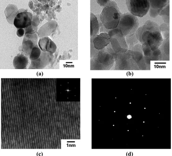
Fig. 3 shows the micro-structural characteristics of the particles formed during the pyrolysis process by using a
TEM. The particles in Fig. 3(a), (b) and (c) are expanded by 300,000 times, 300,000 times and 7,000,000 times respectively to confirm whether or not it was primarily a single crystal. Furthermore, a FFT(Fast Fourier Transform) pattern and diffraction pattern was shown in arbitrary particles of (c) and (d) in Fig. 3. Similar patterns are shown in other particles and it was confirmed that the particles formed from these results forms a close single crystal structure.
Fig. 4, the results of XRD analysis under the same re- action conditions as in Fig. 2, shows the chemical forms of the generated powder under each nozzle tip size and the corresponding Miller Indexes of each peak. Regard- less of the changes in tip size from 1 mm to 5 mm, NiO was the only existing form of the powder, and that the corresponding Miller Indexes of individual peaks main- tain at a fixed level. When the tip size increases from 1 mm. to 2 mm, not only the intensity of the main peak shown in the Miller index (012), but the intensities of the second and third peak of (101) and (110) respectively
Fig. 3. TEM photographs of produced powder and selective diffraction pattern of single particle at reaction temperature of 800
oC, raw
material solution of 100 g/L, air pressure of 3 kg/cm
2, inflow speed of the solution of 10 ml/min. and nozzle tip size of 2 mm. (a) TEM
photographs of produced powder( × 300,000), (b) TEM photographs of produced powder(× 300,000), (c) HRTEM image of an individual
NiO nanocrystal. The insert shows the corresponding FFT pattern, (d) Selective diffraction pattern of single particle.
increase significantly. This result was mainly because that as shown in Fig. 2, the average particle size was about 15 nm when the tip size was 1 mm, whereas the average particle size increases dramatically to 25 nm when the tip size was 2 mm. When the tip size increases to 3 mm, not only the intensity of the main peak shown in the Miller index (012) but also the intensities of the second and third peak in (101) and (110) respectively decrease, and shows a similar value when the tip was 1 mm. This was mainly because that as the tip size increases to 3 mm, the increase of the droplet size makes relatively large size particles with average size 25 nm, however the dramatic increase of the burst of the droplets due to an increase in the tip size also lead to quite a number of particles of size equal to or less than 10 nm size. When the tip size increases to 5mm, not only the intensity of the main peak shown in the Miller index (012), but the intensities of the second and third peak of (101) and (110) respectively increase significantly again. This was mainly because as the tip size increases dramatically to 5 mm, most of the particles show an average particle size of 15~25 nm due to the increase effect of the burst of the droplet, however, large size particles with size 50 nm also partially exist because of the increase of the droplet size due to the increases in tip size.
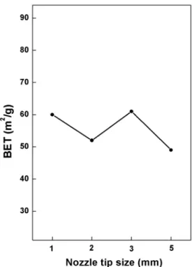
Fig. 5 was the changes in specific surface area of the powder as the tip size increases under the same reaction
conditions as in Fig. 2. As the tip size increases from 1 mm to 2 mm, the specific surface area of the particles decreases. As shown in Fig. 2, this result was mainly because the average particle size was about 15 nm when the tip size was 1 mm, whereas the average particle size increases to about 20 nm when the tip size was 2 mm.
When the tip size increases to 3 mm, the specific surface area of the particles increases again, showing a similar value to when the tip size was 1mm. This was mainly because as shown in Fig. 2(c), particles of average size 25 nm also exist alongside ultra-fine particles of average size equal to or less than 10 nm. When the tip size in- creases to 5 mm, the specific surface area of the particles decreases again. As shown in Fig. 2(d), this result was mainly because when the tip size was 5 mm, particles are mostly average size of 15~25 nm and coexist with some particles with average size 50 nm, therefore the average particle size increases compare to when the tip size was 3 mm. When the tip size was 5 mm, the XRD peak intensities are relatively dramatically increases but the specific surface area was only slightly decrease com- pared to when the tip size was 3 mm. This result was mainly because that the increase of the evaporation heat of the solvent during the pyrolysis process due to the increase of the tip size makes the less compact structure of the particles, thereby the increase effect of the specific surface area occurs.
Fig. 5. Specific surface areas of powder according to nozzle tip size at reaction temperature of 800
oC, raw material solution of 100 g/L, air pressure of 3 kg/cm
2and inflow speed of the solution of 10 ml/
min.
Fig. 4. XRD patterns of produced powder according to nozzle tip
size at reaction temperature of 800
oC, raw material solution of
100 g/L, air pressure of 3 kg/cm
2and inflow speed of the solution
of 10 ml/min. (a) 1 mm, (b) 2 mm, (c) 3 mm, (d) 5 mm.
494 Donghee Kim and Jaekeun Yu
4. Conclusions
This research uses nickel chloride solution as a raw material to produce the nickel oxide powder of average size equal to or less than 50 nm by the spray pyrolysis process. And, a spray pyrolysis system was specially de- signed and built for this study.
The influence of nozzle tip size on the properties of the produced powder was examined.
When the nozzle tip size was 1 mm, the particle size distribution was more uniform than the cases of other tip size and the average particle size of the powder was about 15 nm. When the nozzle tip size increases to 2 mm, the average particle size increases to roughly 20 nm, and the particle size distribution becomes more uneven.
When the nozzle tip size increases to 3 mm, the particles with average size of 25 nm and equal to or less than 10 nm coexist and the particle size distribution becomes much more uneven. When the nozzle tip size increases to 5 mm, large particles with average size of 50 nm partially exist, mostly consisting of minute particles of average size 15 25 nm. Regardless of the changes in tip size from 1 mm to 5 mm, NiO was the only existing form of the generated powder. When the nozzle tip size increases from 1 mm to 2 mm, the XRD peak intensities increase while the specific surface area decreases. When the nozzle tip size increases to 3 mm, the XRD peak intensities decrease while the specific surface area increases. When the nozzle
tip size increases to 5 mm, the XRD peak intensities increase again while the specific surface area decreases.
References
1. J. K. Yu and D. H. Kim, Kor. J. Mater. Res., 23(2), 81 (2013).
2. J. K. Yu and D. H. Kim, Powder Tech., 235(2), 1030 (2013).
3. J. K. Yu and D. H. Kim, J. of Nanosci. Nanotechnol., 12(2), 1545 (2012).
4. J. K. Yu and D. H. Kim, J. Ceram. Soc. Jpn., 117(10), 1078 (2009).
5. J. K. Yu, S. G. Kang, K. C. Chung. J.S. Han and D.H.
Kim, Mater. Trans., 48(2), 249 (2007).
6. J. K. Yu, S. G. Kang, J. B. Kim, J. Y. Kim, J. S. Han, J. W. Yoo, S. W. Lee and Z. S. Ahn, Mater. Trans., 47(7), 1838 (2006).
7. J. K. Yu, K. W. Kim, T.S . Kim and J. Y. Kim, Mater.
Trans., 46(7),1695 (2005).
8. D. Majumdar, T. A. Shefelbine and T. T. Kodas, J. Mater.
Res., 11(11), 2861 (1996).
9. T. C. Pluym and T. T. Kodas, J. Mater. Res., 10(7), 1661 (1995).
10. M. A. A. Elmasry, A. Gaber and E. M. H. Khater, Powder Tech., 90(1),165 (1997).
11. G. L. Messing, S. C. Zhang and G. V. Jayanthi, J. Am.
Ceram. Soc,. 76(11), 2707 (1993).