C o p y r ig h t 2 0 0 5 K S A E 1 2 2 5 - 6 3 8 2 / 2 0 0 5 / 0 7 4 - 0 8 T r a ns a c tio ns o f K SA E , V o l. 1 3 , N o . 2 , p p .5 2 -5 7 (2 0 0 5 )
1 . 1 )
.
*T o w h o m c o rr e s p o n d e n c e s h o u ld b e a d d re s s e d . h a n y c @ k o o k m in .a c .k r
,
N O x P M .
P M
P M
K IV A -3 V C F D -A C E +
P M
* 1 ) 2 ) 3 ) 3 )
1) 2) 3)
A Study on Prediction of Flow Characteristics and Performance of a Heavy-Duty Diesel Engine
with Continuously Regenerating Method PM Reduction
Youngchool Han*1) Byungchul Moon2) Sangki Oh3) Doosung Baik3)
1)The Department of Mechanical Engineering, Kookmin University, Seoul 136-702, Korea
2)Seoul-Jeongsu Polytechnic College Car-Electronics, Seoul 140-823, Korea
3)Graduate School of Automotive Engineering, Kookmin University, Seoul 136-702, Korea (Received 3 August 2004 / Accepted 25 November 2004)
A b s trac t : T h e in c re a s in g a u to m o b ile s c o n tin u e to c a u s e a ir-p o llu tio n p ro b le m s w o rs e th a n e v e r. In fa c t, m a n y a u to m o b ile re s e a rc h a re in v o lv e d in h o w to re d u c e e x h a u s t e m is s io n s e ffe c tiv e ly s p e c ia lly in N O x a n d P M to c o m p ly w ith s trin g e n t e m is s io n s ta n d a rd s , E u ro V . T h is re s e a rc h e m p h a s iz e d o n th e d e v e lo p m e n t o f c o n tin u o u s re g e n e ra tio n D P F te c h n o lo g y w h ic h w a s o n e o f p ro m is in g re m o v in g te c h n o lo g y o f p a rtic u la te m a tte rs b e c a u s e o f its c o m p a ra b ility a n d h ig h a p p lic a b ility . In a d d itio n , th is re s e a rc h d is c u s s e d o n s o m e d e s ig n p o in ts o f v ie w th ro u g h c o rre la tio n s tu d y b y c o m p a rin g th e e x p e rim e n ta l d a ta w ith c o m p u ta tio n a l re s u lts b y th e in tro d u c tio n o f c o m m e rc ia l c o d e s s u c h a s C F D -A C E + a n d K IV A -3 V . T h e n u m e ric a l s im u la tio n o n th e p e rfo rm a n c e o f c o n tin u o u s re g e n e ra tio n D P F a p p a ra tu s a n d c o rre s p o n d in g e m is s io n c h a ra c te ris tic s h a s b e e n p re d ic te d w e ll e n o u g h a n d v e rifie d w ith e x p e rim e n ta l re s u lts . T h e p re s s u re a n d a v e ra g e te m p e ra tu re s a re d e c re a s e d to a b o u t 2 .6 % a n d 1 .4 % re s p e c tiv e ly u n d e r a fu ll e n g in e lo a d c o n d itio n m a in ly d u e to b a c k p re s s u re s ra is e d b y d ie s e l p a rtic u la te filte r. P re s s u re , te m p e ra tu re a n d h e a t re le a s in g ra te s te n d to d e c re a s e s p e c ia lly a t h ig h e r e n g in e lo a d , b u t th e y a re n o t a ffe c te d a t lo w e r e n g in e lo a d re g io n s .
K e y w o rd s : A ir-p o llu tio n ( ), N O x ( ), P M ( ), D P F ( )
P M
P M .
2 .
2 .1
K IV A -3 V
C F D -A C E + P M
. K IV A -3 V
,1 )
.2 ) T a b le 1 F ig . 1
.
Table 1 Mathematical model for physical phenomena of KIVA-3V
P h y s ic a l p ro c e s s S u b m o d e l S p ra y S ta n d a rd s p ra y m o d e l D ro p d ra g D ro p le t d ra g a n d d is to rtio n m o d e l D ro p le t b re a k u p W a v e m o d e l
A to m iz a tio n T A B m o d e l
W a ll im p in g e m e n t W a tk in s -P a rk m o d e l
C o m b u s tio n
H y b rid m o d e l
L a m in a r fla m e A rrh e n iu s m o d e l D iffu s io n fla m e E d d y b re a k u p m o d e l
E m is s io n
N O x E x te n d e d Z e ld o 'v ic h
S o o t
F o rm a tio n H iro y a s u m o d e l E x tin c tio n N a g le -S tric k la n d
m o d e l
Fig. 1 Configuration of KIVA-3V
P M
C F D -A C E + . C F D -A C E + T a b le 2 .3 )
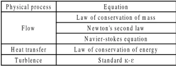
Table 2 Equation for physical phenomena of CFD-ACE P h y s ic a l p ro c e s s E q u a tio n
F lo w
L a w o f c o n s e rv a tio n o f m a s s N e w to n 's s e c o n d la w N a v ie r-s to k e s e q u a tio n H e a t tra n s fe r L a w o f c o n s e rv a tio n o f e n e rg y
T u rb le n c e S ta n d a rd D-?
2 .2
P M
(IV C )
B T D C 1 1 ° . T a b le 3
T a b le 4 .
Table 3 Engine operation condition for analysis
Ite m s S p e c ific a tio n s
E n g in e s p e e d 1 0 0 0 2 2 0 0 (rp m ) S ta rt o f in je c tio n -1 1 (d e g A T D C )
In je c tio n m o d e V e lo c ity ta b le S p ra y a n g le 2 0 .9 7 (d e g )
S w irl ra tio 2 .1 5
C y lin d e r w a ll, p is to n , h e a d te m p . 4 5 0 (K ) In itia l d ro p le t te m p . 3 1 3 (K )
Table 3 Engine specification
Ite m s S p e c ific a tio n s
B o re 1 1 .1 (c m )
S tro k e 1 3 .9 (c m )
S q u is h 0 .2 0 5 (c m )
C o n n e c tin g ro d le n g th 2 4 .6 6 (c m ) D is p la c e m e n t 8 ,0 7 1 (c c )
C o m p re s s io n ra tio 1 7 .2
V a lv e o p e n / c lo s e
In ta k e v a lv e o p e n B T D C 1 6 (d e g ) In ta k e v a lv e c lo s e A B D C 3 6 (d e g ) E x h a u s t v a lv e o p e n B B D C 4 6 (d e g ) E x h a u s t v a lv e c lo s e A T D C 1 4 (d e g )
In je c tio n s y s te m In -lin e
In je c to r n o z z le d ia m e te r 0 .0 1 4 5 (c m )
B o w l ty p e T o ro id a l
Y o u n g c h o o l H an B y u n g c h u l M o o n S an g k i O h D o o s u n g B aik
(IV C )
(E V O ) ,
D o d e c a n e (C1 2H2 6) .
T o ro id a l ,
P M 1 0 0 0 rp m
1 4 0 0 rp m P M
(L o a d ) .
1 0 0 0 2 2 0 0 rp m ,
, 2 5 0 0 0 .
(K 3 p re P ) ,
F ig . 2 .
(a) At crank angle -146°ATDC (b) At crank angle -146°ATDC
(c) At crank angle -146°ATDC (d) At crank angle 146°ATDC Fig. 2 ALE mesh for diesel combustion chamber
IV C
3 4 4 K ,
(S w irl flo w ) . B e s s e l
,
(S w irl ra tio ) .
.
J
,
,
. ,
B e s s e l .
.4 )
?
,
.
7 7 .5 .
A T D C -1 1 ° (S p ra y a n g le )
R e itz .5 )
4 5 0 K ,
. .
. , P M
,
6 5 3 .1 5±K , 3500Pa C F D -A C E + .
A S tu d y o n P re d ic tio n o f F lo w C h arac te ris tic s an d P e rf o rm an c e o f a H e av y - D u ty D ie s e l E n g in e
3 . 3 .1
,
E B U (E d d y B re a k u p M o d e l) . F ig . 3
¤Î 3 × 1 0 1 1
, E B U A 2 0
, .
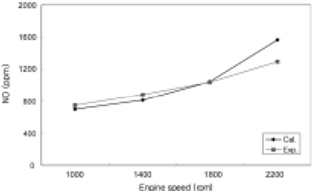
F ig . 4 1 0 0 % N O
. P M
.
1 4 0 0 rp m .
Fig. 3 The effect of model constant K1 and A on a combustion characteristics
Fig. 4 mission prediction compared with experimental results
3 .2
3 .2 .1
F ig . 5 B T D C 1 1 °
.
.
(S w irl) .
Fig. 5 Velocity vector field at BTDC 11°, 2200rpm (Top view and x-z direction view)
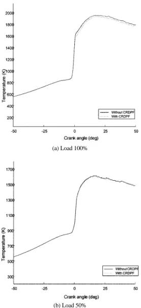
3 .2 .2 F ig . 6
. ,
4 % .
, 5 0 % .
(a) Load 100%
(b) Load 50%
Fig. 6 The effect of CR-DPF on bulk temperature
3 .2 .3 P M
F i g . 7 8 P M
. K IV A -3 V
6 5 3 .1 5±K , 3 5 00 P a
, 0 .3 m /s . J o h n s o n M a tth e y C o .6 ) D O C
N O2 C R -D P F P M
3 5 0 °C
.7 ) J o h n s o n M a tth e y C o . C R - D P F
Fig. 7 Profile of CR-DPF temperature
Fig. 8 Profile of CR-DPF pressure
.
4 .
P M P M
P M
.
1 ) P M
,
.
2 ) P M
4 % .
.
3 ) P M
3 5 0
.
4 ) , C R -D P F
D O C D O C
.
2 0 0 4 B K 2 1
.
R e fe re nc e s
1 ) H . S . K im , “ M o d e lin g o f L iq u id D r o p le t A to m iz a tio n a n d S p r a y W a ll I m p in g e m e n t o f D ie s e l S p r a y s ,” J o u r n a l o f K S M E , V o l.2 3 , N o .1 , p p .6 9 - 8 1 , 1 9 9 9 .
2 ) A . A . A m s d e n , P . J . O 'R o u k e , T . D . B u lte r ,
“ K I V A -ó: A C o m p u ter P ro g ram fo r C h em i- c a lly R e a c tiv e F lo w s w ith S p r a y s ,” L o s A la m o s N a tio n a l L a b o r a to r y R e p o r t L A - 1 1 5 6 0 - M A ( M A y ) , 1 9 8 9 .
3 ) C F D - A C E M a n u a l V e r s io n 6 .4 , C F D R e s e a r c h C o r p o r a tio n , 1 9 9 8 .
4 ) R . D . R e itz a n d R . D iw a k a r , “ S tr u c tu r e o f H ig h - P r e s s u r e F u e l S p r a y ,” S A E 8 7 0 5 9 8 , 1 9 8 7 . 5 ) K . M e in tje s , “ H id d e n - L in e R e m o v a l f o r V ie w - in g T h r e e - D im e n s io n a l S u r f a c e s a n d O b je c ts ,”
G e n e r a l M o to r s R e s e a r c h L a b o r a to r ie s , R e s e - a r c h P u b lic a tio n G M R - 5 3 4 3 , 1 9 8 8 .
6 ) C . A . M a lo n e y , “ S u lp h a te P r o d u c tio n O v e r T h e C R T :W h a t F u e l S u lf u r L e v e l I s R e q u ir e d T o E n a b le T h e E U 4 a n d E U 5 P M S ta n d a r d T o B e M e t? ,” S A E 2 0 0 0 - 0 1 - 1 8 7 5 , 2 0 0 0 .
7 ) B . C . C h o i, J . W . J e o n g , “ S ta te o f th e A r t o f th e A d v a n c e d A f te r - tr e a tm e n t T e c h n o lo g y f o r Z e r o E m is s io n G a s o lin e V e h ic le s ,” J o u r n a l o f K S A E , V o l.2 4 , N o .1 , p .2 0 , 2 0 0 2 .