J Korea Industr Inf Syst Res Volume 18 Number 1 http://dx.doi.org/10.9723/jksiis.2013.18.1.011
Design of a Multiple Band-notched Wideband Circular Slot Antenna
with Arc-shaped Slots
†Junho Yeo* and Cheol-Young Park**
Abstract A design method to achieve multiple band-rejection characteristics in a wideband circular slot antenna is presented. First, a wideband circular slot antenna fed by a coplanar waveguide is designed to operate in the frequency range between 2.3 and 11GHz, which covers WLAN, WiBro, WiMAX, and UWB frequency bands. Next, resonant frequency variations of rejection bands are examined with respect to different slot locations and lengths when slots are inserted on the ground conductor and the circular patch of the antenna. When arc-shaped slots are placed close to the circular transition from a feeding part, multiple notch bands are obtained. In this case, a half of the guided wavelength of the first notch band corresponds to the slot length and other notch bands are integer-multiple of the first band.
Single notch band can be obtained when the slot is located off the transition part. Based on this study, a wideband circular slot antenna with five band-rejection frequency bands at 2.45, 3.5, 4.9, 7.35, and 9.8GHz is designed and fabricated. The first arc-shaped slots are located in the ground conductor close to the circular transition from a feeding part to generate notch bands at 2.45, 4.9, 7.35, and 9.8GHz, while the second slot for 3.73 GHz is placed on top side in the circular patch. The proposed design method is validated by good agreement between the simulated and measured results.
Key Words : wideband circular slot antenna, multiple band rejection, arc-shaped slots
1. Introduction†
In recent years, rapid growth and continuous expansion of wireless communication services have led to a considerably high demand for wideband antennas to support high data transmission with wide bandwidth for multimedia data[1-5]. Among various wideband antennas, printed slot antennas with different shapes of slots and stubs have been
†This research was supported by the Daegu University Research Grant, 2010.
* School of Computer and Communication Engineering, Daegu University, First Author
** School of Electronics Engineering, Daegu University, Corresponding Author(e-mail: [email protected])
widely used[6-8]. There exist many wireless services such as wireless local areas network which might interfere with the wideband system. To prevent such interference, wideband antennas with band-notch function have been introduced by applying the different types of slots[9-11]. In this case, the length of the slot is usually about a half-wavelength at the desired notched frequency and one slot provides single notch band. Therefore, multiple slots need to be inserted to achieve multiple notch bands and the number of slots usually corresponds to that of notch bands.
In this paper, a design method to obtain multiple band-rejection characteristics in a wideband circular slot antenna is proposed. A wideband circular slot
antenna fed by a coplanar waveguide is first designed to operate in the frequency range between 2.3 and 11 GHz. Two different locations of slots for notch bands are considered: one is close to the circular transition from a feeding part and the other is off the transition part. The resonant frequency variations of notch bands are compared for different slot locations and lengths when slots are inserted on the ground conductor and the circular patch of the antenna. All the simulation results are obtained by using commercial EM software Ansoft HFSS[12].
2. Antenna Structure and Design
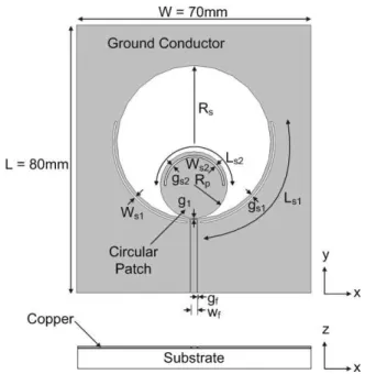
Figure 1 shows the geometry of a coplanar waveguide (CPW)-fed wideband slot antenna with two types of arc-shaped slots. The wideband circular slot antenna consists of a ground conductor, a circular slot, and an inner circular patch. The first arc-shaped slots are located in the ground conductor close to the circular transition from a feeding part, and the second slot is placed on the top side in the circular patch. The dimension of the ground conductor is 70mm by 80mm and the antenna is printed on Tarconic RF-35 board with dielectric constant of 3.5 and thickness of 0.508mm (loss tangent=0.0018). Note that Tarconic RF-35 board is chosen for low loss tangent. The radii of the circular slot and the circular patch are and
respectively, and an offset between the lowest border of the circular slot and the lowest border of the circular patch is .
The inner conductor width and the slot width of a 50 Ohm CPW feed line are assigned as and
, respectively. The length and width of the first arc-shaped slots are and , respectively, and the offset between the circular slot and the first slots is . For the second slot, the length and width are and , respectively, and the offset
between the circular slot and the second slot is .
<Figure 1> Geometry of wideband circular slot antenna with arc-shaped slots.
The design parameters of the wideband circular slot antenna are optimized to achieve a desired operating frequency range of 2.3 to 11GHz. Next, the dimensions of the first and the second arc-shaped slots are optimized to obtain notch bands at 2.45, 3.5, 4.9, 7.35, and 9.8GHz. Table 1 shows the final optimized design parameters.
parameter length(mm) parameter length(mm)
W 70 Ls1 41.9
L 80 Ws1 0.5
Rs 23 gs1 1
Rp 10 Ls2 29
g1 0.25 Ws2 0.5
gf 0.15 gs2 1
wf 1.88
<Table 1> Optimized design parameters of wideband circular slot antenna with arc-shaped slots.
We first investigate the characteristics of notch bands when arc-shaped slots are inserted close to the circular transition from a feeding part. The
possible slot location for this case is either in the ground conductor or in the circular patch. In Figure 2, the input reflection coefficient characteristics of the antenna with arc-shaped slots in the ground conductor near the CPW feed line for
=37.7mm and 41.9mm are compared with the original circular slot antenna without the slots. The location of the slots is shown as in Figure 1 Note that two arc-shaped slots are inserted symmetrically to the CPW feed line to build symmetric radiation patterns.
<Figure 2> Input reflection coefficient characteristics of antenna with arc-shaped slots in ground conductor near CPW feed line.
It is observed that multiple notch bands are obtained where a half of the guided wavelength of the first notch band corresponds to the slot length and the remaining notch bands are integer-multiple of the first band. For instance, four notch bands are generated at 2.45, 4.9, 7.35 and 9.8 GHz in the frequency range of 2.3 to 11GHz when
. For this type of notch bands, the resonant frequency of the integer-multiple notch bands can be expressed in terms of the arc-shaped slot length as
(1)
where is the ith notch frequency of the integer-multiple notch bands, c is the speed of light, and is the effective dielectric constant. In addition, we also see from Figure 2 that the notch bands moves toward high frequency with decreasing slot length and these bands can be adjusted by varying the slot length. In fact, the reason for generating multiple notch bands can be explained by the gradual and smooth transition from the CPW feed line to the circular slot. It provides almost constant input impedance over very wide bandwidth and this creates integer-multiple rejection bands.
Therefore, the slot should be placed near the feeding part to acquire integer-multiple notch bands.
Next, the notch band characteristics of the antenna with arc-shaped slots in the circular patch near the CPW feed line are studied because this position is also close to the circular transition similar to the ground conductor case. Figure 3 shows the geometry of the circular slot antenna with the arc-shaped slots located in the circular patch near the CPW feed line.
<Figure 3> Geometry of antenna with arc-shaped slots located in circular patch near CPW feed line.
The input reflection coefficient characteristics of the antenna with are shown in Figure 4. We observe that two notch bands at 4.98 and 9.95GHz occur in the frequency range of 2.3 to 11GHz. In addition, the multiple notch bands are seen to shift toward high frequency because the slot length is reduced almost half compared to that in the ground conductor.
<Figure 4> Input reflection coefficient characteristics of antenna with arc-shaped slots in circular patch near CPW feed line.
Secondly, the variation of notch bands when an arc-shaped slot is inserted on the top side of the circular patch, which is a case of off the transition part, is investigated. We note that this type of slot is commonly used to generate single notch band in the literature. Figure 5 presents the input reflection coefficient characteristics of the antenna when
and 29mm. In this case, single notch band is only generated and the slot length is close to a half of the guided wave length in the center frequency of the notch band. Similar to the previous case, the notch bands move toward high frequency with decreasing slot length and these bands can be adjusted by varying the slot length. For this case, the resonant frequency of the notch band can be given in terms of the arc-shaped slot length as
(2)
where is the resonant frequency of the notch bands.
<Figure 5> Input reflection coefficient characteristics of antenna with arc-shaped slot on top side of circular patch.
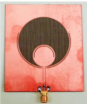
3. Experimental Results and Discussion Based on the results obtained in the previous section, a wideband circular slot antenna with five band-rejection frequency bands at 2.45, 3.5, 4.9, 7.35, and 9.8GHz is designed and fabricated as shown in Figure 6. To generate notch bands at 2.45, 4.9, 7.35, and 9.8GHz, the first arc-shaped slots are located in the ground conductor close to the circular transition from a feeding part. The second slot is placed on the top side in the circular patch to make a notch band at 3.5GHz. The simulated and measured input reflection coefficient characteristics of the fabricated antenna are presented in Figure 7. A good agreement is observed between the simulated and the measured results. The simulated resonant frequencies of the five notch bands are 2.45, 3.5, 4.95, 7.4, and 9.95 GHz, while their measured counterparts occur at 2.45, 3.53, 4.94, 7.37, and 9.87 GHz.
<Figure 6> Photograph of fabricated antenna.
<Figure 7> Comparison of simulated and measured input reflection coefficients of fabricated antenna.
Figure 8 shows the simulated radiation patterns of the antenna in yz- and xz- plane at 3GHz and 6GHz, respectively. The realized gain at these frequencies are 4.72dBi and 6.73dBi, respectively.
The radiation patterns in xz-plane show almost omni-directional for all the frequencies, which is typical for wideband slot antennas.
<Figure 8> Simulated radiation patterns of fabricated antenna in yz- and xz-planes at 3 and 6GHz: (a) yz-plane and (b) xz-plane.
4. Conclusion
We have presented a design method to achieve multiple band-rejection characteristics in a wideband circular slot antenna. A wideband circular slot antenna fed by a coplanar waveguide operating in the frequency range between 2.3 and 11GHz is first designed. The resonant frequency variations of
rejection bands are then compared for different slot locations and lengths when slots are inserted on the ground conductor and the circular patch of the antenna.
Two different locations of slots for notch bands are considered: one is close to the circular transition from a feeding part and the other is off the transition part. It has been found that when arc-shaped slots are placed close to the circular transition from a feeding part, multiple notch bands are obtained. Here a half of the guided wavelength of the first notch band corresponds to the slot length, while other notch bands are integer-multiple of the first band. Single notch band can be obtained when the slot is located off the transition part such as top side of the circular patch.
To validate the proposed design method, a wideband circular slot antenna with five band- rejection frequency bands at 2.45, 3.5, 4.9, 7.35, and 9.8 GHz is designed and fabricated. The first arc-shaped slots are located in the ground conductor close to the circular transition from a feeding part to generate notch bands at 2.45, 4.9, 7.35, and 9.8 GHz and the second slot for 3.5 GHz is placed on the top side in the circular patch, respectively. The simulated and measured results show good agreement.
The use of a proposed wideband circular slot antenna characteristic of multiple band-rejection is recommended to prevent the interference with various wireless services at multiple bands or to apply to the field requiring the integer-multiple band rejections such as harmonic suppression.
References
[1] R. Waterhouse, Printed Antennas for Wireless Communications, John Wiley & Sons Ltd., 2007.
[2] H. Schantz, “The Art and Science of Ultrawideband Antennas,” ArtechHouse, 2005.
[3] M.S. Park, R. Chun, J.H. Band, and B.C. Ahn,
“A Subminiature Antenna for Bluetooth Applications,” KSIIS, vol. 12, no. 4, pp. 119-125, 2007.
[4] I. Choi and S. Ju, “Small ESPAR Antenna with 180 Degree Azimuth Beam Coverage,” KSIIS, vol. 15, no. 2, pp. 11-16, 2010.
[5] C.Y. Park and J. Yeo, “A Study on the Characteristics of a Rectifying Circuit for Wireless Power Transmission using a Passive RFID System,” KSIIS, vol. 16, no. 4, pp. 1-7, 2012.
[6] J. Y. Sze and K. L. Wong, “Bandwidth enhancement of a microstrip-line fed printed wide-slot antenna,” IEEE Trans Antennas Propagat., vol. 49, no. 7, pp. 1020-1024, July 2001.
[7] H.D. Chen, “Broadband CPW-fed square slot antenna with a widened tuning stub,” IEEE Trans Antennas Propagat., vol. 51, no. 8, pp.
1982-1986, August 2003.
[8] Y. W. Jang, “A circular microstrip-fed single- layer single-slot antenna for multi-band mobile communications,” Microwave Opt Technol Lett vol.37, pp.59–62, 2003.
[9] J. Ding, Z. Lin, and Z. Ying, “A compact ultra- wideband slot antenna with multiple notch frequency bands,” Microwave Opt. Technol.
Lett., vol. 49, no. 12, pp. 3056-3060, Dec. 2007.
[10] J. Liu, S. Gong, Y. Xu, X. Zhang, C. Feng, and N. Qi, “Compact printed ultra-wideband monopole antenna with dual band-notched characteristics,”
Electron. Lett., vol. 44, no. 12, pp. 1106-1107, Jun. 2008.
[11] N. Ojaroudi1, M. Ojaroudi, H. Ebarhimian,
“Band-notched UWB microstrip slot antenna with enhanced bandwidth by using a pair of C-Shaped slots,“ Microwave Opt Technol Lett vol.54, pp.515-518, 2012.
[12] Ansoft High Frequency Structure Simulation (HFSS), Version 11, Ansoft Corporation, Pittsburgh, PA, 2009.
Junho Yeo
∙received the Bachelor's and Master's degrees in electronics engineering from the Kyungpook National University, Daegu, Korea, in 1992 and 1994, respectively, and the Ph.D.
degree in electrical engineering from the Pennsylvania State University, University Park, in 2003.
∙During 1994 and 1999, he was a Researcher with the Republic of Korea Agency for Defense Development (ROKADD), Daejeon, Korea.
∙From 1999 to 2003, he was a Graduate Research Assistant in the Electromagnetic Communication Laboratory (ECL), Pennsylvania State University.
∙From September 2003 to June 2004, he was a Postdoctoral Research Scholar in the ECL laboratory.
∙In August 2004, he joined Radio Frequency Identification (RFID) technology research team at Electronics and Telecommunications Research Institute (ETRI), Daejeon, Korea as a senior researcher.
∙Since March 2007, he has been an Assistant Professor in the school of computer and communication engineering at Daegu University, Gyeongsan, Korea.
∙His research interests include computational electromagnetics, design of a class of antennas using electromagnetic bandgap (EBG) and artificial magnetic conductor (AMC) structures for RFID and mobile applications, portable wideband directive antenna design, and development of RFID sensor tags and long-range passive RFID tags.
Cheol-Young Park
∙received the B.S and M.S degrees in electronic engineering from Kyungpook National University, Daegu, Korea, in 1984 and 1986, respectively, and Ph.D.
in electronic engineering from Tohoku University, Sendai, Japan, in 1997.
∙He worked as a senior researcher in LG Electronics Multimedia Laboratory, Seoul, Korea from 1985 to 1997.
∙Since September 1997, he has been a professor in school of electronic engineering at Daegu University, Gyeongsan, Korea
∙His research interests include RFID/USN, VLSI design and Intelligent Integrated systems.
논 문 접 수 일 1차수정완료일 2차수정완료일 게 재 확 정 일 : : :
2012년 12월 03일 2013년 01월 30일 2013년 02월 13일 2013년 02월 13일