Investigation About Quality Control of General X-ray System
8
0
0
전체 글
(2) Investigation About Quality Control of General X-ray System. volume, exposure reproducibility test and half. (2) Test Method. value thickness test among non-invasive tests on. ① Place a lead gown on the imaging stand(A. the radiographic equipment at the clinic and hospital in urban areas.. lead gown reduces back scattering).. ② Conduct the same procedure as ①, ② and ③ of tube voltage test.. 2. Examination Method. ③ Measure under the following conditions. 1) kVp Test. ․ 80 kVp, 1/10 sec, 100 mA. (1) Purpose. ․ 80 kVp, 1/20 sec, 200 mA. Voltage neighboring a X-ray tube determines. ․ 80 kVp, 1/30 sec, 300 mA. X-ray volume as well as the energy generated in. ․ 80 kVp, 1/40 sec, 400 mA. the X-ray tube. The purpose is to maintain. ④ Calculate mR/mAs ratio and record the result.. contrast and photographic density of X-ray ima-. ⑤ Calculate changes of reproducibility(Eq. 2).. ges consistently by maintaining kVp accurately . and to reduce its exposure dose to patients.. (2) Test Method ① Preheat a tube and PMX-III before test.. . (2). (3) Allowable Error. ② Place PMX-III on the imaging stand. ③ Set SID(Source Image Distance) as 100 cm and match the center line to the measuring. Reproducibility of mAs must be within ± 15%.. 3) Light Filed/Beam Alignment Test (1) Purpose. section of PMX-III, and then collimate.. ④ Change measuring ranges to 80, 100 and 120. It is designed as accuracy of light filed and. kVp and measure 5times at each kVp(Fix at. beam. 200 mA, 0.1 sec).. dose and improves contrast of images.. ⑤ Record the measured values and check any abnormality.. alignment. reduces. unnecessary. exposure. (2) Test Method ① Fix SID as 100 cm and place a X-ray tube. ⑥ Use the following Equation 1 to check abnormality.. vertically on the imaging stand.. ② Place a collimator template on the imaging. × . (1). stand and match the hole to the right shoulder of a patient.. ③ Adjust beam alignment to match the recta-. PAE (Percent Average Error) Xp : Set value. ngular exterior line of the template.. ④ Place the beam alignment test tool in the. : Average of the set value. center of collimator template.. (3) Allowable Error. ⑤ Irradiate in the hand exposure conditions.. PAE of tube voltage should be within ±10% of. ⑥ Measure images after taking images and rec-. the set value.. ord the results.. 2) mAs Test. (3) Allowable Error. (1) Purpose. Surrounding error of beam alignment and light. It is designed to check if the same exposure always. takes. place. by. using. mAs. and. kVp. regardless of dose duration and mA combination.. 158 Korean J Digit Imaging Med, Vol. 13 No. 4 December 2011. filed must be within ± 2% of SID..
(3) Byung Sam KangㆍJin Hyun SonㆍKyung Rae Dong. 4) Reproducibility of Exposure Dose. ③ Fix the condition at 80 kVp, 100 mA, 0.1 sec.. (1) Purpose. ④ Record the results of 2 times which decreases. Its purpose is to assess quality and reliability of medical radiographic diagnostic devices. The measured value should be the same at every. thickness. of. filters,. opposite. from. thickness X-ray filters.. ⑤ Calculate the average of the above recorded and then generate the half value thickness. measurement when kVp, mAs, dose duration and. by drawing an attenuated curve.. imaging distance are set the same. It closely involves with the fact that picture density is the. (3) Permissible Range. same at each imaging.. At 80 kVp, half value thickness must be more than equivalent to 2.3 mmAl.. (2) Test Method ① Conduct the same procedure as ①, ② of mA. Ⅲ. Result. test method.. ② Fix at 80 kVp, 100 mA and change dose duration to 0.5, 1.0 and 2.0 sec. Irradiate 3 times respectively and record the results.. 1. kVp Test As a result of kVp test, all clinic and hospital. ③ Fix at 100 kVp, 200 mA and change dose. show normal results at 80 kVp, 30% of clinic and. duration to 0.5, 1.0 and 2.0 sec. Irradiate 3. 8% of hospital show abnormality at 100 kVp and. times respectively and record the results.. 60% of clinic and 58% of hospital show abnor-. ④ CV (Calculate co-efficiency of Variation) using the results of the above ② and ③(Eq. 3). . mality at 120 kVp(Table 1, 2).. 2. mAs Test (3). As a result of mAs test, while all hospital show normality, 60% of clinic show abnormality(Table 3).. (3) Allowable Error CV for the exposure dose of diagnostic radiation generating devices must be less than 0.05.. 5) Half Value Thickness Test. Table 1. Clinic of kilovoltage test No.. kVp. PAE(%). kVp. PAE(%). kVp. PAE(%). (1) Purpose. 1. -4.80. 13.7. 26.8. When X-rays are generated : They come from a. 2. -2.02. 2.44. 3.63. tube as a number of energy beams and consist of. 3. -. 14.9. 17.6. various pulses and frequencies, and soft lines and. 4. 0.00. 3.60. 20.3. hard lines. Soft lines have low energy and are. 5. absorbed in to soft tissues, thus, increase exposure dose to a patient. It is designed to check the tube settings to keep a proper level of exposure of a patient to a minimum by using filters.. (2) Test Method. 6. 80. 3.25 3.93. 100. 4.40 17.9. 120. 7.03 22.5. 7. -1.30. 1.06. 1.88. 8. 0.83. 2.94. 12.1. 9. 2.33. 6.38. -. 10. 2.62. 3.72. 6.93. ① Place a lead gown on the imaging stand. ② Place PMX-Ⅲ, half value thickness test equipment and an X-ray tube.. Korean J Digit Imaging Med, Vol. 13 No. 4 December 2011 159.
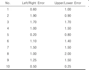
(4) Investigation About Quality Control of General X-ray System. Table 2. Hospital of kilovoltage test No.. kVp. PAE(%). kVp. PAE(%). Table 3. Clinic & hospital of mR/mAs output test kVp. PAE(%). No.. Clinic PRV(%). Hospital PRV(%). 1. -3.06. 13. 17. 1. 8.02. 8.35. 2. 3.4. 3.36. 3.85. 2. 4.02. 2.91. 3. 1. -0.54. -0.65. 3. 20.4. 2.69. 4. -2.85. 1.02. 0.42. 4. 18.0. 3.16. 5. -0.38. -0.43. -0.50. 5. 28.6. 2.33. -0.92. 6. 9.86. 9.27. -. 7. 22.2. 0.75. 6. 80. 7. -0.63 -3.25. 100. -0.93 -3.77. 120. 8. -4.58. -5.5. -. 8. 19.5. 0.14. 9. -0.46. -0.27. -. 9. 5.50. 0.60. 10. -0.29. -2.67. -. 10. 33.5. 0.57. 11. -5.54. -5.77. -. 11. ×. 0.97. 12. -1.33. -1.27. -. 12. ×. 0.64. Table 4. Clinic of light filed/beam alignment(unit : %). Table 5. Hospital of light filed/beam alignment(unit : %). No.. Left/Right Error. Upper/Lower Error. No.. Left/Right Error. Upper/Lower Error. 1. 0.60. 1.00. 1. 1.30. 0.60. 2. 1.90. 0.90. 2. 1.00. 0.60. 3. 1.70. 1.70. 3. 0.50. 0.25. 4. 1.00. 1.50. 4. 0.75. 2.00. 5. 0.20. 0.80. 5. 0.20. 1.00. 6. 1.10. 1.40. 6. 0.50. 0.40. 7. 1.50. 1.50. 7. 0.50. 0.10. 8. 1.00. 2.00. 8. 1.00. 0.50. 9. 1.25. 1.50. 9. 0.10. 0.20. 10. 0.50. 0.25. 10. 0.40. 0.10. 11. 0.00. 2.00. 12. 1.80. 1.50. 3. Light filed/Beam alignment test As a result of difference test of X-ray beam alignment and beam alignment, 10% of clinic and 17% of hospital show abnormality(Table 4, 5).. 4. Reproducibility of exposure dose test As a result of reproducibility of exposure dose. 160 Korean J Digit Imaging Med, Vol. 13 No. 4 December 2011. test, all hospital show normality while clinic show the more problems when exposure dose duration is the shorter(Table 6, 7).. 5. Half Value Thickness Test As a result of half value thickness test, all the medical institutions show normal values(Table 8)..
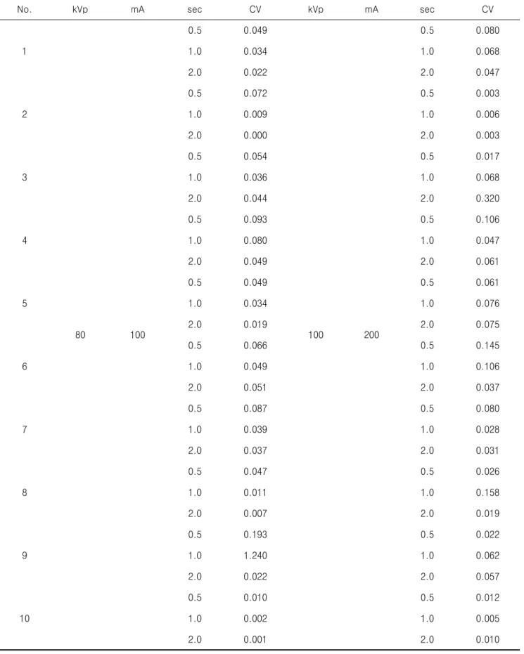
(5) Byung Sam KangㆍJin Hyun SonㆍKyung Rae Dong. Table 6. Clinic of exposuer repeatability No.. kVp. mA. 1. 2. 3. 4. 5 80 6. 7. 8. 9. 10. sec. CV. 0.5. kVp. sec. CV. 0.049. 0.5. 0.080. 1.0. 0.034. 1.0. 0.068. 2.0. 0.022. 2.0. 0.047. 0.5. 0.072. 0.5. 0.003. 1.0. 0.009. 1.0. 0.006. 2.0. 0.000. 2.0. 0.003. 0.5. 0.054. 0.5. 0.017. 1.0. 0.036. 1.0. 0.068. 2.0. 0.044. 2.0. 0.320. 0.5. 0.093. 0.5. 0.106. 1.0. 0.080. 1.0. 0.047. 2.0. 0.049. 2.0. 0.061. 0.5. 0.049. 0.5. 0.061. 1.0. 0.034. 1.0. 0.076. 2.0. 0.019. 2.0. 0.075. 100. 100. mA. 200. 0.5. 0.066. 0.5. 0.145. 1.0. 0.049. 1.0. 0.106. 2.0. 0.051. 2.0. 0.037. 0.5. 0.087. 0.5. 0.080. 1.0. 0.039. 1.0. 0.028. 2.0. 0.037. 2.0. 0.031. 0.5. 0.047. 0.5. 0.026. 1.0. 0.011. 1.0. 0.158. 2.0. 0.007. 2.0. 0.019. 0.5. 0.193. 0.5. 0.022. 1.0. 1.240. 1.0. 0.062. 2.0. 0.022. 2.0. 0.057. 0.5. 0.010. 0.5. 0.012. 1.0. 0.002. 1.0. 0.005. 2.0. 0.001. 2.0. 0.010. Korean J Digit Imaging Med, Vol. 13 No. 4 December 2011 161.
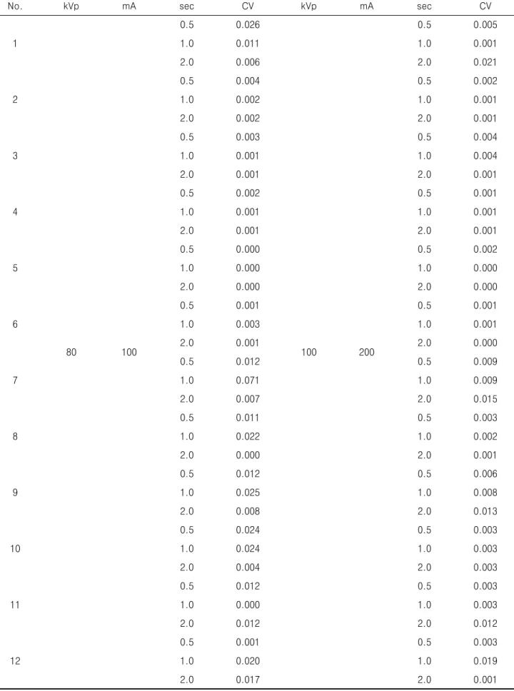
(6) Investigation About Quality Control of General X-ray System. Table 7. Hospital of exposuer repeatability No.. kVp. mA. 1. 2. 3. 4. 5. 6 80 7. 8. 9. 10. 11. 12. 100. sec. CV. 0.5. sec. CV. 0.026. 0.5. 0.005. 1.0. 0.011. 1.0. 0.001. 2.0. 0.006. 2.0. 0.021. 0.5. 0.004. 0.5. 0.002. 1.0. 0.002. 1.0. 0.001. 2.0. 0.002. 2.0. 0.001. 0.5. 0.003. 0.5. 0.004. 1.0. 0.001. 1.0. 0.004. 2.0. 0.001. 2.0. 0.001. 0.5. 0.002. 0.5. 0.001. 1.0. 0.001. 1.0. 0.001. 2.0. 0.001. 2.0. 0.001. 0.5. 0.000. 0.5. 0.002. 1.0. 0.000. 1.0. 0.000. 2.0. 0.000. 2.0. 0.000. 0.5. 0.001. 0.5. 0.001. 1.0. 0.003. 1.0. 0.001. 2.0. 0.001. 2.0. 0.000. 0.5. 0.012. 0.5. 0.009. 1.0. 0.071. 1.0. 0.009. 2.0. 0.007. 2.0. 0.015. 0.5. 0.011. 0.5. 0.003. 1.0. 0.022. 1.0. 0.002. 2.0. 0.000. 2.0. 0.001. 0.5. 0.012. 0.5. 0.006. 1.0. 0.025. 1.0. 0.008. 2.0. 0.008. 2.0. 0.013. 0.5. 0.024. 0.5. 0.003. 1.0. 0.024. 1.0. 0.003. 2.0. 0.004. 2.0. 0.003. 0.5. 0.012. 0.5. 0.003. 1.0. 0.000. 1.0. 0.003. 2.0. 0.012. 2.0. 0.012. 0.5. 0.001. 0.5. 0.003. 1.0. 0.020. 1.0. 0.019. 2.0. 0.017. 2.0. 0.001. 162 Korean J Digit Imaging Med, Vol. 13 No. 4 December 2011. kVp. 100. mA. 200.
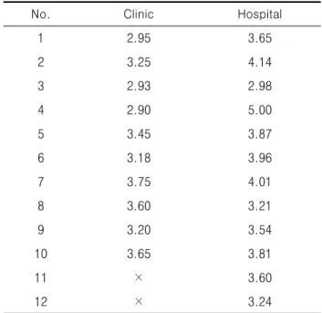
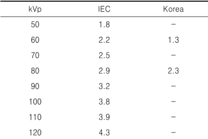
(7) Byung Sam KangㆍJin Hyun SonㆍKyung Rae Dong. 7~10. Table 8. Clinic & Hospital half value layer test (unit. which are appropriate for imaging diagnosis.. : ㎜Al). This may increase unnecessary radioactive exposure to patients. In the mAs test, a significantly. No.. Clinic. Hospital. 1. 2.95. 3.65. 2. 3.25. 4.14. 3. 2.93. 2.98. 4. 2.90. 5.00. 5. 3.45. 3.87. irradiation towards the not designated areas :. 6. 3.18. 3.96. Therefore, it increases unnecessary dose to a. 7. 3.75. 4.01. patient. 8. 3.60. 3.21. diagnosis. In the reproducibility of exposure dose. 9. 3.20. 3.54. test, all hospital show normality while clinic show. 10. 3.65. 3.81. serious problems.11 This may increase unnecessary. 11. ×. 3.60. radiological exposure and medical costs as it may. 12. ×. 3.24. larger. number. of. clinic. show. failure. than. hospital. It is because of deterioration and lack of regularly quality control. In the difference test of beam alignment slighter. than. and. and light. that. can. in. result. filed. hospital.. in. in clinic This. incorrect. is. causes. imaging. require a retake due to unstable X-ray image density at each imaging. The entire clinic and hospital show a normal half value thickness. It indicates that there is little unnecessary dose to a. Ⅳ. Discussion. patient due to soft lines. As shown in a foreign Test results show there are differences depend-. research(Table 9), the quality deterioration of. ing on medical institutions. However, in the tube. equipment is an important factor of inappropriate. voltage test, the higher is the tube voltage, the. picture quality for imaging diagnosis.. more errors show the both institutions.3~6 This. This Table 10 was HVL according to permissible. can cause more serious problems because radiation. range where were IEC(International Electronical. operators may readjust the taken images by using. Commission) and Korea. The result of HVL test. PACS or changing conditions based on their own. indicated that was showed normal figure at IEC. experiences in order to obtain necessary images. and Korea regulation.. 12. Table 9. Reasearch report Research report. Failure rete. Blue Shield. 50%. Du Pont. 13%. Berry & Oliver. 5.3%. Main cause Fault of radiologist's skill, Declining performance of equipment Declining performance of equipment Exposure condition fail, Mechanical trouble Exposure condition fail,. Micknley & McCauley. 8.9%. Mechanical trouble, Badness of maintanance and management. Korean J Digit Imaging Med, Vol. 13 No. 4 December 2011 163.
(8) Investigation About Quality Control of General X-ray System. Table 10. IEC 60601-2-40(2000-01) Particular require-. 4. Kim MH, Kim CB, Ji YS, Dong KR, Evaluation. ments for the safety of X-ray equipments(unit : mmAl). of Clinical Image on Observational Condition in Mammography. Korean J Digit Imaging Med. kVp. IEC. Korea. 50. 1.8. -. 60. 2.2. 1.3. 70. 2.5. -. 80. 2.9. 2.3. 90. 3.2. -. olitan City. J Korea Asso Radiat Prot 2010;. 100. 3.8. -. 35: 34-42.. 110. 3.9. -. 6. Park JH, Im IC, Dong KR, Kang SS. A. 120. 4.3. -. Performance Evaluation of Diagnostic X-ray. 2010; 12: 89-98. 5. Dong KR, Lee SJ, Kweon DC, Goo EH, Jung JE,. Lee. KS.. Actual. Condition. of. Quality. Control of X-ray Imaging System in Primary Care Institution: focused on Gwangju Metrop-. Unit Depends on the Hospitals Size. J Korea Asso Radiat Prot 2009; 34: 31-6.. Ⅴ. Conclusion. 7. Kim CB, Dong KR, Chung WK, Ryu YH. Analysis on Difference Between X-ray Field. In the modern medical field, diagnostic radiation generating devices are necessary tolls. Therefore, it is neccessary to establish an environment where patients. can. be. high. quality. of. imaging. by. and Light Field. J of Advanced Engineering and Technology 2010; 3: 481-4. 8. Kim HS, Jeong JH, Lee JW, Kang HD, Dong KR,. Chung. WK,. et. al.. Picture. Quality. regularly checking the quality and considerung. According to the Type of Detector in Full-field. ALARA(As Low As Reasonably Achievable) rules. Digital Mammography. Journal of the Korean. based on otimized radioactive exposure.. Physical Society 2011; 58: 364-71. 9. Stanton L, Lightfood MA, Mann S. A Pen-. References. etrometer for field kV calibration of diagnostic X-ray machine. Radiology 1966; 87: 87-98.. 1. Higashida Y, Moribe N, Morita K, Katsuda N,. 10. Baorong Y, Kramer HM, Selbach HJ, Lange B.. Hatemura M, Takada T, et al. Detection of. Experimental determination of practical peak. subtle microcalcifications: comparison of compu-. voltage. Br J Radiol 2000; 73: 641-9.. ted radiography and screen-film mammography. Radiology 1992; 183: 483-6.. 11. Ramirez-Jimenez FJ, Lopez-Callejas R, BenitezRead JS, Pacheco-Sotelo JO. Considerations. 2. Hong DH, Jung HR, Lim CH. A Comparative. on the measurement of practical peak voltage. Study on Image Quality of Breast Image Tests. in diagnostic radiology. Br J Radiol 2004; 77:. using ACR Phantom. Journal of Korean Society. 745-50.. of radiological technology 2006; 29: 241-7. 3. Shaw CC, Wang T, King JL, Breitenstein DS, Chang. TS,. Harris. KM,. et. al.. Computed. radiography versus screen-film mammography in detection of simulated microcalcifications: a receiver operating characteristic study based on phantom images. Acad Radiol 1998; 5: 173-80.. 164 Korean J Digit Imaging Med, Vol. 13 No. 4 December 2011. 12. International Electrotechnical Commission. Particular requirements for the safety of X-ray equipments; 2000. Contract No.: IEC 60601-2-40..
(9)
수치

+3
관련 문서
본 기고에서는 방사광 X-선을 이용한 고도분석법으로 대표적인 in-situ X-선 회절 (X-ray diffraction, XRD) 과 X-선 흡수분광법 (X-ray absorption spectroscopy,
Total 333 medical institutions (included in Seoul, Gyeonggi-do, Jeolla, Chungcheong, Gangwon-do, Busan area), were investigated in relation to the status of the X-ray
Total 333 medical institutions (included in Seoul, Gyeonggi-do, Jeolla, Chungcheong, Gangwon-do, Busan area), were investigated in relation to the status of the X-ray beam
Finally, jointly taking the advantages of global contrast enhancement and local contrast enhancement methods we obtain an improved X-ray image suitable for
Analyzed results of error frequency for simulation X-ray examination procedure.. Analyzed results of error frequency for patient care during simulation X-ray
[1] 간접방 식 Digital X-ray Detector 는 안정성과 대면적화 동영상 , , 구현 등 우수한 system 성능으로 가장 많이 상용화가 되어 있으나 , X-ray conversion material
To develop such a revolutionary x-ray ionizer that is free of x-ray radiation and has function to control the volume of ion formation simultaneously is a goal of this research and
The examination using diagnostic x-ray equipment is one of the most useful diagnostic equipment for identifying information in the human body in diagnostic
