논문 2012-49TC-6-3
LTE-Advanced 시스템의 다중 사용자 MIMO Relay 네트워크에서 간섭 제거를 위한 Joint Precoding 기술
( Joint Precoding Technique for Interference Cancellation in Multiuser MIMO Relay Networks for LTE-Advanced System )
사란쉬 말리크
*
, 문 상 미*
, 김 보 라*
, 김 철 성**
, 황 인 태** * ( Saransh Malik, Sangmi Moon, Bora Kim, Cheolsung Kim, and Intae Hwang )
요 약
본 논문에서는 개선된 AF(Amplify-and-Forward)와 DF(Decode-and-Forward) Relay 프로토콜을 결합한 다중 사용자 MIMO (Multiple Input Multiple Output) Relay 네트워크에서 간섭 제거 기술을 논의 한다. 간섭 제거 기술은 Relay 노드가 적 용된 전체 전송 시스템의 오류 성능을 향상시키기 위해 eNB(evolved NodeB), Relay 노드(RN: Relay Node)와 UE(User Equipment)에 의해 이루어진다. 간섭 제거를 수행하기 위해 ZF(Zero Forcing), MMSE(Minimum Mean Square Error), SIC(Successive Interference Cancellation)와 OSIC(Ordered Successive Interference Cancellation)가 적용된 DPC(Dirty Paper Coding)와 THP(Thomilson Harashima Precoding)를 사용하였다. 이러한 기본적인 기술이 적용된 Relay 노드 기능들이 연구되 고 개선된다. 협력 Relay 노드에서 두 계층 간의 간섭 제거를 강화한 DF는 성능을 향상시킨다. eNB와 RN간의 가중치 벡터를 사용하여 간섭 제거가 수행된다. 연구 최종 결과, 기존의 알고리즘과 비교하여 제안된 알고리즘이 낮은 SNR에서 더 좋은 성 능을 나타냈다. 모의실험 결과 LTE-Advanced 시스템에서 제안된 기법이 오류 성능 면에서 상당한 향상을 나타냈다.
Abstract
In this paper, we perform interference cancellation in multiuser MIMO (Multiple Input Multiple Output) relay network with improved Amplify-and-Forward (AF) and Decode-and-Forward (DF) relay protocols. The work of interference cancellation is followed by evolved NodeB (eNB), Relay Node (RN) and User Equipment (UE) to improve the error performance of whole transmission system with the explicit use of relay node. In order to perform interference cancellation, we use Dirty Paper Coding (DPC) and Thomilson Harashima Precoding (THP) allied with detection techniques Zero Forcing (ZF), Minimum Mean Square Error (MMSE), Successive Interference Cancellation (SIC) and Ordered Successive Interference Cancellation (OSIC). These basic techniques are studied and improved in the proposal by using the functions of relay node. The performance is improved by Decode-and-Forward which enhance the cancellation of interference in two layers at the cooperative relay node. The interference cancellation using weighted vectors is performed between eNB and RN. In the final results of the research, we conclude that in contrast with the conventional algorithms, the proposed algorithm shows better performance in lower SNR regime. The simulation results show the considerable improvement in the bit error performance by the proposed scheme in the LTE-Advanced system.
Keywords : THP, DPC, Interference Cancellation, Cooperative Relay, LTE-Advanced
*
학생회원,
**평생회원, 전남대학교 전자컴퓨터공학과
(School of Electronics & Computer Engineering Chonnam National University)
※ 본 연구는 지식경제부 및 정보통신산업진흥원의 대학 IT연구센터 지원사업의 연구결과로 수행되었음.
(NIPA-2012-H0301-12-3005).
※ 이 논문은 2011년도 전남대학교 학술연구비 지원에 의하여 연구되었음.
접수일자: 2012년 4월 26일, 수정완료일: 2012년 6월 14일
Ⅰ. Introduction
In the recent years, relaying technology in cellular systems has received significant interest. Relays based network architectures show promising interest in potential and practical applications as Long Term Evolution (LTE)-Advanced
[1~3]
. Multiple Input Multiple-Output (MIMO) is a well-known technology for current radio networks to significantly improve the spectral efficiency and link reliability[4]
. For these reasons, a number of studies have focused on investigating relay-assisted multi antenna systems[5~
7]
.In [6~7], studies have revealed that the optimal Amplify-and-Forward (AF) relaying strategy follows a similar structure as the SVD-based precoding in MIMO systems without relays. Further in [8], the authors investigate the optimization problem of joint source precoding and relaying design. To combat the inter-cell interference, [9~11] propose for BSs to cooperate in transmitting their signals. In [10], a cooperative BS transmission scheme that uses beamforming and Dirty Paper Coding (DPC) method is considered. This work was further enhanced in [9~10], where more practical cooperative transmission schemes, employing optimum beamforming and Tomlinson Harashima Precoding (THP)
[11~12]
, were employed, to mitigate the interference in co-working wireless networks.cooperative BSs schemes increase the spectral efficiency significantly, as compared to the capacity of a conventional cellular network, their benefit is limited because of the exceeding cost of BSs
[6]
. An increasingly attractive strategy is to reduce the network cost by replacing some of BSs with Relay Stations (RS). Here, the RN receives the signals from BSs and relays these signals to Mobile Stations (MS). Such networks are called relay networks. The RN provides signal to those UE which are located at the cell edge and due to large path loss and severe shadowing effects cannot receive proper signalquality. In the previous work, Chae et al. introduced the MIMO relaying system with fixed relay networks
[13]
. They studied the achievable rates for multiuser MIMO relay system and multiuser Tomlinson Harashima Precoding (THP) for fixed relay systems. However, the direct link from eNB to UE was not considered.Since, it is hard to obtain the optimal precoding design for the relay-assisted multiuser MIMO systems, several suboptimal solutions are developed in [13~14]. More specifically, in [14], sum capacity bounds are derived for the system by exploiting non-linear precoding (DPC-ZF) at the source and linear processing at the relay. Aiming at transmit power minimization under Quality-of-Service (QoS) requirements, an iterative joint precoding algorithm is proposed in [14].
In this paper, we consider the optimization of linear pre-processing at both the source and the relay in a MIMO relay assisted multiuser downlink channel.
Different from [14], we optimize the joint precoding strategy by maximizing the error performance of our system under fixed transmit power constraints. First, we design the Zero-Forcing (ZF) and Minimum Mean Square Error (MMSE) at Relay Node (RN) with the precoding like Thomilson Harashima Precoding (THP) and Dirty Paper Coding (DPC) design at eNB.
Later on, the schemes like Successive Interference Cancellation (SIC) and Ordered Successive Interference Cancellation (OSIC) are deployed for better signal equalization and improved performance gain. For the new system we apply the new improved transmission design with Amplify-and-Forward (AF)
[15]
and Decode-and-Forward (DF) relay node. However, previous schemes were only limited in the beamforming case and its extension to the precoding case is non-trivial, which usually results in a rate performance loss especially when all the nodes are equipped with multiple antennas, due to the fact that the multiplexing gain offered by MIMO channels cannot be fully exploited. In this paper, we aim to design apractical dual hop transmit scheme which can fully exploit the multiplexing gains offered by multiple antennas. More specifically, we propose a joint precoding scheme using the criterion of optimizing the system rate or the BER performance, where the reduction of both feedback overhead and feedback delay will be fully considered. The main contribution is the improved OSIC DF with DPC precoding for interference cancellation. We compare the performance of THP in order to prove the reduced complexity design performance of our algorithm. The key factors considered in this algorithm are the detection algorithm at RN i.e. ZF and MMSE and SIC and OSIC. Conventional OSIC makes it attractive as interference cancellation by using SINR of the received signal. When we implement DPC and THP with optimized DF with OSIC the system shows better error performance with considerable gain.
The rest of the paper is organized as follows- Section-II describes system model using AF and DF protocol and problem formulation of interference amongst the users. Then section-III shows the THP and DPC used with ZF and MMSE with their improvement, section-IV shows analysis of precoding and detection technique improvement with SIC and OSIC after that section-V explain improved proposed schemes as THP and DPC with AF and DF protocol application of whole system, also it concludes main development idea of all schemes. Then in section-VI we show simulation results with bit error rate.
Finally, the conclusions are in section VII.
Ⅱ. System Model and Problem Formulation
Our System model focus on the interference problem that occurs in multiuser system. When the signal arrived at UE, it suffers a lot of interference from the other UE signals. The signal also suffers from large amount of noise and fading. The second problem arise is due to the weak signal transmission for the cell edge users. The cell edge users will always receive low
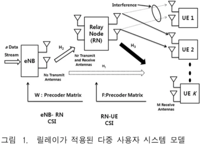
그림 1. 릴레이가 적용된 다중 사용자 시스템 모델 Fig 1. System model of relay assisted Multiuser
system.
intensity signal with reduced performance efficiency which is a very big issue to resolve in present communication system.
In our proposal, we strictly focus on improvement of relay networks in multiuser scenario. The basic function for RN is to retransmit the signals received by the eNB and allocate it to other users in the cell. As shown in Fig. 1, We use single cell system with K number of users and one RN, all User Equipments (UE) are having M transmit/receive antennas. The RN have Nr transmit/receive antennas. The eNB is provided with Ns transmit/receive antennas. We consider 2 hop communication system with direct link (
) and relay link(
and
). The precoding matrix W used for eNB-RN link and precoding matrix F used for RN-UE link. The detection techniques are performed at RN and UE. The system employed, assumes full channel state information between eNB and RN link. Our proposal design the relay network which retransmits the eNB signal with reduced interference and improved error performance.We assume complete CSI and half duplex transmission mode in this system model. Here, we just concerned with precoding and relay protocol design to cancel interference, we do not consider remote user scheduling in this paper as in [13, 14].
We use THP and DPC as precoding scheme. As depicted in Fig. 1, we consider a direct channel link
as
between eNB and UE. The channel between eNB and RN is
, the channel between RN and UE is given by
.During first time slot, eNB employs the precoding to transmit a data stream, i.e. data vector s is given by
ϵ
, to the relay station without considering loss in generality, the input symbols are normalized assuming,
, with E{·} denoting the expectation
operator. The received signal at RN becomes (1.a) and the direct link for the eNB and UE at the first phase is given by (1.b)
(1.a)
(1.b)
where, W∈C
Ns×a
denotes the precoding matrix at the eNB, we assume thattr{WW H }≤a
with tr{·} being trace operator,H 2 ∈C Nr×Ns
denotes first hop of the channel matrix between eNB and RN. W is given as the precoding matric between eNB and UE.
denotes total transmit power at the eNB and
denotes a white Gaussian noise vector with zero mean and variance
.Here, our main focus is to improve relay coverage and expansion. So, we assume that the direct path between eNB and UE is facing lot of shadowing and fading of components so the signal received is weak. In second time slot, the relay station will forward its received signal using precoding matrix
F∈C Nr×Nr
that is designed with the transmit power of
at the relay station, term Nr×Nr is used because it shows backward channel pre-processing and broadcast to UE, F must satisfy in equation (2)
≤
(2)
The received signal at RN and UE can be modeled as (3)
(3)
where,
H 3
∈CM×Nr
denotes the second hop channel matrtix between RN and UE, and
denotes a white gaussian noise vector with zero mean and variance
.Representing the eNB precoding matrix by
⋯
where
is the beam former for data sk
to user k, we can calculate SINR at user k using equation (4),
≠
∥
∥
(4)
We denote
is the 1×Nr channel vectors between the RN and the kth user terminal.
Thus, focusing the capacity maximization and considering, the joint precoding and relaying as main criteria can be given as:max F,W
(5.a)
s.t.
(5.b)
(5.c)
respectively, where factor
in the objective function
results from the fact that data is transmitted from two time slots. The optimization is simple to apply, but it is difficult to obtain globally optimum solution in this case. The iterative algorithm proposed with DPC and THP and MMSE and OSIC makes it simpler to solve mathematically using linear calculations.
Ⅲ. Proposed Algorithm with THP ZF & MMSE and DPC ZF & MMSE
The conventional schemes for multiuser case are designed in this section. The basic detection scheme
as ZF and MMSE are employed with THP and DPC.
The THP and DPC are best known for interference suppression in multiuser MIMO system. We implement interference cancellation using RN which helps is to multiply the received signal weighted vector at RN by improving the power.
In order to reduce the transmit symbols to the particular boundary region in THP we use the modulo operation
[16]
.
(6)
for QPSK and
for 16-QAM.However, in spite of the modulo operation, THP still causes transmit power increase. As the modulation size increases the precoding loss decreases [17].
From, B the feedback matrix, F the precoded matrix and G post processing diagonal matrix, that can be obtained by channel equalization. G can be evolved as QR factorization matrix on H
eq
which shows the equalized channel vector as per given in [17], we obtain (7) as
(7)
where, Q is unitary matrix, and R = [r
i,j
] is a upper triangular matrix. So, the THP-ZF is given by (8)
(8.a)
(8.b)
(8.c)
On obtaining the expression for the ZF and MMSE for THP we assume, M ≧ 2K (M= no. of transmit Antennas, K= no. of users served in one specific cell). In order to reduce redundancy we will directly focus on the received signal vectors at the UE. Given by equation (9), where we have to combine the weights of the eNB and RN link to setup appropriate multiuser relay system.
Now, we consider w
1
and w2
as the weighted vectors for eNB-RN and the RN-UE link. The factor to improve the performance gain has high importance in this scenario. Therefore, the combining method for channel gain and SINR is important. So we derive the aspect in equation (9), for the ith
user case
∥
∥
(9.a)
∥
∥
(9.b)
Using the weighted vectors we obtain the performance at the UE.
For the case of THP-MMSE, we consider orthogonality principle as to nullify the effect of channel inversion and noise increment caused in THP-ZF. The THP-MMSE is given as follows (10):
(10.a)
(10.b)
(10.c)
And the weighted vectors for the THP-MMSE for i
th
User is given by (11):
∥
∥ ∥
∥
∥
∥
(11.a)
∥
∥
∥
∥
∥
∥
(11.b)
In case of DPC, the previous researches [18] have proved it to be near suboptimal technique in terms of achievable gain. The information and theoretic analysis prove DPC more optimal with detection
techniques as ZF and MMSE. Also, the performance enhancement is observed in this case.
The equations for receiver and transmitter are designed as equations (1) and (3). So, we simply go for the design of DPC with ZF and MMSE techniques.
In DPC, user data is successively encoded with knowledge of interference caused by previously encoded users. The interference is cancelled by the QR decomposition of the channel matrix H. The effect of noise in the channel
,
and
are considered separately. Denoting the encoded signal vector
between eNB and RN for the first time slot and the precoded matrix as W at the RN in equation (12), the signal weighted vectors for the UE matrix become same as equation (10) and (12).The precoding operation must perform cooperatively. So, for the encoded signal S and precoder matrix F is given by, (12)
(12.a)
for F precoder matrix,
(12.b)
The signal vector S
1
, at RN is received as
For F precoder matrix
for the second time slot. In our scheme when the signal is again precoded between the link RN and UE. Now, in second time slot the matrix W is replaced by matrix F and the weighted vector equation is successively multiplied with the relay equation (22), (23) and (25), (26) stated in section-V.
The equation will modify by transmitted signal S=FX and UE received signal becomes as .
In case of detection, the difference is with QR decomposition in case of DPC-ZF and DPC-MMSE.
The rest method with the weighted vectors that are used to calculate the signal matrices are same. The Hermitian H for this case is given by,
, where R is the upper triangular and Q is unitary matrix. Note that we take QR decomposition to the Hermitian of the channel matrix H suitable for the receivers to eliminate the need of receive filters [19].We choose precoding matrix W and F as Q which satisfy the power constraint in (13). The power constraint remains same for precoder matrix F.
≤ (13)
where ∙
shows matrix Hermitian Transpose.IV. Proposed Algorithm with THP SIC & OSIC and DPC SIC & OSIC
The THP and DPC matrix works in same way as in case of ZF and MMSE in equations (8-10). The main difference occurs in the case of receive signal value for decision and decoding. In this section, we will consider the received value as Y
RN
and YUE
for the RN and the UE node. In SIC, the receiver arbitrarily takes one of the estimated symbols S, and subtracts its effect from the received symbols as in equation (1) and (3). However, a better BER performance can be achieved by subtracting the interference effect of
and
. To make that decision, we find out the transmit symbol which came high power at the receiver (RN and UE). The
is the vector received at the RN and
is그림 2. SIC와 OSIC 검출 과정.
Fig. 2. SIC and OSIC detection and processing.
processed at the UE link which is further used to improve the channels state information of the system as in figure 2.
For SIC, let Y
RN
and YUE
be received signals as (14) which tries to find the coefficient matrix W and F that minimize the statistical expectation of the signal estimation error successively. The processing for Y at RN is performed as:
(14.a)
(14.b)
where E{·} is the expectation operator.
As the estimation of
and
is the main issue in our algorithm, we will directly focus on that part.As given in equation (15), we will use the parameters for both of the precoder matrix W and F like their channel coefficients. So, if the value of
>
, the received signal value is given by
, by further simplification it can be shown as (15)
(15)
where, similarly the
(16)
For the case of OSIC, we use (17), and the weighted vectors for the above equation (9) and (11) are used for the above equations (15) and (16). Here, we propose a new OSIC THP algorithm for multiuser relay system from the improvement of [20]. Figure 3, explains the formulation of THP calculation with SIC and OSIC, the input and output and MOD operation is also represented with the data calculation of FG matrix.
The implementation of LQ decomposition to the
그림 3. SIC와 OSIC을 위한 eNB와 RN의 원본 데이터 를 재 정렬하는데 사용되는 순열 행렬 P.
Fig. 3. A permutation matrix P is used to reorder original data in eNB and RN for SIC and OSIC.
permutated channel matrix PH
eq
, we obtain (17),
(17)
where, P is the permutation matrix. Choose precoding Matrix as
, then
corresponding channel effect where
shows feedback channel information. By reordering the transmitted data correspondingly, the received signal vector becomes (18),
(18)
The difference with THP model than DPC is for THP-OSIC is that it is little more complex than THP-SIC.
The details of the formulation of this method is explained in the algorithm stated:
Algorithm: SIC and OSIC with THP and DPC case.
For (i=1, …, 2K) {
1- Make
consist of uncompressed rows of
∙ ′
and ′ = 0.2- Project each row of to the null vector space of other rows.
3- Set the row of precoding matrix.
4- Move this row to the row of assign buffer processed .Move the data of step 4 to row of }
The permutated channel and transmitted data are obtained in the algorithm as H
eq
and ′.V. Proposed schemes of Interference Cancellation in Amplify-and-Forward (AF)
and Decode-and-Forward (DF) Protocol Design
1. Amplify-and-Forward (AF) Protocol Proposed Design
Amplify-and-Forward(AF) relay is the basic relay design proposed in 3GPP LTE-Advanced due to its simple application. The basic AF relay proposed in [20] is improved in our research study in this paper.
For AF the system implement the amplification factor β is given as
(19)
We multiply the amplification factor with the received signal vector at RN and then retransmit the improved signal using the precoded signal matrices.
Proposed AF design protocol is capable of cancelling interference at the RN. In this paper, the average received SINR is supposed to be determined by the propagation gain from the transmitter to the receiver.
The un-faded SINR is given by (20)
(20)
For the proposed schemes in section III and section IV, we consider a new power amplification factor for the detection and precoding technique. The different diagonal elements of
G
result in a implicit fairness-guaranteed power loading operation of the precoding matrix F, which allocates more power to the worse subchannel and therefore guarantees fairness among users. The new value of the amplification factor becomes
(21)
where, K is the number of users and
is the channel gain from the ith subchannel which is chi-square distribution of degree of freedom 2(K-i+1).In our system, we implement the relay with the detection techniques as ZF & MMSE and the proposed improved SIC & OSIC with THP and DPC, for the multiuser MIMO relay system. Such that, the relay will only amplify the signals which are properly estimated by the SINR estimator in (22), which are lately re-encoded and transmitted to the UE. The received SINR at the relay becomes (22) and (23) where a and b are given as the link between eNB to RN and RN to UE, respectively:
(22)
(23)
2. Decode-and-Forward (DF) Protocol Proposed Design
The Decode-and-Forward(DF) is supposed to process the whole signal and decode then re-encode the symbols based on the best SINR from each link.
At the first time slot, a signal destined for the eNB-RN link is broadcasted and delivered to the UE.
Thus, the selected direct link user can detect that signal in this time. For the proposed protocol design, we employ the DF relaying scheme at the RN in which the RN detects the received relaying signal before forwarding it at the second time slot. By doing so, the RN can eliminate the interference by subtracting the broadcasted signal from the received signal at the second time slot. If the link quality from the eNB to RN is better than RN to UE, the RN can perfectly cancel out the interference since the relaying signal,
, can be detected correctly.Considering that
and
as the received signal at the second time slot and estimate of the relayingsignal at the UE, respectively, the proposed interference cancellation scheme eliminates the interference by (24):
(24)
Let
be the SINR of the user K (RN-UE link) without any interference,
⁄ (25)
and
is the SINR of the eNB-RN link defined as
⁄ (26)
A capacity upper bound for the DF mode can be obtained by considering the case of
(27)
The new improved decode and forward design use the high SINR value detection method at relay which use soft decoding of the symbol. After the DF processing the proposed system is capable of exhibiting excellent performance at the receive nodes.
The new estimation and decode and forward relay also reduces the processing delay as it compares only the value of SINR and if the equation (27) becomes untrue or equal there is no need of further symbol decoding and the signal is forwarded directly to the allocated user. But, the value at the SINR
DF
increases if the number of user K in the cell increases.VI. Simulation Results
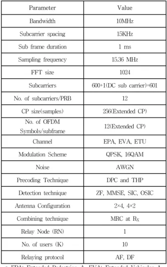
The simulation results are based on the link level Monte Carlo simulations. The system is half duplex mode. Noise components are same at all channel links but channel fading components change increase and decrease based on the links as eNB-RN link and RN –UE link characteristics. The simulation parameters are based on 3GPP LTE-Advanced 10 MHz bandwidth.
In Fig. 4, the performance of ZF and MMSE shows the best results with DPC-AF-MMSE, but at
Parameter Value
Bandwidth 10MHz
Subcarrier spacing 15KHz
Sub frame duration 1 ms
Sampling frequency 15.36 MHz
FFT size 1024
Subcarriers 600+1(DC sub carrier)=601
No. of subcarriers/PRB 12
CP size(samples) 256(Extended CP) No. of OFDM
Symbols/subframe 12(Extended CP)
Channel EPA, EVA, ETU
Modulation Scheme QPSK, 16QAM
Noise AWGN
Precoding Technique DPC and THP Detection technique ZF, MMSE, SIC, OSIC Antenna Configuration 2×4, 4×2
Combining technique MRC at RX
Relay Node (RN) 1
No. of users (K) 10
Relaying protocol AF, DF
* EPA: Extended Pedestrian A, EVA: Extended Vehicular A, ETU: Extended Typical Urban B
표 1. 모의실험 파라미터.
Table 1. Simulation Parameters.
그림 4. ZF과 MMSE 기술이 적용된 DPC와 THP 기법 과 결합된 AF relay BER 성능.
Fig. 4. BER performance of AF relay with DPC and THP schemes using ZF and MMSE techniques.
the lower SNR the system suffers high complexity and the link result improvement is observed. The results show very close performance of THP-AF-MMSE and DPC-AF-MMSE but a large difference when observed with ZF in case of THP and DPC. This clearly proves that there is high interference and noise cancellation performance in the proposed AF design which also reduces the system complexity. The No Relay states the performance for the direct link users.
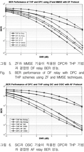
In Fig. 5, the DF relay shows the outstanding performance and also shows drastic difference in the complexity reduction with interference cancellation.
그림 5. ZF과 MMSE 기술이 적용된 DPC와 THP 기법 과 결합된 DF relay BER 성능.
Fig. 5. BER performance of DF relay with DPC and THP schemes using ZF and MMSE techniques.
그림 6. SIC과 OSIC 기술이 적용된 DPC와 THP 기법 과 결합된 AF relay BER 성능.
Fig. 6. BER performance of AF relay with DPC and THP schemes using SIC and OSIC techniques.
The main issue of THP and DPC is complexity which was observed in case of AF relay is removed in this case of proposed DF. The DF protocol exhibits excellent performance due to the proposed decoding mechanism in DF which only decodes best received symbols at the DF node.
In Fig. 6, the system shows the performance of AF protocol with SIC and OSIC. The AF protocol shows the improvement in the basic scheme but the complexity reduction is still issue in this case. The noise amplification is the problem persist for AF relay. The AF protocol performance is improved as the complexity reduction is observed at the lower SNR regimes. The AF protocol noise enhancement is much controlled when allied with OSIC. The prior cancellation of interference by selection the only best symbols with highest SINR at the RN.
In Fig. 7, the DF protocol shows the best performance with OSIC scheme. This shows that the proposed DF protocol has the best efficiency to reduce system complexity and exhibit the best performance with interference cancellation. The proposed schemes shows best performance with DPC as it can be observed clearly that at the higher SNR regime the BER performance exhibits drastic improvement and achieves considerable gain in BER performance at lower SNR.
그림 7. SIC과 OSIC 기술이 적용된 DPC와 THP 기법 과 결합된 DF relay BER 성능.
Fig. 7. BER performance of DF relay with DPC and THP schemes using SIC and OSIC techniques.
Ⅶ. Conclusions
In this paper, we propose the joint precoding scheme with detection techniques for interference cancellation at the relay node. The proposed algorithm is for half duplex relay system in which the relay node cooperates the eNB for interference cancellation in multiuser system network.
The proposed scheme employs detection techniques with interference cancellation using THP and DPC precoding schemes. We implement a new algorithm specially for multiuser sy stem case with AF and DF protocol which employs successive interference cancellation with ordered successive interference cancellation using precoded weighted matrix and weighted vectors at the relay nodes of THP and DPC.
Simulations results show that the improved AF and DF protocols provide considerably better error performance with new SIC and OSIC.
References
[1] R. Pabst, B. H. Walke, D. C. Schultz, et al.,
“Relay-based deployment concepts for wireless and mobile broadband radio,” IEEE Commun.
Mag., vol. 42, no. 9, pp. 80–89, Sep. 2004.
[2] S. W. Peters, A. Y. Panah, Kien T. Truong, and R. W. Heath, Jr., “Relay architectures for 3GPP LTE-advanced,” EURASIP J. Wirel. Commun.
and Network., vol. 2009, Article ID 618787, 14 pages, 2009.
[3] S. Sesia, I. Toufik, and M. Baker, LTE, The UMTS Long Term Evolution: From theory to practice, Wiley & Sons, Feb. 2009.
[4] E. Telatar, “Capacity of multi-antenna Gaussian channels,” European Trans. Telecommun., vol.
10, pp. 585–598, Nov. 1999.
[5] B. Wang, J. Zhang, and A. Høst-Madsen, “On the capacity of MIMO relay channels,” IEEE Trans. Inf. Theory, vol. 51, no. 1, pp. 29–43, Jan. 2005.
[6] X. Tang and Y. Hua, “Optimal design of non-regenerative MIMO wireless relays,” IEEE Trans. Wirel. Commun., vol. 6, no. 4, pp. 1398–
1407, Apr. 2007.
[7] O. Mu˜noz-Medina, J. Vidal, and A. Augst´ın,
“Linear transceiver design in nonregenerative relays with channel state information,”
[8] Y. Huang, L. Yang, and B. Ottersten, “A limited feedback joint precoding for amplify-and-forward relaying,” IEEE Trans. Signal Process., accepted to appear, 2009.
[9] W. Hardjawana, B. Vucetic, and Y. Li,
“Cooperative precoding and beamforming in co-working wlans,” ICC 2008 proceedings, pp.
4759–4763, Oct. 2008.
[10] W. Hardjawana, B. Vucetic, and Y. Li,,
“Cooperative procoding and beamforming for co-existing multiuser MIMO systems,” IEEE ICC, 2009.
[11] G. J. Foschini, K. Karakayali, and R. Valenzuela,
“Coordinating multiple antenna cellular networks to achieve enormous spectral efficiency,” IEEE Proceedings on Communications, vol. 153, no. 4, pp. 548–555, Aug. 2006.
[12] M. Tomlinson, “New automatic equalizer employing modulo arithmatic,” IEEE Electronic Letters, vol. 7, pp. 138–139, 1971.
[13] C. B. Chae, T. Tang, R. W. Heath Jr., and S.
Cho, “MIMO relaying with linear processing for multiuser transmission in fixed relay networks,”
IEEE Trans. Signal Processing, vol. 56, no. 2, pp. 727-738, Feb. 2008.
[14] R. Zhang, C. C. Chai, and Y. C. Liang, “Joint beamforming and power control for multiantenna relay broadcast channel with QoS constraints,”
[15]“Amplify-and-forward relaying in wireless communication network.” By Alireza Shahan Behbahani, University of California, Irvine.
[16] F.A. Dietrich, P breun, and W. Utshick, “Robust Thomilson Signal Processing”, vol. 55, no. 2,pp 631-644, Feb 2007.
[17] R.F.H. Fishcer, Precoding and signal Shaping for Digital transmission, NewYork : John Wiley
& Sons, 2002
[18] M.H.M Costa “Writing on a Dirty Paper”, IEEE Transactions on Information theory, vol IT -29, pp 439-441, may 1983.
[19] R.F. Fishcher, C Windpassinger, A Lampe, and J,B Huber,“MIMO Precoding for decentralized recivers”.
[20] R. F. H. Fischer, J. B. Huber, and C.
Windpassinger, “Precoding for point-to- multipoint transmission,” in Proc. Eight International Workshop on Signal Processing for Space Communications, 2003, pp. 137–144.
저 자 소 개 사란쉬 말리크(학생회원)
2010년 라지프 간디 공과대학 IT학과 학사
2011년 3월∼현재 전남대학교 전자컴퓨터공학과 석사과정
<주관심분야 : MIMO, OFDM, Relay>
김 보 라(학생회원) 2012년 2월 전남대학교
전자컴퓨터공학부 학사 2012년 3월∼현재 전남대학교
전자컴퓨터공학과 석사과정
<주관심분야 : 이동통신, CoMP>
황 인 태(평생회원) 1990년 2월 전남대학교 전자공학과 학사 1992년 8월 연세대학교 전자공학과 석사 1999년 9월 ~ 2004년 2월 연세대학교
전기전자공학과 박사 1992년 8월~2006년 2월 LG전자 책임 연구원 2006년 3월~현재 전남대학교 전자컴퓨터공학부
교수
<주관심분야 : 디지털통신, 무선통신시스템,
mobile terminal system for next generation, physical layer software for mobile terminal, efficient algorithms for AMC, MIMO and MIMO-OFDM, Relaying scheme for wireless communication>
문 상 미(학생회원)
2012년 2월 전남대학교 전자컴퓨 터공학부 학사
2012년 3월∼현재 전남대학교 전 자컴퓨터공학과 석사과정
<주관심분야 : 이동통신, ICIM>
김 철 성(평생회원)
1987년 Univ. of Arizona(박사) 1987년∼1989년 한국전자통신
연구원
1989년∼현재 전남대학교 전자컴퓨터공학부 교수
<주관심분야 : 이동통신, 디지털통신, MIMO, OFDM, RFID>