• 검색 결과가 없습니다.

Quasi-Distributed Temperature Sensor Based on a V-Grooved Single-Mode Optical Fiber Covered with Ethylene Vinyl Acetate

N/A
N/A
Protected

Academic year: 2021

Share "Quasi-Distributed Temperature Sensor Based on a V-Grooved Single-Mode Optical Fiber Covered with Ethylene Vinyl Acetate"

Copied!
5
0
0

로드 중.... (전체 텍스트 보기)

전체 글

(1)

Abstract

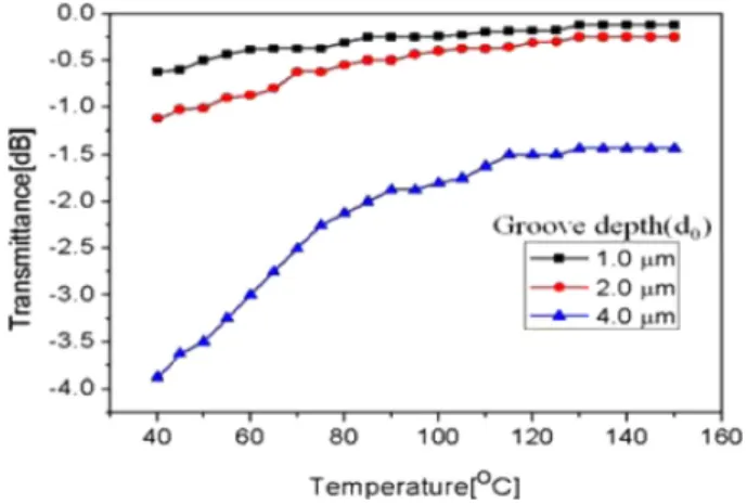
In this study, a V-grooved single-mode fiber along with optical time domain reflectometry (OTDR) as a quasi-distributed temperature sensor was investigated. The external medium used to fill the V-groove affects the optical mode. The V-groove was filled with ethylene vinyl acetate (EVA) because its transmittance was sensitive to temperature. The experimental results showed that the optical loss of the sensor varies with temperature, and the sensitivity depends on the depth of the V-groove.

Keywords: V-grooved single-mode fiber, Distributed temperature sensor, Ethylene vinyl acetate, Optical time domain reflec- tometry

1. INTROUDCTION

Capability of multi-point or distributed sensing is one of the key advantages of optical fiber sensor systems. optical time domain reflectometry (OTDR) techniques based on Raman scattering [1,2] and Brillouin scattering [3,4] are well-known distributed temperature sensing methods. A key advantage of these methods is the ability of the optical fiber to simultaneously operate as a sensor and as a signal path. This enables measurement of highly accurate data, such as, temperatures or strains at any point along the optical fiber.

However, these methods suffer from long time duration for data acquisition and processing because of very weak optical signal, and high installation cost of the sensor system. Furthermore, the sensing range of the these systems is limited to 10 km [1, 3]. Fiber bragg grating (FBG) is often used in fiber optic quasi-distributed sensor systems. However, this method requires an expensive spectrometer or interrogator to interpret the measured data [5,6], in addition to the complicated fabrication process of the FBG

sensor.

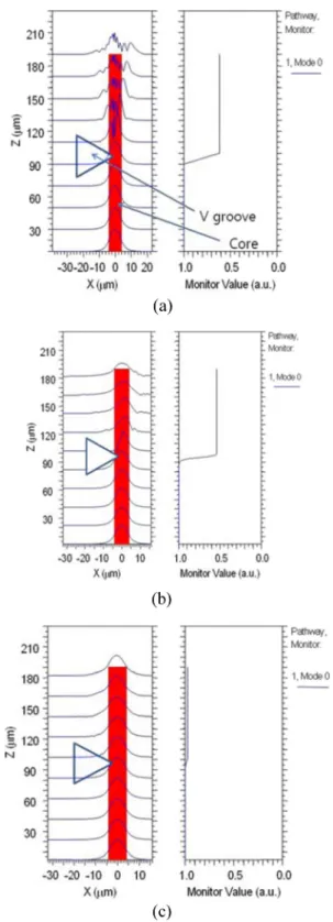
In this paper, we propose a simple V-grooved single-mode fiber as an element of quasi-distributed fiber-optic sensor. The side portion of a single-mode fiber was removed in the V- shaped form, and a small portion of the core was cut along the edge of the V-groove. The V- groove can be inscribed on the optical fiber by a very simple fabrication process by using the general dicing machine used for wafer cutting. In addition, the sensor signal can be detected by general OTDR based on Rayleigh scattering. The V-grooved fiber was applied to the multi-point single-mode fiber sensor using a medium whose transmittance was sensitive to temperature. Ethylene vinyl acetate (EVA), generally used for bonding, was used as the V- groove filling medium. The transmittance of EVA increases with an increase in the surrounding temperature. The filling medium affects the core mode leading to an inherent optical loss in the V-groove. The sensor proposed in this study is based on optical loss modulation due to the temperature variations around the filling medium. The number of sensing points and sensitivity of the sensor can be determined by controlling the specifications of the V-groove. The performance of the proposed sensor was examined by using general OTDR based on Rayleigh scattering. The shortcomings of both the Raman and Brillouin OTDR, including the high cost, long measurement time, and short sensing distance can be overcome by employing the proposed sensor. In addition, the proposed quasi-distributed sensor system based on V-grooved optical fibers is advantageous in terms of implantation cost because of the easy fabrication process of the sensor, and

1

Department of Electronic Engineering, Honam University, 506-714 Seobongdong, Gwang san-gu, Gwangju, Korea

2

Department of Mechatronics, Cheongju Korea polytechnic #54 Sandonro, Heungduk-gu, Cheongju-city, Chungbuk 361-857, Korea

+

Corresponding author: [email protected]

(Received: May. 14 2014, Revised: Jul. 7, 2014, Accepted: Jul. 9, 2014)

This is an Open Access article distributed under the terms of the Creative Commons Attribution Non-Commercial License(http://creativecommons.org/

licenses/bync/3.0) which permits unrestricted non-commercial use, distribution,

and reproduction in any medium, provided the original work is properly cited.

(2)

simple detection of signal using general OTDR.

2. DEVICE STRUCTURE AND TRANSMISSION CHARACTERISTICS

The V-grooved optical fiber has been applied in high-power fiber lasers for beam combining [7]. However, to the best of our knowledge, the characteristics of the device as a fiber optic sensor have not yet been reported. The schematic structure of the proposed V-grooved single-mode fiber sensor is shown in Fig. 1.

The side of the fiber was removed, and the V-groove was filled with a temperature sensitive material. It was important that most parts of the core still remained intact. The optical mode of the fiber was strongly dependent on both the groove depth and the optical transmittance of the filling medium.

The transmission characteristics of the V-grooved single-mode fiber were investigated using the beam propagation method. For the simulations, the core radius, core refractive index (nco), and cladding refractive index (ncl) were assumed to be 4.0 um, 1.450, and 1.444, respectively. In order to calculate the optical beam propagation in the V-groove, it is necessary to know the optical refractive index of the filling medium. However, it was difficult to define the refractive index of EVA because the medium might cause high optical scattering loss, and also, the loss was sensitive to temperature. The refractive index of the filling medium can be given as a complex number. Since EVA becomes more transparent as the temperature increases, the magnitude of the imaginary part of its refractive index decreases. The refractive index of the medium at 120

o

C measured by a side-polished single-mode fiber [8] was about 1.46. At this temperature, the medium was almost transparent.

Fig. 2 shows the dynamic variations of the optical mode profile (left side). It also shows the transmitted optical power (right side) along the V-grooved single-mode fiber for different refractive

indexes of the filling medium (nex) while the light travels along the fiber. The guiding condition of the optical mode changes abruptly when it encounters the V-groove, and as a result, a part Fig. 1. Schematic structure of the V-grooved optical fiber senor.

Fig. 2. Mode propagation (left side) and transmittance (right side) of the V-grooved optical fiber for different structural conditions, with d0=2 and (a) n

ex

=1.0, (b) nex=1.46+0.1i, and (c) nex

=1.46.

(3)

a highly absorbing medium was filled in the V-groove, the optical power of the guide-mode in the core was attenuated while passing the V-groove as shown in Fig. 2 (b). At low environmental temperature, the device behaves as an optical attenuator as in Fig.

2 (b). However, at high temperature, the optical mode was scarcely influenced by the medium and no considerable optical loss occurred in the V-groove as shown in Fig. 2 (c).

leakage of optical mode into the covering medium. However, in the case of the high-loss state, both leakage and absorption of the optical mode by the covering medium contribute to the optical loss. In principle, it is not easy to control the angle of V-groove during the fabrication process. In addition, the transmittance is given by the ratio of the output optical power to the input optical power. Therefore, the transmission decreases as the V-groove penetrates more deeply into the fiber core.

3. EXPERIMENTS AND RESULTS

A stick of glue gun made of EVA was used for filling the medium. A glass cubic block filled with EVA was made to measure the transmission loss. At room temperature, the material causes high optical scattering, making it difficult to

Fig. 3. Influence of V-groove depth on transmittance for different covering media.

Fig. 4. Influence of angle of V-groove on transmittance for different covering media.

Fig. 5. Picture of the fabricated V-groove; (a) side view and (b) bot- tom view.

Fig. 6. Optical set-up to measure distributed liquid detection sensors.

(4)

exactly measure the optical transmission loss. With increase in temperature, the optical loss continuously decreased. As the temperature reached 100

o

C, the transmission loss was 0.2 dB/mm while passing the medium. In our experiments, we used a dicing machine (Nachi SMG2020AP), whose blade angle was specially designed and fabricated suchthat the angle between the two surfaces of the V-groove on the single-mode fiber (SMF28) was 90

o

. Pictures of the fiber with the V-groove are shown in Fig. 5.

Three different kinds of V-grooved fiber with different groove depths (d

0

) were prepared and filled with EVA.

The optical set-up for the evaluation of the proposed sensors is shown in Fig. 6.

Three different sensors were serially connected and the length of the optical fiber between two sensors was 50 m. All sensors were placed on a hot plate for heating purpose. The groove depths of the three sensors, namely, sensor 1, sensor 2, and sensor 3 were 1.0, 2.0, and 4.0 mm respectively. The sensor responses acquired by OTDR are shown in Fig. 6. The OTDR (Ando: AQ7250) was set to a 100 ns pulse width and 1550 nm operating wavelength.

The distance between the sensors was 50 mm. The total length of the fiber was about 200 m. The response time was less than 10 s.

The sensing signals measured using OTDR are shown in Fig. 7.

The temperature of each sensing point can be estimated from the acquired OTDR signal as shown in Fig. 7. As expected, all sensors caused optical losses in the V-grooves, and the losses decreased with increase in temperature. Upon increasing the temperature of the hot plate from 40 to 130

o

C, the optical losses of sensors 1, 2, and 3 decreased from 0.6, 1.2, and 4.1 dB, to 0.1, 0.2, and 1.3 dB, respectively. When the temperature of the hot plate exceeded 130

o

C, the sensor responses saturated as shown in Fig. 8.

Fig. 7. The measured sensing signal using OTDR; (a) 40

o

C, (b) 70

o

C, (c) 100

o

C, and (d) 130

o

C.

Fig. 8. A plot of transmittance versus temperature for the three sensors.

(5)

the maximum temperature sensitivity. Here, the temperature sensitivity is the ratio of the transmittance change to the temperature change. Therefore, for the multi-point sensor system based on OTDR, it is a trade-off between the sensitivity of sensors and maximum possible sensing points. For OTDR with a 50 dB dynamic range, with the maximum number of sensing points using sensor 1 with 0.8 dB, the loss exceeded 50. The proposed sensor provides two key benefits: 1) a simple structure and 2) low fabrication cost. Owing to the in-line structure and the controllability of sensitivity, the sensor is suitable for multi-point sensor systems.

4. CONCLUSION

We proposed and demonstrated a V-grooved single-mode fiber as a quasi-distributed sensor based on general OTDR. EVA was used as the V-groove filling medium because its optical transmittance had a strong dependence on temperature. The sensor showed that the optical loss was controllable with temperatures ranging till 130

o

C. The trade-off between the sensitivity and number of sensing points was controlled by the V-groove depth.

We believe that the proposed sensor can be applied as a temperature or overheating monitoring system in which accuracy is not a priority.

parison of temperature distribution measurement methods with the use of the Bragg gratings and Raman scattering of light in optical fibers”, Optoelectronics, instrumentation, and data processing, Vol. 46, No. 4, pp. 353-359, 2010.

[3] L. Thevenaz, “Brillouin distributed time- domain sensing in optical fibers:state of the art and perspectives”, Front. Opto- electron. China, Vol. 3, No. 3, pp. 13-21, 2010.

[4] C. Crunelle, C. Caucheteur, M. Wuilpart, and P. Megret

“Quasi-distributed temperature sensor combining Fibre Bragg Gratings and temporal reflectometry technique inter- rogation”, Opt. Lasers Eng., Vol. 47, pp. 412-418, 2009.

[5] C. Crunelle, M. Wuilpart, C. Caucheteur, and P. Megret,

“Original interrogation system for quasi-distributed FBG- based temperature sensor with fast demodulation tech- nique”, Sens. Actuator A-Phys., Vol. 150, No. 2, pp.192- 198, 2009.

[6] K. Shimizu, T. Horiguchi, and Y. Koyamadximuma, “Mea- surement of distributed strain and temperature in a branched optical fiber network by using Brillouin optical time domain reflectometry (OTDR)”, Proceedings of SPIE, Vol. 2360, pp.142-145, 1994.

[7] C. M. Rushworth, D. James, C. J. V. Jones, and C. Vallance,

“Fabrication of an optical fiber reflective notch coupler”, Opt. Lett., Vol. 36, No. 15, pp. 2952-2954, 2011.

[8] K. T. Kim, H. K. Kim, S. Hwangbo, S. Choi, B. H. Lee, and

K. Oh, “Characterization of evanescent wave coupling in

side-polished hollow optical fiber and its application as a

broadband coupler”, Opt. Commun., Vol. 245, pp.145-151,

2005.

수치

Fig. 2 shows the dynamic variations of the optical mode profile (left side). It also shows the transmitted optical power (right side) along the V-grooved single-mode fiber for different refractive
Fig. 3. Influence of V-groove depth on transmittance for different covering media.
Fig. 8. A plot of transmittance versus temperature for the three sensors.

참조

관련 문서

1 John Owen, Justification by Faith Alone, in The Works of John Owen, ed. John Bolt, trans. Scott Clark, "Do This and Live: Christ's Active Obedience as the

We study the relationship between Independent variables such as the V/T(Vibration Time), V/T movement, expansion height, curing time, placing temperature, Rising and C/S ratio

Differences in the volume fraction calculated from the OD values with the measured Ke of 10.0 are attributed to the optical response characteristics of

This study reports sensitivity enhancement method of a temperature sensor based on fiber Bragg grating (FBG) in combination with an auxiliary materials with a

In music appreciation education, optical appreciation through multimedia data such as movies, animations, or slides as well as listening can increase the

A stress component is positive when it acts in the positive direction of the coordinate axes, and on a plane whose outer normal points in one of the positive coordinate

The philosophy behind the Symbiosis is that the six companies: Energy E2 Asnæs Power Station, the plasterboard factory BPB Gyproc A/S, the pharmaceutical plant Novo Nordisk

As a result of comparing with the temperature change, the coldest month mean temperature (January, February, December) showed positive value in the whole