Ⅰ. Introduction
The loss of dental hard tissue at the cervical region of the tooth is a common clinical occur- rence. These noncarious cervical lesions (NCCLs)
The influence of composite resin restoration on the stress distribution of notch shaped noncarious cervical lesion;
A three dimensional finite element analysis study
Chae-Kyung Lee1, Jeong-Kil Park1, Hyeon-Cheol Kim1, Sung-Gwan Woo2, Kwang-Hoon Kim2, Kwon Son2, Bock Hur1*
1Department of Conservative dentistry, College of Dentistry, Pusan National University
2Department of Mechanical Design Engineering, College of Engineering, Pusan National University
The purpose of this study was to investigate the effects of composite resin restorations on the stress distribution of notch shaped noncarious cervical lesion using three-dimensional (3D) finite element analysis (FEA).
Extracted maxillary second premolar was scanned serially with Micro-CT (SkyScan1072; SkyScan, Aartselaar, Belgium). The 3D images were processed by 3D-DOCTOR (Able Software Co., Lexington, MA, USA). ANSYS (Swanson Analysis Systems, Inc., Houston, USA) was used to mesh and analyze 3D FE model. Notch shaped cavity was filled with hybrid or flowable resin and each restoration was simulated with adhesive layer thickness (40 ㎛). A static load of 500 N was applied on a point load condition at buccal cusp (loading A) and palatal cusp (loading B). The principal stresses in the lesion apex (internal line angle of cavity) and middle vertical wall were analyzed using ANSYS.
The results were as follows
1. Under loading A, compressive stress is created in the unrestored and restored cavity. Under loading B, tensile stress is created. And the peak stress concentration is seen at near mesial corner of the cavity under each load condition.
2. Compared to the unrestored cavity, the principal stresses at the cemeto-enamel junction (CEJ) and internal line angle of the cavity were more reduced in the restored cavity on both load con- ditions.
3. In teeth restored with hybrid composite, the principal stresses at the CEJ and internal line angle of the cavity were more reduced than flowable resin. [J Kor Acad Cons Dent 32(1):69-79, 2007]
Key words: Notch shaped cavity, Class 5 restoration, Stress distribution, Finite element analysis, Hybrid composite resin, Flowable composite resin
- Received 2006.7.13., revised 2006.10.4., accepted 2007.1.12. - ABSTRACT
* Corresponding Author: Bock Hur Department of Conservative Dentistry
College of Dentistry, Pusan National University, 1-10, Ami-dong, Seo-gu, Busan, Korea, 602-739 Tel: 82-51-249-7455
most commonly cited etiological factors thought to lead the development of NCCLs are erosion, abra- sion.
An additional mechanism for cervical tooth structure loss with occlusal loading has been pro- posed. It is suggested that occlusal loads applied during lateral excursion cause the tooth to flex.
As the tooth flexes, these stresses may cause dis- ruption of the bonds between the hydroxyapatite crystals leading to enamel loss. This type of hard tissue loss at the cemento-enamel junction has been termed ‘abfraction’by Grippo to distinguish it from lesions caused by erosion and abrasion3). The abfraction is accelerated by excessive occlusal load such as occlusal interferences, premature contacts, bruxism, and clenching habit. Clinically, abfraction lesions are sharp, angular, wedge shaped defects that sometimes have a subgingival location and are often associated with marked wear facets4,5).
When a patient is experiencing pain or hyper- sensitivity and food impaction in lesion or con- cerned about the unesthetic appearance, it is the indication of restoration and potential for tooth fracture or pulp exposure are also reasons for restoration6). Grippo7) recommended restoration in order to prevent further enlargement of the lesion.
There are a number of materials that can be used to esthetically restore abfraction lesions.
Tooth-colored direct restorative materials such as glass ionomer cement, composite resins, and resin-modified glass ionomer are available8).
The most appropriate one is composite resin, in spite of some disadvantages like time-consuming, tech-sensitivity, volumetric shrinkage, which can also exhibit superior esthetics, polishability, wear resistance. Blunck8) recommended the composite resin for wedge shaped lesions because of the long-term clinical appearance seems to be superi- or to other materials. Some authors9-11) suggested that the use of more flexible restorative materials like compomers and filled bonding agents may be able to resist shear forces generated by tooth flex- ure and therefore enhance retention. And Ausiello et al.12) reported that the use of a thin layer of a
more flexible adhesive (with lower elastic modu- lus) exhibits the same rigidity as thick layers of less flexible adhesive (with higher elastic modu- lus). The complex biomechanical behavior might arise from the simultaneous effects of polymeriza- tion shrinkage, composite stiffness and adhesive interface strain12). And the elastic modulus of the used material and the adhesive layer properties may be important factors in restoration durabili- ty. Clinically, in order to solve these problems, sandwich technique may be introduced in the restoration of deep NCCL with the glass ionomer lining which has lower elastic modulus and no shrinkage13).
Finite element analysis (FEA) is a mathemati- cal method in which the geometry of a specimen is divided into a sequence of distinct elements interconnected at nodes. It is particularly useful in dentistry since it can readily cope with both the complex geometry of a tooth and it’s support- ing structures and with the large variation in the physical properties of the tooth, periodontal liga- ment and alveolar bone14).
A few investigations15-17) about NCCLs were made using FEA and these researches generally were conducted using two-dimensional (2D) analysis for vertical section of class V cavity.
There were several studies of 3D FEA about class V cavity with regard to polymerization shrinkage by light curing18,19). But most studies about the stress distribution of class V cavity didn’t consid- er multi-factors, such as restorative material, polymerization shrinkage and occlusal loading condition, simultaneously.
The purpose of this study was to investigate the influence of elastic modulus, polymerization shrinkage of restorative materials and occlusal loading condition on the stress distribution of notch shaped NCCL using 3D FEA.
Ⅱ. Materials and methods FE model
To developing a 3D FE model, an intact normal extracted human maxillary second premolar was
used in this study. The extracted premolar was scanned serially with Micro-CT (SkyScan1072;
SkyScan, Aartselaar, Belgium) to expose the tooth sections perpendicular to the long axis of the tooth (58 ㎛ in thickness) and parallel to the occlusal plane. Image processing software, 3D- DOCTOR (Able Software Co., Lexington, MA, USA), was employed to make the boundaries of enamel, dentin and pulp and construct a surface model of tooth from the sectioned two dimensional images. Rhino3D (Robert McNeel & Assoc., Seattle, WA, USA) was used to reduce useless nodes from the surface model and ANSYS (Swanson Analysis Systems, Inc., Houston, USA) was used to mesh.
The final model consisted of 16668 elements with 18245 nodes and the restored model had 17636 elements and 19012 nodes.
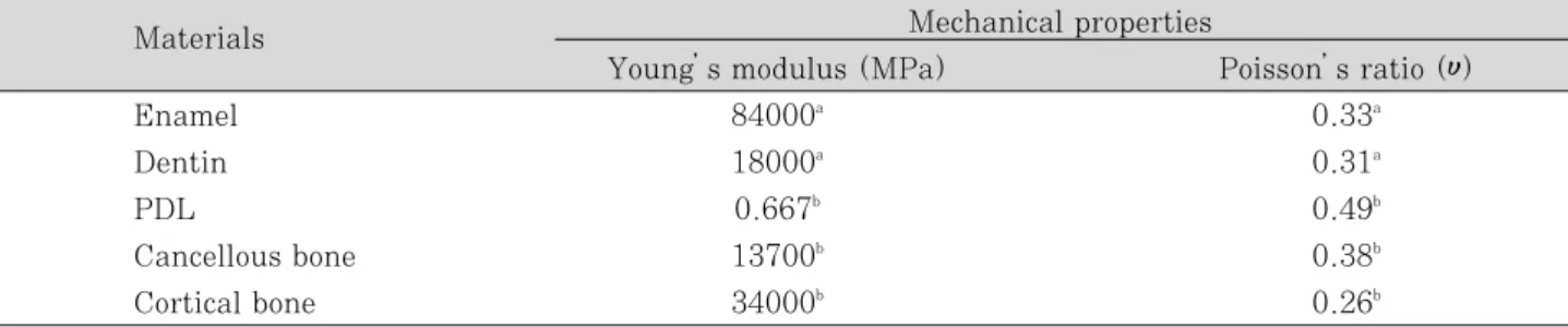
All the vital tissues were presumed linearly elastic, homogeneous and isotropic. The corre- sponding elastic properties such as Young’s mod- ulus and Poisson’s ratio were determined accord- ing to literature survey (Table 1). The periodontal ligament was assumed to be 0.3 ㎜ wide, and the dimensions of surrounding compact and cancellous bone were derived from standard texts. The alve- olar bone was also generated by growing the outer surface of the tooth model from 2 ㎜ below the cemento-enamel junction (CEJ)20,21). The pulp region was modeled as being hollow22). In these models, the outer surface of the alveolar bone model was fixed in order to prevent rigid body
motion for FEA.
The model was fixed on mesiodistal direction. In all loading cases, the base nodes of simulated alveolar bone were assumed fixed to prevent rigid body motion.
Experimental conditions and simulated groups
Loading conditions
A static load of 500 N was applied on a point load condition at buccal and palatal cusps.
Perpendicular load on the upper third of the palatal slope of the buccal cusp (Load A) and per- pendicular load on the upper third of the buccal slope of the palatal cusp (Load B) were used in this study (Figure 1).
Table 1.Mechanical properties of the tooth used in the study
Materials Mechanical properties
Young’s modulus (MPa) Poisson’s ratio (υ)
Enamel 84000a 0.33a
Dentin 18000a 0.31a
PDL 0.667b 0.49b
Cancellous bone 13700b 0.38b
Cortical bone 34000b 0.26b
a: Katona et al.23), b: Geramyet al.24)
Figure 1. Design of loading conditions on restored NCCL.
A B
Restorative materials and adhesive layer thick- ness
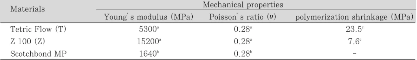
Notch shaped cavity was filled with either hybrid or flowable resin and each restoration was simulated with a adhesive layer thickness (40 ㎛) (Figure 3). The data of material properties such as elastic modulus, Poisson’s ratio and polymer- ization shrinkage were determined by literature review (Table 2). The Tetric Flow (Vivadent Ets., FL-9494-Schaan, Liechtenstein) and Z100 (3M Dental Products, St. Paul, MN, USA) were used as representatives of flowable and hybrid resin.
Dentin bonding system used in this study was Scotchbond Multi Purpose (3M Dental Products, St. Paul, MN, USA). The adhesive layer was made by mathematical shell element modeling and the conjunctions between materials were set as complete coupling.
Groups for simulation
The variables were loading condition (A or B) and restoration material (Tetric Flow; T or Z100;
Z). The tested groups were classified as 4 situa- tions by the restoration material (T or Z) and loading condition (A or B) with adhesive layer thickness (40 ㎛); T40A, T40B, Z40A, Z40B.
Stress analysis
After shear stress set to be zero, normal stress was expressed as S1, S2 and S3. And then, S1 was appointed as maximum principal stress and S3 as minimum principal stress. A graph was obtained based on the data of principal stresses at each node with load A or B.
The principal stresses in the lesion apex (that is internal line angle of cavity) and middle vertical wall were analyzed using ANSYS.
Table 2.Mechanical properties of the materials used in the study
Materials Mechanical properties
Young’s modulus (MPa) Poisson’s ratio (υ) polymerization shrinkage (MPa)
Tetric Flow (T) 5300a 0.28a 23.5c
Z 100 (Z) 15200a 0.28a 7.6c
Scotchbond MP 1640b 0.28b -
a: Katona et al.23), b: Le et al.25), c: Cornelis et al.26)
Figure 2. Simulated restoration of notch shaped NCCL.
(Left; buccal view, Right; proximal view).
The data of compressive strength and tensile strength of enamel and dentin are cited from the report of Litonjua et al.14)(Table 3).
Ⅲ. Results
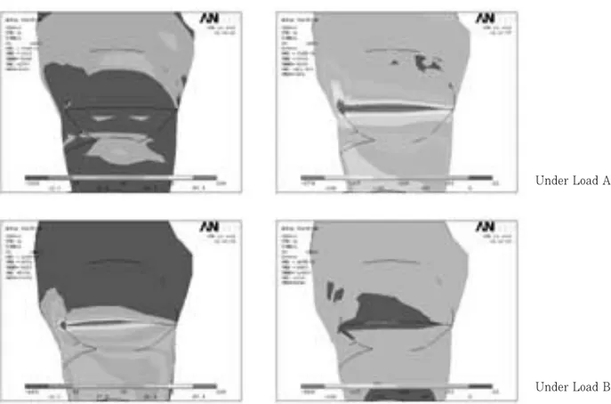
Principal stresses before restoration (Figures 3, 4 and Table 4)
Before restoration, the stresses were highly con- centrated at mesial CEJ and lesion apex (Figure 3).
The first peak stresses of tensile stress at all area of notch shaped NCCL were over the mechanical properties of teeth.
The peak compressive stress of 588.0 MPa was concentrated at mesial point angle (MP) of the lesion under load A and the peak tensile stress of 193.3 MPa was concentrated at MP under load B.
Figure 3. Principal stress highly concentrated at mesial CEJ and lesion apex under load A and B in unrestored cavity (Left; Maximal principal stress-tensile stress, Right; Minimal principal stress-compressive stress).
Table 3.Mechanical properties of teeth (MPa) Compressive strength of enamel 277 - 384 Compressive strength of dentin 249 - 347 Tensile strength of enamel 10 - 24 Tensile strength of dentin 32 - 103 Tensile strength of dentino-enamel
junction 52
*: Litonjua et al.14)
Under Load A
Under Load B
Principal stresses after restoration
After restoration using Z100 and Tetric Flow, there was significant stress relief, but its magni- tude was different for each area and each treat- ment (Figure 5).
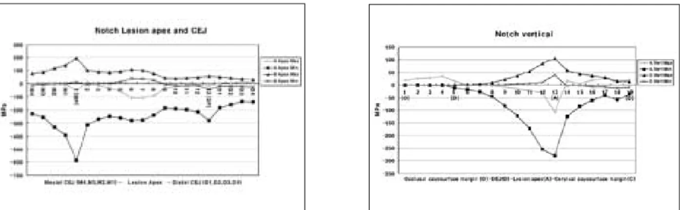
Lesion apex and CEJ (Figure 6 and Table 5)
On lesion apex and CEJ, the peak compressive stress of 299.1 MPa was concentrated at M1 point under load A by restoration using T40. By restoration using Z100, the relatively low com- pressive stress of 233 MPa was concentrated at M1 point.
The peak tensile stress of 93.2 MPa was con- centrated at M1 point under load B by restoration
using T40. By restoration using Z100, the rela- tively low tensile stress of 68 MPa was concen- trated at M1 point.
Middle vertical cavity wall (Figure 7, Table 6)
On middle cavity wall, the peak compressive stress of 70.8 MPa was concentrated at cervical cavosurface margin under load A by restoration using Z40. By restoration using T40, the relative- ly low compressive stress of 57.4 MPa was con- centrated at lesion apex.
The peak tensile stress of 39.9 MPa was con- centrated at the node of 17 under load B by restoration using Z40. By restoration using T40, the relatively low tensile stress of 31.7 MPa was concentrated at the node of 15.
Figure 4. The principal stress distribution on lesion apex and middle vertical wall before restoration under load A and B. (MP: Mesial point angle, DP: Distal point angle, O: Occlusal cavosurface margin, D: DEJ, A: Lesion apex, C: Cervical cavosurface margin).
Table 4.Peak stresses of each area before restoration
Load A Load B
1stPeak 2ndPeak 1stPeak 2ndPeak
MPa location MPa location MPa location MPa Location
Apex / CEJ Max 12.4* 2 10.9* D3 193.3* 1 (MP) 104.3* 6
Min -588.0* 1 (MP) -279.8* DP -44.5 DP NS NS
Vertical Max 33.7* 4 25.5 17 104.3* 13 (A) NS NS
Min -280.4* 13 (A) -58.8 18 -12.5 18 (C) NS NS
*: Excessive stresses over the failure range
A: Lesion apex, C: Cervical cavosurface margin, MP: Mesial point angle, DP: Distal point angle, NS: not sig- nificant
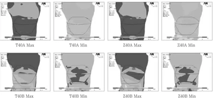
Figure 6. The principal stress distribution on lesion apex and CEJ after restoration under load A and B.
T40A Max T40A Min Z40A Max Z40A Min
T40B Max T40B Min Z40B Max Z40B Min
Table 5.Peak stresses of lesion apex and CEJ
Load A Load B
1stPeak 2ndPeak 1stPeak 2ndPeak
MPa location MPa location MPa location MPa Location
T40 Max 16.5* D4 NS NS 93.2* M1 41.8* D1
Min -299.1* M1 -128.9 D1 -27.7 D4 -18.8 M4
Z40 Max 18.6* D4 NS NS 68.0* M1 38.0* D1
Min -232.8 M1 -94.0 D1 -28.8 D4 -22.0 M4
*: Excessive stresses over the failure range
Figure 5. Principal stress distribution after each restoration (Max; Maximal principal stress-tensile stress, Min;
Minimal principal stress-compressive stress).
Ⅳ. Discussion
The notch shaped lesion has a sharp line angle at the apex of the lesion, and the location with the highest stress concentration corresponded to sharpest geometric discontinuity. Therefore, it is suggested that the severity of geometric disconti- nuity of NCCL plays a significant role in the development of internal stress in tooth1-5). Since cervical lesions act as stress concentrators, NCCL, especially abfraction lesions, will extend if not restored. Grippo also suggested that, if the lesion is left unrestored, the stress concentration caused by the cervical lesion would facilitate fur-
ther deterioration of tooth structure. He also hypothesized that restoration decrease the con- centration of stress and further progress of the lesion7). But Osbome-Smith et al.27)concluded that the restoration of NCCL with resin-modified glass ionomer or composite resin did not result in a sta- tistically significant increase in the fracture resis- tance.
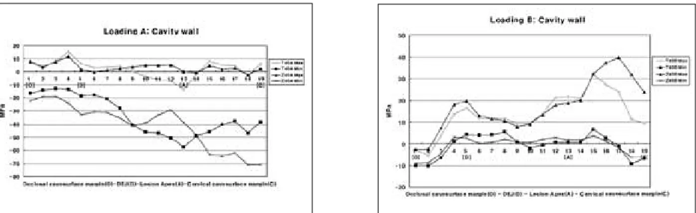
Kuroe et al.28)reported that, regardless of lesion shape, higher stress was developed at the apex of an unrestored cervical lesion than at any other portion of the tooth when the cusp located above the lesion was loaded. In this study, the stress distributions were analyzed with 3D FEA with Table 6.Peak stresses of vertical cavity wall
Load A Load B
1stPeak 2ndPeak 1stPeak 2ndPeak
MPa location MPa location MPa location MPa Location
T40 Max 14.9* 4 8.1 15 31.7 15 16.6 5 (D)
Min -57.4 13 (A) -46.7 18 -9.8 1 (O) -9.0 19 (C)
Z40 Max 11.7* 4 5.2 12 39.9 17 19.8 5 (D)
Min -70.8 19 (C) -40.9 9 -8.9 1 (O) -5.9 19 (C)
*: Excessive stresses over the failure range O: Occlusal cavosurface margin
D: DEJ of occlusal wall A: Lesion apex
C: Cervical cavosurface margin
Figure 7. The middle vertical distribution of principal stress on cavity wall after restoration under load A (upper) and B (lower).
the variables of loading condition, the thickness of adhesive layer and restorative material. According to stress analysis, mesial CEJ corner and lesion apex showed high stress distribution before restoration. It is expected that unrestored notch shaped NCCL would be extended around the mesial and distal corner area of all cavosurface margin by continuous failure with excessive com- pressive or tensile stress under load A or load B, respectively. Because of the anatomical mesiodis- tal asymmetry, higher stresses were concentrated at mesial point angle than distal.
Other than wear resistance and color stability, the most important characteristic of restorative material is the modulus of elasticity or stiffness of the material. This is important for the masticato- ry stresses are transferred through the cusp and concentrated at the cervical region. It is recom- mended, therefore, that composite resin with a low modulus of elasticity be used. With this type of resin, much of the transferred energy is absorbed by the restoration rather than transmit- ted to the dentin-restoration interface29).
In a study of various resin-based restoratives, Yaman et al.30) concluded that if the restoration material had larger Young’s modulus, less stress was developed in restored tooth. Similar to the results of this study, Z100 was found to be supe- rior to the other materials concerned. And they revealed that by increasing load size or load angle or cavity size, there was increase in stress distri- bution30). On the other hand, there was an inves- tigation that no differences were found between a microfilled and a hybrid resin, although two materials have widely different moduli of elastici- ty31). As the results of this study, the principal stresses were remarkably reduced at highly stress concentrated area such as lesion apex or CEJ with restoration using Z100, while they were reduced on the other areas with restoration using Tetric Flow. This was the same results by Yaman30)that restoration using Z100 worked as a strut to prevent stress concentration of the lesion.
After restoration, highly stress concentrated area migrated from mesial point angle to mesial
son of progression of the lesion to CEJ area, espe- cially in Tetric Flow restoration.
As the results of this study, compressive stress- es were created under load A and tensile stresses under load B in the point of principal stresses.
The peak stresses of both principal stresses were decreased after restoration, but high stress con- centration still remained around mesial point angle. This compressive stresses over the failure range under load A could be decreased under the limit after restoration, but tensile stresses over the limit range under load B were still remained on various areas. These mean that the tensile stresses may be the major factor to jeopardize the restoration durability and to promote the lesion progression. Therefore some clinicians28,32,33)recom- mended that occlusal adjustment be considered as a treatment option, in addition to restoration, for abfraction lesions. Occlusal adjustments may reduce stress concentration at the cervical lesion, but they may jeopardize equilibrium of the occlu- sion if careful consideration for the entire occlu- sion is omitted. And they are also difficult to do with confirm on which side of occlusion concerning tensile or compressive is modified. Therefore the restoration of NCCL is first concern and then the selection of restorative material may have influ- ence on the prognosis of the lesion and restora- tion.
In future, it is recommended to evaluate the restoration of NCCL using not only a single mate- rial but also two or more materials, based on the relation of restorative material’s mechanical properties and regional differences of stresses in the lesion. And the selection of the mechanical properties of the restorative material for long- term clinical success is the question remaining to be answered.
Ⅴ. Conclusion
1. Under loading A, compressive stress is created in the unrestored and restored cavity. Under loading B, tensile stress is created. And the peak stress concentration is seen at near
condition.
2. Compared to the unrestored cavity, the princi- pal stresses at the CEJ and line angle of the cavity were more reduced in the restored cavity on both load condition.
3. In teeth restored with hybrid composite, the principal stresses at the CEJ and line angle of the cavity were more reduced than flowable resin.
References
1. Levitch LC, Bader JD, Shugars DA, Heymann HO.
Non-carious cervical lesion. J Dent 22:195-207, 1994.
2. Grippo JO, Simring M, Schreiner S. Attrition, abra- sion, corrosion and abfration revisited - A new per- spective on tooth surface lesions. J Am Dent Assoc 135:1109-1118, 2004.
3. Grippo JO. Abfractions: A new classification of hard tissue lesions of tooth. J Esthet Dent 3(1):14-19, 1991.
4. Rees JS. A review of the Biomechanics of abfraction.
Eur J Prosthdont Restor Dent 7(4):139-144, 1993.
5. Aw TC, Lepe X, Johnson GH, Mancl L. Characteristics of non-carious cervical lesion. J Am Dent Assoc 133:725-733, 2002.
6. Bader JD, Levich LC, Shugars DA, Heymann HO, Mcclure F. How dentists classified & treated non-cari- ous cervical lesions. J Am Dent Assoc 124:46-54, 1993.
7. Grippo JO. Non-carious cervical lesions: The decision to ignore or restore. J Esthet Dent 4:55-64, 1992.
8. Blunck U. Improving cervical restorations: A Review of Materials and Techniques. J Adhes Dent 3:33-44, 2001.
9. Kemp-Scholte CM, Davidson CL. Complete marginal seal of class V resin composite restorations effected by increased flexibility.J Dent Res 69:1240-1243, 1990.
10. Kemp-Scholte CM, Davidson CL. Marginal integrity related to bond strength and strain capacity of compos- ite resin restorative system. J Prosthet Dent 64:658- 664, 1990.
11. Van Meerbeek B, Peumans M, Gladys S, Braem M, Lambrechts P, Vanherle G. Three-year clinical effec- tiveness of four total-etch dentinal adhesive systems in cervical lesions. Quintessence Int 27:775-784, 1996.
12. Ausiello P, Apicella A, Davidson CL. Effect of adhesive layer properties on stress distribution in composite restorations-a 3D finite element analysis. Dent Mater 18:295-303, 2002.
13. Powell LV, Johnson GH, Gordon GE. Factors associat- ed with clinical success of cervical abrasion/erosion restorations. Oper Dent 20:7-13, 1995.
14. Litonjua LA, Andreana S, Patra AK, Cohen RE. An assessment of stress analyses in the theory of abfrac- tion. Biomed Mater Eng 14:311-321, 2004.
15. Rees JS. The role of cuspal flexure in the development of abfraction lesions: a finite element study. Eur J
Oral Sci 106:1028-1032, 1998.
16. Tanaka M, Naito T, Yokota M, Kohno M. Finite ele- ment analysis of the possible mechanism of cervical lesion formation by occlusal force. J Oral Rehabil 30:60-67, 2003.
17. Rees JS, Hammadeh M. Undermining of enamel as a mechanism of abfraction lesion formation: a finite ele- ment study. Eur J Oral Sci 112:347-352, 2004.
18. Son YH, Cho BH, Um CM. Finite element stress analysis of class V composite resin restoration subject- ed to cavity forms and placement methods. J Kor Acad Cons Dent 25(1):91-108, 2000.
19. Um CM, Kwon HC, Son HH, Cho BH, Rim YI. Finite element analysis of stress distribution according to cavity design of class V composite resin filling. J Kor Acad Cons Dent 25(1):67-74, 1999.
20. Lindehe J, Karring T. Textbook of Clinical Periodontology. 2nd edition, Munksgaard, Copenhagen, p19-69, 1989.
21. Schroeder HE, Page RC. Periodontal Diseases. 2nd edition, Lea & Fabiger, Philadelphia, p3-52, 1990.
22. Rubin C, Krishnamurthy N, Capilouto E, Yi H. Stress analysis of the human tooth using a three-dimensional finite element model. J Dent Res 62:82-86, 1983.
23. Katona TR, Winkler MM. Stress analysis of a bulk- filled class V light-cured composite restoration. J Dent Res 73(8):1470-1477, 1994.
24. Geramy A, Sharafoddin F. Abfraction: 3D analysis by means of the finite element method. Quintessence Int 34(7):526-533, 2003
25. Le SY, Chiang HC, Huang HM, Shih YH, Chen HC, Dong DR, Lin CT. Thermo-debonding mechanisms in dentin bonding systems using finite element analysis.
Biomaterials 22(2):113-123, 2001.
26. Kleverlaan CJ, Feilzer AJ. Polymerization shrinkage and contraction stress of dental resin composite. Dent Mater article in press, 2005.
27. Osbome-Smith KL, Burke FJT, Mc Farlane T, Wilson NHF. Effect of restored and unrestored non-carious cervical lesions on the fracture resistance of previously restored maxillary premolar teeth. J Dent 26:427-433, 1998.
28. Kuroe T, Itoh H, Caputo AA, Konuma M.
Biomechanics of cervical tooth structure lesions and their restoration. Quintessence Int 31(4):267-273, 2000.
29. Leinfelder KF. Restoration of abfracted lesions.
Compend Contin Educ Dent 15:1396-1400, 1994.
30. Yaman SD, Sahin M, Aydin C. Finite element analysis of strength characteristics of various resin based restorative material in Class V cavities. J Oral Rehabil 30:630-641, 2003.
31. Browning WD, Bracket WW, Gilpatrick RO. Retention of microfilled and hybrid resin-based composite in non- carious class 5 lesions: A double-blind, randomized clinical trial. Oper Dent 24:26-30, 1999.
32. Grippo JO, Simring M. Dental “erosion”revisited. J Am Dent Assoc 126:619-630, 1995.
33. Lee WC, Eakle WS. Stress-induced cervical lesions:
Review of advances in the past 10 years. J Prosthet Dent 75:487-494, 1996.
복합레진 수복물이 쐐기형 비우식성 치경부 병소의 응력 분포에 미치는 영향에 관한 3차원 유한요소법적 연구
이채경1∙박정길1∙김현철1∙우성관2∙김광훈2∙손 권2∙허 복1*
1부산대학교 치과대학 치과보존학교실, 2부산대학교 공과대학 기계설계공학과
이 연구의 목적은 쐐기형 비우식성 5급와동을 복합레진으로 수복하기 전, 후에 과도한 교합력에 의한 응력분포 변화를 비교연구하기 위함이었다.
발치된 상악 제2소구치를 이용하여 쐐기형 비우식성 치경부병소를 가진 3차원 유한요소모형을 제작한 후 탄성계 수가 서로 다른 혼합형 복합레진과 흐름성 복합레진으로 각각 충전하고 이때의 상아질 접착제의 두께는 40 ㎛로 하 였다. 협측교두와 설측교두에 500 N의 하중을 각각 가한 후 ANSYS 프로그램을 이용하여 주응력분석법으로 병소 의 심부와 와동 수직벽의 응력분포를 비교하여 다음과 같은 결과를 얻었다.
1. 협측교두에 하중이 가해지면 병소에 압축응력이 나타나고, 설측교두에 가해지면 인장응력이 나타난다. 두 가 지 하중에서 모두 병소의 근심 끝 부위와 인접한 백악법랑경계 그리고 병소의 심부에 응력이 집중되었다.
2. 응력의 집중을 보였던 병소의 근심부근과 심부는 수복 후 응력이 많이 감소하였으며 대신 다른 부위에서는 응 력이 약간 증가하였다.
3. 병소의 근심부위와 심부는 흐름형 복합레진으로 수복하였을 때 보다 혼합형 복합레진으로 수복하였을 때 응력 이 더 많이 감소하였다.
주요어: 쐐기형 와동, 5급와동수복, 응력분포, 유한요소분석, 혼합형복합레진, 흐름형 복합레진 국문초록