490 https://doi.org/10.9713/kcer.2017.55.4.490
PISSN 0304-128X, EISSN 2233-9558
Steady State Design for the Separation of Acetone-Chloroform Maximum Boiling Azeotrope Using Three Different Solvents
Manish Pokhrel, Asante Daniel Owusu, and Jungho Cho†
Department of Chemical Engineering, Kongju National University, 1223-24, Cheonan-daero, Seobuk-gu, Cheonan, Chungnam, 31080, Korea
(Received 26 October 2016; Received in revised form 30 March 2017; accepted 31 March 2017)
Abstract − We have designed an extractive distillation for separating maximum boiling azeotrope of acetone-chloro- form system. PRO/II 9.4 was used to simulate the overall process. The VLE data adopted from Dortmund data bank was regressed to obtain a new set of binary interaction parameters. Three different entrainers were used for the separation process--dimethyl sulfoxide (DMSO), ethylene glycol (EG) and benzene--to test their viability for the acetone-chloro- form system. Thermodynamic feasibility analysis was done through ternary map diagrams. Two different thermody- namic models, NRTL and UNIQUAC, were explored for the study of overall process.
Key words: Extractive distillation, Maximum boiling azeotrope, Relative volatility, Residue curve map, Distillation boundary
1. Introduction
The distillation process is based on the difference in the volatil- ity of the components to be separated. However, for mixtures where azeotropes are present, conventional distillation have shown to be unable to effect the separation desired [1].
Acetone-chloroform mixture is a typical example of a system with established negative deviation from ideal solution behavior.
This mixture presents a negative azeotrope with a boiling point of 64.48 °C and an acetone mole fraction approximately equal to 0.3393 at 1 atm. For the mixture having close boiling points or forming azeotrope, conventional distillation cannot be used. Instead, spe- cial types of distillation processes should be applied. For instance, in azeotropic distillation a third component E is added to the feed.
A or B components become either a stable or unstable node on the residue curve in the relevant distillation region, thus being removable as product by either an indirect or a direct split, respectively [2].
The basis of extractive distillation (ED) is the increase of rela- tive volatility between the close-boiling components caused by introducing a selective solvent, which has stronger affinity with one type of the components in the mixture [3]. In this study, we con- trolled and optimized the distillation of acetone-chloroform system using three different entrainers which include DMSO, ethylene- glycol and benzene. Extractive distillation can be more energy effi- cient than azeotropic separation, where a liquid phase split is used to overcome distillation boundaries [4]. This is especially true when thermally integrated sequences are used [5]. It has been reported
that pressure swing distillation is unattractive for the separation of acetone-chloroform system since its composition is not sensitive to pressure changes [6].
2. Problem design and specification
In extractive distillation, the added component (solvent) modifies the relative volatility of the original components and causes the azeo- tropic point to disappear. In this study, the heavy boiling entrainers were used, thus have the highest boiling point amongst all other components and thereby coming out from the bottom of the solvent recovery column. ‘A well-designed system’ implies the lowest energy consumption for the system as well as least loss of the solvent, tak- ing into consideration the constraints imposed on the process. The process can be called a ‘well-designed system’ only if the functions
†To whom correspondence should be addressed.
E-mail: [email protected]
This is an Open-Access article distributed under the terms of the Creative Com- mons Attribution Non-Commercial License (http://creativecommons.org/licenses/by- nc/3.0) which permits unrestricted non-commercial use, distribution, and reproduc- tion in any medium, provided the original work is properly cited.
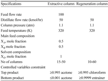
Table 1. Operating conditions and design specifications for the process optimization
Specifications Extractive column Regeneration column
Feed flow rate 100
Distillate flow rate (kmol/hr) 50 50
Column pressure (atm) 1.1 1.1
Feed temperature (K) 320 320
Main feed composition
XA, mole fraction 0.5
XB mole fraction 0.5
Solvent composition
XE, mole fraction 1
No of columns 15-50 10-60
Controlled variables constraint
Top product ≥0.995 acetone ≥0.995 chloroform Bottom product ≤0.001 acetone ≥0.9999 entrainer
like tray number, feed plate location of binary azeotropes and sol- vent are met. In addition, optimization of reflux ratio and the solvent flow rate is necessary. The operating conditions for the process opti- mization are listed in Table 1.
3. Solvent Selection
Solvent type has a dominant influence on the extraction process [7]. The effectiveness of an extractive distillation process largely depends on an efficient extractive solvent whose performance is often evaluated on the basis of its relative volatility, solubility power, boil- ing point and molecular weight [8]. The solvents were selected after studying the thermodynamic feasibility through the residue curve maps and volatility orders. One of the objectives of this study was also to investigate the performance of the solvents (ethylene glycol and benzene), which [9] regarded as failure candidates. Therefore, three solvents (DMSO, EG and benzene) were taken, all of which successfully passed the thermodynamic feasibility test conducted.
Homogeneous batch extractive distillation of acetone-chloroform mixture with a heavy boiling solvent is possible if there exists a resi- due curve connecting solvent to acetone or chloroform, following an increasing temperature direction inside the region where sol- vent is the most heavy boiling component of the mixture [8,10].
4. Thermodynamic Modeling
In this study, two different common thermodynamic packages, Non-random two-liquid model (NRTL) and UNIQUAC, were applied.
The VLE experimental data for acetone-chloroform [11], acetone- DMSO [12] chloroform-DMSO [13], acetone-benzene [14] and chloroform-benzene [15] were obtained from Dortmund data bank.
Regression was carried out to obtain a new set of binary interaction parameters as shown in Tables 2 and 3. However, for the acetone- chloroform-ethylene glycol (EG) system PRO/II inbuilt parameters were considered. The fitting of experimental data with NRTL and UNIQUAC models is shown in Figures 1 and 2.
The NRTL equation is given as:
(1)
where τij and Gji in Eq. (1) are the optimum binary interaction parameters that minimize deviations from experimental data. τij and Gji can be expressed as:
γi
ln
∑
j jiτ Gjixjk kiG xk
---
∑
Gjixj kGkjxk∑
---∑
j τij∑
k kxτkjGkjGkjx
k k
---
∑
⎝ – ⎠
⎜ ⎟
⎛ ⎞
+
=
Table 2. UNIQUAC binary interaction parameters for acetone-chloroform-DMSO/Benzene systems
Ci Acetone Acetone Chloroform Acetone Chloroform
Cj chloroform DMSO DMSO Benzene Benzene
aij −122.8 84.136 −208 −116.7 −127.6
bij 59.071 −5.041 −299.3 −186.3 127.89
Table 3. NRTL binary interaction parameters for acetone chloroform-DMSO and acetone-chloroform-benzene systems
Ci Acetone Acetone Chloroform Acetone Chloroform
Cj chloroform DMSO DMSO Benzene Benzene
aij −8.848 1.756 0.333 0.312 1.825
bij 2529 365.2 42.16 −56.42 573.5
aji 9.972 0.209 0.904 0.653 −2.244
bji −3126 30.47 −191.9 −93.76 −753.8
cij 0.105 0.872 0.434 0.900 −0.050
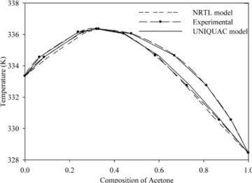
Fig. 1. Fitting of experimental data in T-XY plot for acetone-chloroform system using NRTL and UNIQUAC models.
Fig. 2. Fitting of experimental data in XY plot for acetone-chloro- form system using NRTL and UNIQUAC models.
(2)
(3) The UNIQUAC equation is given as:
(4) The first is an entropic term quantifying the deviation from ideal solubility as a result of differences in molecule shape. The latter is an enthalpic correction caused by the change in interacting forces between different molecules upon mixing.
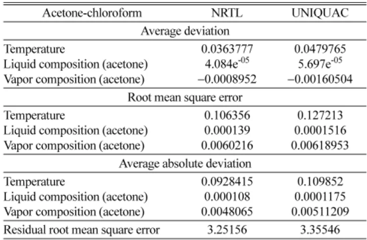
Both of the models somehow fit the curve equally. Deviation of experimental values from the regressed values was explored as dis- played in Table 4.
From Table 4 both NRTL and UNIQUAC models can be used to describe the system since the deviations from their mean values are quite small.
The ternary map in Figure 3 is divided into two regions by the distillation curve. Both acetone and chloroform are unstable nodes.
The distillation boundary is created because there are two unstable nodes instead of one. The azeotrope is a saddle point and DMSO serves as stable node. The residue curve map moves towards higher temperature, i.e., towards DMSO. As long as both the distillate and bottom product are in the same region, separation is feasible. The bottom product B1, however, seems to lie outside the distillation boundary. Due to curve nature of the distillation boundary, separa- tion is possible.
Upon substituting the in-built binary interaction parameters with the new set, the azeotropic point between acetone-chloroform shifts from 66.99oC to 67.89oC at 1.1 atm pressure.
Figure 4 describes the process flow diagram for the separation of acetone-chloroform-solvent system in which the azeotropic mixture and the solvent are fed to the first column wherein the acetone (low- est boiling component) goes towards the rectifying section. Mean- while, chloroform alongside the solvent come towards the stripping section [16]. The bottom stream is then fed to second column to
recover the solvent from the bottom as chloroform exists from the top. A small amount of make-up stream is fed to the system to account for the solvent loss.
5. Optimization
The columns T1 and T2 have many degrees of freedom [5]. Aside from the number of trays, feed- and solvent-tray locations, mini- mum reflux ratio and minimum solvent to feed ratio are needed for the optimization of the process. In most distillation columns the major operating cost is reboiler energy consumption. Provided the top and bottom compositions of the columns, different case studies have been performed to minimize the re-boiler heat duty. For the purpose of optimization study, Radfrac, a rigorous model for distil- lation columns, was selected.
The problem was formulated as:
Jmin = Qr/D
where Qr is the total energy consumption and D is the distillate.
τji aij bij ---T cij
T2
--- dijlnT eijT f+ ijTlnT
+ + + +
=
Gji=exp(–αjiτji)
γi
ln =lnγic+lnγiR
Table 4. Deviation of temperature and liquid and vapor composition of acetone from their mean value using NRTL and UNIQUAC method
Acetone-chloroform NRTL UNIQUAC
Average deviation Temperature
Liquid composition (acetone) Vapor composition (acetone)
0.0363777 4.084e-05
−0.0008952
0.0479765 5.697e-05
−0.00160504 Root mean square error
Temperature
Liquid composition (acetone) Vapor composition (acetone)
0.106356 0.000139 0.0060216
0.127213 0.0001516 0.00618953 Average absolute deviation
Temperature
Liquid composition (acetone) Vapor composition (acetone)
0.0928415 0.000108 0.0048065
0.109852 0.0001175 0.00511209 Residual root mean square error 3.25156 3.35546
Fig. 3. Ternary diagram for Acetone-Chloroform-DMSO system using NRTL.
Fig. 4. Process flow diagram distillation of acetone-chloroform-DMSO/
Benzene/EG.
5-1. Number of trays
The numbers of trays were varied manually, and for each run the re-boiler heat duty was noted to obtain the Figures 5, 6 and 7 for the different solvents. The optimum numbers of trays were taken for the simulation.
5-2. Solvent flow rate and reflux ratio
The effect of solvent flow rate at constant reflux ratio and the com- bined effect of solvent flow rate and reflux ratio on the amount of chloroform on the distillate stream for acetone-chloroform-DMSO system are shown in Figures 8 and 9, respectively, using NRTL method.
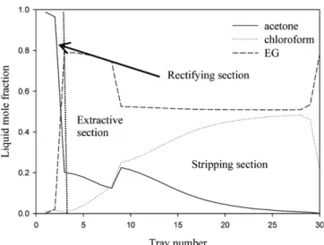
The liquid composition profile in the extractive column and the regeneration column with EG are given in Figures 10 and 11.
6. Results and discussion
A study on the separation of the acetone-chloroform system was made, using three different entrainers, among which benzene was found to be an improper selection as it could not meet the design specifications. In case of benzene, despite consuming high heat duty yielded only 98.7 mol% of chloroform. Note that, unlike said by [9], EG has proved to be an attractive solvent for the acetone-chloroform system which has the potential to separate the azeotrope as dis- played in Table 5. Shen [2] made a similar conclusion which sup- Fig. 5. No. of trays Vs re-boiler heat duty for acetone-chloroform-
DMSO.
Fig. 6. No. of trays Vs re-boiler heat duty for acetone-chloroform-EG.
Fig. 7. No. of trays Vs re-boiler heat duty for acetone- chloroform- benzene.
Fig. 8. Effect of solvent flow rate on the re-boiler heat duty at con- stant reflux ratio for the acetone-chloroform-dmso system.
Fig. 9. Effect of solvent flow rate and reflux ratio on the amount of chloroform on the distillate stream.
ports this study. Furthermore, the optimum solvent flow rate as depicted by [9] was 164.4 Kmol/hr for the DMSO system which has, in this study, been further minimized to 135.286 Kmol/hr using UNI- QUAC model and 77.47 Kmol/hr using NRTL model. Therefore, the total re-boiler heat duty of 2.259M*kcal/hr (2.62 MW)as illustrated by [9] has been reduced to1.7756 M*kcal/hr thereby minimizing the re-boiler heat duty by 21.39%.
During the optimization process, there was a non-monotonic effect on each manipulated variable as acknowledged by many authors [2,17]. DMSO and EG, both are competitive entrainers as they can easily cope with our target and do not demand much energy like benzene.
Acetone-chloroform-DMSO demands less solvent flow rate and number of trays than acetone-chloroform-EG system, as depicted in Table 5. Under the same operating conditions and design specifica- tions, acetone-chloroform with DMSO solvent consumes less energy than with EG solvent. Therefore, DMSO is supposed to be a better solvent for the separation of acetone and chloroform system. This result, however, is inconsistent with the conclusion set by Shen [2]
in which EG was considered a better option.
From the fitting of experimental data in TXY and XY plot from Figures 1 and 2, and from Table 4 in which NRTL model has lesser deviation and therefore best fits the system than UNIQUAC model.
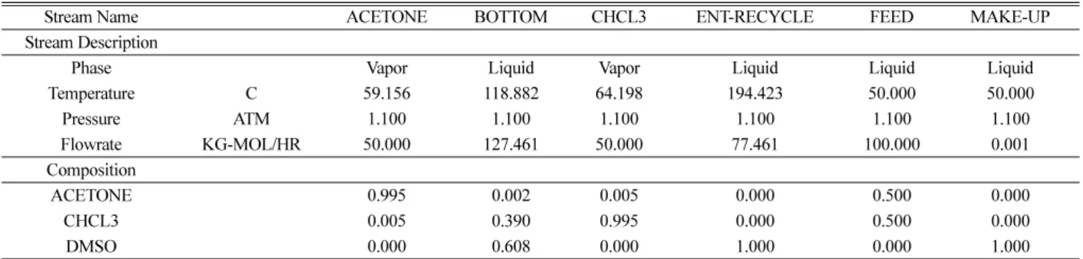
The optimized variables using NRTL model for the overall process are listed in Table 6. From Table 6, DMSO proves to be the most promising solvent for the azeotropic system followed by EG, which is also an effective solvent, whereas benzene fails to meet the design specification and hence can be discarded. The stream property table for acetone-chloroform-DMSO is illustrated in Table 7.
For all the processes, the cooling water and steam consumption Fig. 10. Liquid mole fraction Vs tray number of the 1st column.
Fig. 11. Liquid mole fraction Vs tray number of the 2nd c.
Table 5. Comparison of different parameters on the basis of UNIQUAC and NRTL models
Reflux ratio Solvent flow rate (Kmol/hr) Condenser heat duty (M*kcal/hr) Re-boiler heat duty (M*kcal/hr) UNIQUAC
1st column 2nd column 1st column 2nd column 1st column 2nd column
DMSO 0.62 0.70 135.29 0.22 0.25 1.11 0.85
EG 0.37 1.98 301.62 0.17 0.69 1.70 1.85
Benzene 8.75 15.8 310.60 3.42 6.02 3.81 6.03
NRTL
DMSO 0.92 0.80 77.47 0.32 0.28 0.99 0.79
EG 0.37 0.37 180.73 0.13 0.13 1.13 1.13
Benzene 15.6 25.1 236.85 4.41 9.34 4.72 9.34
Table 6. Optimized variables for the overall process
Reflux ratio Solvent flow rate (kmol/hr) Condenser heat duty (M*kcal/hr) Re-boiler heat duty (M*kcal/hr) 1st column 2nd column 1st column 2nd column 1st column 2nd column
DMSO 0.92 0.8 77.47 0.32 0.28 0.99 0.79
EG 0.37 0.37 180.73 0.13 0.13 1.13 1.13
Benzene 15.5 25.1 236.85 4.41 9.34 4.72 9.34
Feed tray location Solvent tray location Feed location to 2nd column No of trays 1st column 2nd column
DMSO 12 4 6 22 10
EG 3 9 4 30 10
Benzene 18 14 11 50 60
was also evaluated. The cooling water was supplied at 32oC and withdrawn at 40oC, while steam was supplied at 145oC. The con- sumption of cooling water and steam by the overall process has been listed in Table 8.
7. Conclusion
A a systematic process for an extractive distillation for the sepa- ration of acetone-chloroform (maximum boiling) azeotrope using three heavy solvents was done. The conceptual design using ternary diagram was illustrated for acetone-chloroform-DMSO system.
The VLE data upon regression were used for the simulation pro- cess except for the system with EG in which only a case study was performed. From the above discussion, we concluded that DMSO is the most promising solvent among DMSO, EG and benzene sol- vents, that can be used for the separation of acetone-chloroform system.
Acknowledgment
This research was supported by a grant from LNG Plant R&D Center founded by Ministry of Land, Transportation and Maritime affairs (MLTM) of the Korean government.
Notation
VLE : Vapor liquid equilibrium NRTL : Nonrandom two liquid UNIQUAC : Universal quasichemical DMSO : Dimethyl sulfoxide EG : Ethylene glycol Qr : Total energy consumption D : Distillate
Ci : Component i
Cj : Component j
aij/aj : Non-temperature dependent energy parameters between components i and j or j and i [cal/gmol]
bij/bji : Temperature dependent energy parameter between components i and j or j and i [cal/gmol-K]
cij : NRTL non-randomness constant for binary interaction
References
1. M. F. de Figueirêdo, B. P. Guedes, J. M. M. de Araújo, L. G. S.
Vasconcelos, and R. P. Brito, “Optimal Design of Extractive Distilla- tion Columns-A Systematic Procedure Using a Process Simula- tor,” Chem. Eng. Res. Des., 89(3), 341-346(2011).
2. W. Shen, L. Dong, S. Wei, and J. Li, “Systematic Design of An Extractive Distillation for Maximum-boiling Azeotropes with Heavy Entrainers,” AIChE…, 2015.
3. F.-M. Lee, “Extractive Distillation,” 2000.
4. Z. Lei, C. Li, and B. Chen, “Extractive Distillation: A Review,”
Sep. Purif. Rev., 32(2), 121-213(2003).
5. J. Knapp and M. Doherty, “Thermal Integration of Homogeneous Azeotropic Distillation Sequences,” AIChE J., 36(7), 969-984 (1990).
6. W. L. Luyben, “Control of the Maximum-Boiling Acetone/Chloro- form Azeotropic Distillation System,” Ind. Eng. Chem. Res., 47(16), 6140-6149(2008).
7. P. Ramakul, M. Hronec, and U. Pancharoen, “Purification of 2- mercaptobenzothiazole by Solvent Extraction,” Korean J. Chem.
Eng., 24(2), 282-287 (2007).
8. S. Kossack, K. Kraemer, R. Gani, and W. Marquardt, “A System- atic Synthesis Framework for Extractive Distillation Processes,”
Chem. Eng. Res. Des., 86, 781-792(2008).
9. W. L. Luyben, “Comparison of Extractive Distillation and Pres- sure-swing Distillation for Acetone/chloroform Separation,” Com- put. Chem. Eng., 50, 1-7(2013).
10. I. Rodriguez-Donis, V. Gerbaud, and X. Joulia, “Thermodynamic Insights on the Feasibility of Homogeneous Batch Extractive Distillation. 4. Azeotropic Mixtures with Intermediate Boiling Table 7. Stream property table for acetone-chloroform-DMSO
Stream Name ACETONE BOTTOM CHCL3 ENT-RECYCLE FEED MAKE-UP
Stream Description
Phase Vapor Liquid Vapor Liquid Liquid Liquid
Temperature C 59.156 118.882 64.198 194.423 50.000 50.000
Pressure ATM 1.100 1.100 1.100 1.100 1.100 1.100
Flowrate KG-MOL/HR 50.000 127.461 50.000 77.461 100.000 0.001
Composition
ACETONE 0.995 0.002 0.005 0.000 0.500 0.000
CHCL3 0.005 0.390 0.995 0.000 0.500 0.000
DMSO 0.000 0.608 0.000 1.000 0.000 1.000
Table 8. Consumption of cooling water and steam
DMSO EG Benzene
1st column 2nd column 1st column 2nd column 1st column 2nd column
Cooling water (Kmol//hr) 2,257 1,777 905 6,177 23,764 41,593
Steam (Kmol/hr) 108 83.21 123 200 419 655
Entrainer,” Ind. Eng. Chem. Res., 51(18), 6489-6501(2012).
11. L. S. Kudryavtseva, M. P. Z. P. K. Susarev, and Leningard, “Liq- uid-vapor Equilibrium in Chloroform-hexane and Acetone-chlo- roform Systems,”36, 1231-1237(1963).
12. Y. Sassa, “Isothermal Vapor-Liquid Equilibrium Data of DMSO Solutions by Total Pressure Method. DMSO-Acetone, DMSO- Tetrahydrofuran, and DMSO-Ethyl Acetate Systems,”19(1), 44- 48(1974).
13. R. Philippe, C. Jambon, and P. Clechet, “Thermodynamic Prop- erties of Dimethylsulfoxide + Halomethane Mixtures II. Vapour
Pressures and Excess Thermodynamic Functions,” J. Chem. Ther- modyn., 5(3), 431-444(1973).
14. S. F. Brown I., “Dortmund Data Bank,” J. Chem, 10, 423(1957).
15. International Critcal Tables. MC Graw Hill, 1928.
16. P. Langston, N. Hilal, S. Shingfield, and S. Webb, “Simulation and Optimisation of Extractive Distillation with Water as Solvent,”
Chem. Eng. Process. Process Intensif., 44(3), 345-351(2005).
17. Z. Lei, C. Li, and B. Chen, “Extractive Distillation: A Review,”
Sep. Purif. Rev., 32, 121-213(2003).