J. Sensor Sci. & Tech. Vol. 23, No. 4, 2014 234 Journal of Sensor Science and Technology
Vol. 23, No. 4 (2014) pp. 234-237 http://dx.doi.org/10.5369/JSST.2014.23.4.234 pISSN 1225-5475/eISSN 2093-7563
Thick Graphene Embedded Metal Heat Spreader with Enhanced Thermal Conductivity
Minsoo Park
+and Kukjin Chun
Abstract
In this paper, a copper foil -thick grapheme (thin graphite sheet)-copper foil structure is reported to achieve mechanically strong and high thermal conductive layer suitable for heat spreading components. Since graphene provides much higher thermal conductivity than copper, thick graphene embedded copper layer can achieve higher effective thermal conductivity which is pro- portional to graphene/copper thickness ratio. Since copper is nonreactive with carbon material which is graphene, chromium is used as adhesion layer to achieve copper- thick graphene-copper bonding for graphene embedded copper layer. Both sides of thick graphene were coated with chromium as an adhesion layer followed by copper by sputtering. The copper foil was bonded to sputtered copper layer on thick graphene. Angstrom's method was used to measure the thermal conductivity of fab- ricated copper- thick graphene-copper structure. The thermal conductivity of the copper- thick graphene -copper structures is measured as 686 W/m·K which is 1.6 times higher than thermal conductivity of pure copper.
Keywords: Thermal management, Thermal conductivity, Heat spreader, Thick graphene, Graphite sheet
1. INTRODUCTION
These days, mobile devices, such as smartphone, digital camera and portable gaming device, are getting lots of popularity because of their computational ability and mobility. Especially, smartphone is not traditional communication device. It is a handheld device that will be enable information collection, processing and distribution. Typical features are web surfing, real- time online gaming, video conferencing, HD video and GPS function. Additionally these features can be used at the same time.
However size of smartphone is getting smaller, especially in thickness. The result is increased power consumption leading to devices getting more heat [1,2].
Since the temperature in smartphone becomes higher, thermal management of the smartphone is more crucial for life time and stable operation. For heat dissipation of smartphone, there are 2 ways for heat dissipation, active and passive thermal solution. Active thermal solution, like using fans, is
not appropriate for small device, such as smartphone. So, passive thermal solution is essential for heat dissipation of the smartphone.
Heat spreader is one of the passive thermal solutions. Heat spreader which has good thermal conductivity becomes essential. The thermal conductivity is the most important characteristic for heat dissipation and thin nano layer like thick graphene is one of the promising materials due to its superb properties. However, graphene is known to be flaked off and is not good for adhesion. Graphene can be formed as multilayer with high thermal conductivity metals. In this way, Graphene could have strong mechanical property and better thermal conductivity than pure metal.
There are previous studies to enhance thermal conductivity.
Metal matrix composite is one way to enhance the thermal conductivity. In [3] the author reported diamond/metal composite. Thermal conductivity of diamond/copper composite is enhanced to 900 W/m·K prepared by high- pressure, high-temperature under 1027~1827
oC and 2-8 GPA using 70% (volume fraction) diamond. C/Al metal matrix composite is widespread application, but is limited by manufacturing problems, which is derived from the reactivity between carbon and liquid aluminum [3].
This paper presents the results of thermal simulation and fabrication of metal-thick graphene-metal structure for enhancement thermal conductivity.
School of Electrical Engineering, Seoul National University
SoEECS 301-1014, Seoul National University, 599 Gwanangno, Gwanak-gu, Seoul 151-744, Korea
+
Corresponding author: [email protected]
(Received: Jul. 1, 2014, Revised: Ju1. 21, 2014, Accepted: Jul. 24, 2014)
This is an Open Access article distributed under the terms of the Creative Commons Attribution Non-Commercial License(http://creativecommons.org/
licenses/bync/3.0) which permits unrestricted non-commercial use, distribution,
and reproduction in any medium, provided the original work is properly cited.
Minsoo Park and Kukjin Chun
235 J. Sensor Sci. & Tech. Vol. 23, No. 4, 2014
2. SIMULATION
2.1 Effective Thermal Conductivity
Fig. 1 shows proposed thick graphene embedded metal heat spreader where thick graphene is sandwiched between metal layers.
Effective thermal conductivity for multi layers can be obtained by thermal resistance. Total thermal resistance of 3- layer is
R
th= R
th,cu|| R
th,graphene|| R
th,cu(1)
in which R
th,cuis the thermal resistance of copper layer and
R
th,grapheneis the thermal resistance of graphene layer. Effective
thermal conductivity obtained from Eq. (1) is
(2)
in which k
effectiveand t
totalare effective thermal conductivity and total thickness of graphene embedded metal heat spreader, respectively.
2.2 Simulation
Thermal simulations were conducted to find out the effect of layer thickness to thermal conductivity for thick graphene embedded metal heat spreader. Ansys Icepak Ver. 13.0 was used for thermal simulation. Boundary conditions and material properties for simulation are in Table 2.1. and Table 2.2, respectively.
2.2.1 Simulation for variable thickness
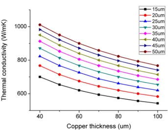
Dimensions of structure for simulation are 50 mm and 20 mm for length and width, respectively. Thicknesses of each layers are variable to find out effect of thickness to effective thermal conductivity. Simulation was conducted to find out thermal conductivity for various thickness of copper and graphene Fig. 2 shows thermal conductivity of the thick graphene embedded metal heat spreader for thickness of each layers. The thermal conductivity is in inverse proportion to thickness of metals. The reason is that effective thermal conductivity can be expressed as
(3)
from Eq. (2), in which x is the copper thickness and t
gis the graphene thickness.
2.2.2 Simulation for variable thickness ratio
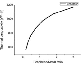
Fig. 3 shows the effective thermal conductivity for thickness ratio of graphene and metals when total thickness is fixed.
Effective thermal conductivity is increased rapidly when ratio is under 1, but after 1 increasing rate is getting slow down. The reason is that effective thermal conductivity can be expressed as K
effective2 K ⋅
cu⋅ t
cu+ K
g⋅ t
gt
total---
=
K
effK
cuK
g– K
cu( ) t ⋅
g2 x t ⋅ +
g--- +
= Fig. 1. Proposed graphene embedded metal heat spreader.
Table 2.1. Boundary conditions for simulations
Ambient temperature 25
oC
Gravity vector −9.8 m/s2
Meshes 0.8~1 M
Iterations 1000
Table 2.2. Material properties for simulation Material Density
(kg/m
3)
Specific heat (J/Kg · K)
Thermal conductivity
(W/m · K)
Copper 8933 385 401
Graphite 2100 720 1500/10
Fig. 2. Thermal conductivity for different thickness.
I 19 I
Thick Graphene Embedded Metal Heat Spreader with Enhanced Thermal Conductivity
J. Sensor Sci. & Tech. Vol. 23, No. 4, 2014 236 (4)
in which x is the ratio of graphene/metal. The reason of getting slow down of increasing rate when ratio is over 1, effect of graphene thermal conductivity is major portion.
3. FABRICATION
3.1 Fabrication Process
Since copper is nonreactive with carbon materials and the interfacial bonding is weak, resulting in high interfacial resistance and low thermal conductivity of metal structure [4]. Chromium is good adhesion layer not only for decreasing the thermal interfacial resistance between copper and graphene, but decreasing wetting angle for bonding between copper and graphene by. For this reason, chromium is picked for an adhesion layer and coated on both side of graphene by sputter.
To reduce the defect which come from the difference of coefficient of thermal expansion (CTE), bonding should be progressed in low temperature. Copper-copper direct bonding is adopted for low temperature bonding, and 1 um of copper was sputtered on both side of graphene right after 50 nm of chromium was sputtered. After that copper foil is bonded to graphene which was sputtered by chromium and copper at 25 kN and 250
oC for 1 hour [5]. At first, 25 kN pressure was applied on the sample and then temperature was increased to 250
oC for 30 minutes. After 1 hour bonding process, heater was turned off for cooling, this process takes 3 hour to approach the ambient temperature.
3.2 Fabrication Result
From the Eq. (3), effective thermal conductivity is higher when thermal conductivity of metal is higher. So bonding process was conducted for copper.
Fabrications were conducted for various dimension to find out effect of sample dimension. All samples are bonded.
Table 3.1 shows dimension of samples for fabrication.
Thickness of graphite and copper is measured by α-step and wafer thickness measurement device. Fig. 4 show front side after bonding process. At the edge which is not aligned, color of surface is changed.
4. MEASUREMENT
4.1 Angstrom's Method
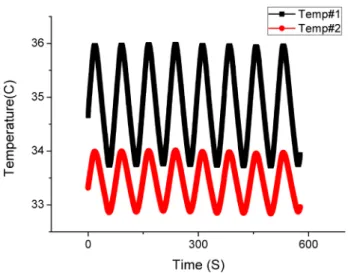
Measurement of the thermal conductivity is conducted by Angstrom's method [6]. Square wave is applied as input and sinusoidal temperature fluctuations from 2 thermocouples are output. Amplitude, frequency and phase difference could be obtained from the sinusoidal output. Using these data, effective thermal conductivity could be obtained with density and specific heat of structure.
Heat diffusion equation is K
effK
gr⋅ x 2 K + ⋅
cux 2 + ---
=
Fig. 3. Simulated thermal conductivity for ratio of thickness.
Table 3.1. Fabrication condition Sample Dimension
(cm)
Graphite thickness (um)
Copper Thickness (um)
#1 1 × 2 25 35
#2 1.5 × 3 25 35
#3 2 × 5 25 35
#4 5 × 8 25 35
Fig. 4. Front side of samples after fabrication.
I 20 I
Minsoo Park and Kukjin Chun
237 J. Sensor Sci. & Tech. Vol. 23, No. 4, 2014 (5)
in which K is the thermal conductivity, c is the specific heat and p is the density by Fourier's law. From Eq. (5) thermal conductivity can be obtained as.
(6)
4.2 Measurement of Thermal Conductivity
Dimension of samples for measurement is 2 cm and 5 cm for width and length, respectively. Angstrom's method was used to measure the effective conductivity of fabricated multilayered heat spreader. Fig. 5 shows temperature fluctuations at 2 thermistors which are separated by 10 mm.
Table 4.1 shows measurement of effective thermal conductivity from Angstrom's method. 685 W/m·K is obtained from simulation. 681, 694, and 684 W/m·K are obtained from measurement. The results show 0.6, 1.3, and 0.14% of errors.
5. CONCLUSIONS
This paper discussed about simulation, fabrication and measurement of thermal conductivity for thick graphene embedded metal heat spreader which has higher thermal conductivity than pure copper. Simulations were conducted for thickness of each layers and ration of thickness. Graphene is placed in between copper foils to overcome the disadvantage which is flaked off. Chromium layer is used as adhesion layer because copper is nonreactive with graphene. Chromium was sputtered on both side of graphene followed by copper for copper-copper bonding. Fabrication was conducted by hot pressing method at 25 kN, 250
oC for 1 hour. Thermal conductivity was measured by Angstrom's method. Measured thermal conductivity is 686 W/m·K and this result is 1.6 times higher than pure copper.
ACKNOWLEDGMENT
This work was supported by Inter-university Semiconductor Research Center.
REFERENCES
[1] W. Guy and W. Maltz, “Thermal management challenges in the passive cooling of handheld devices”, Thermal Investigations of ICs and Systems (THERMINIC), 2013 19th International Workshop on, pp. 344-347, IEEE, 2013.
[2] S. Krishna. “Power and thermal challenges in mobile devices”, Proceedings of the 19th Annual International Conference on Mobile Computing & Networking, pp. 363- 368, ACM, 2013.
[3] X. Qu, L. Zhang, M. Wu, and S. Ren, “Review of metal matrix composites with high thermal conductivity for ther- mal management applications”, Progress in Natural Sci- ence: Materials International, Vol. 21, Issue. 3, pp. 189- 197, 2011.
[4] P. B. Abel, A. L. Korenyi-Both, F. S. Honecy, and S. V.
Pepper, “Study of copper on graphite with titanium or chro- mium bond layer”, J. Mater. Res., Vol. 9, Issue. 3, pp. 617- 624, 1994.
[5] D. F. Lim, J. Fan, L. Peng, K. C. Leong, and C. S. Tan,
“Cu–Cu hermetic seal enhancement using self-assembled monolayer passivation”, J. Electron. Mater., Vol. 42, No. 3, pp. 502-506, 2013.
[6] A. L. Lytle, Angstrom's Method of Measuring Thermal Conductivity, Physics Department, The college of Wooster, Wooster, Ohio, 2000.
K∂
2