한 국 방 재 학 회 논 문 집 제10권 2호 2010년 4월
pp. 7 ~ 13
구조물방재
Moment Gradient Factor for Lateral Torsional Buckling Strength of Monosymmetric Stepped I-beam Subjected to Uniform Moment
Gelera, Kathleen Mae*·Park, Jong Sup**
···
Abstract
Stepped I-beams having increased moment of inertia at one end (singly stepped beam) or both ends (doubly stepped beams) can often be seen in construction of bridges due to material economy and easy fabrication of the section.This paper presents the results of the parametric study of lateral torsional buckling of monosymmetric stepped I-beams with constant depth subjected to uniform moment. Design recommendations were made based on the finite element results of the models having different com- binations of monosymmetric ratio, stepped length ratio, flange thickness ratio and flange width ratio. The proposed approximation is acceptable based on the parameters given having mostly conservative results. The proposed equation can be further used to extend the study to different loading conditions.
Key words :monosymmetric beam, stepped beam, lateral torsional buckling, moment gradient factor 요 지
단순보 끝단의 단면을 증가시키는 일단과 양단 계단식 단면 변화 I형보는 경제적인 단면활용과 제작의 편의성으로 인하여 교 량제작에 널리 사용되고 있다. 본 연구는 균일 모멘트를 받는 일축대칭 I형 스텝보의 횡-비틀림 좌굴 강도에 관한 연구이다.
유한요소해석이 본 연구에 활용되었으며, 해석매개변수로는 단면변화 길이 비율, 플랜지두께 변화 비율과 플랜지폭 변화 비율 및 다양한 일축대칭비율이 고려되었다. 해석결과를 토대로 제안된 설계강도식은 대부분의 경우에 안전측의 값을 나타내고 있으 며, 향후 다양한 하중조건을 고려한 설계식 개발에 활용될 수 있을 것이다.
핵심용어 : 일축대칭보, 스텝보, 횡-비틀림좌굴, 모멘트구배계수
···
1. Introduction
The use of stepped I-beams in construction is gaining popularity specifically in steel bridges and buildings. The reason is that in beams, the maximum moment is often reached locally and the moment at the rest of the beam is significantly reduced. Therefore, material economy can be achieved by reducing the member section in the low moment area. Steps in beams are achieved by either adding cover plates to beam flanges, changing the size of the cross section for hot rolled beams or by changing the flange dimension for built up sections. Stepped beams are most efficient when laterally supported because the strength of the material is used to its full extent. When adequate lateral support is not provided, its failure is often caused by lateral torsional buckling. But the use of stepped beams can still be economical as long as the flange material is distributed to improve its resistance.
Even though the use of stepped beam is gaining popular- ity, only few researches have been published. Before, it was a common practice of designers to calculate the lateral tor- sional buckling (LTB) of stepped beams either by assuming that it is prismatic using the properties of the smaller cross section or by using a weighted average approach. The first method provides a very conservative solution while the sec- ond one provides an unconservative estimate. Trahair and Kitipornchai (1971) investigated the effect of LTB on sim- ply supported beam stepped at midspan. Recently, Park (2004) wrote a research regarding LTB of beams which has abruptly increased sections at ends of beams. All these researches on stepped beams have been mostly limited to doubly symmetric I-beams. Some of the equations devel- oped were for general loading conditions of simply sup- ported beams and continuous beams with top flange bracing.
The effect of span-to-height ratio (Lb/h) on lateral torsional buckling has also been studied.
**Sangmyung University, Dept. of Civil Engineering, Master Student of Engineering (E-mail: [email protected])
**Sangmyung University, Dept. of Civil Engineering, Assistant Professor (Corresponding Author)
This paper extends the previous study on lateral torsional buckling of doubly symmetric stepped beams subjected to uniform moment written by Park and Kang (2004) to vary- ing monosymmetric ratios. The results of the parametric analysis of lateral torsional buckling of monosymmetric stepped I-beams with constant depth subjected to uniform moment are presented here. This study is only limited to I- beams with degree of monosymmetry, ρ, between 0.1 and 0.9. The degree of monosymmetry, ρ, is defined as the ratio of the second moment of area of the top flange about the y- axis (IyT) to the second moment of area of the whole beam (Iy). Sections with values of ρ that were not included, which are basically tee sections, have lateral torsional buckling strength which are very hard to predict due to local buckling and web distortion. The parameters used for stepped beams are taken from the geometry of real bridges as reported by Park and Stallings (2003). This paper presented a solution that is similar to current lateral torsional buckling solution which uses a modifier, Cst, to consider the effect of the change in cross section.
2. Background and Previous Studies
Lateral Torsional Buckling behaviour of beams has been widely studied by researchers for years. Researches were published for different steel beam sections, loading condi- tions, boundary conditions and methods for producing a new equation. One of the most important researches on the monosymmetric beams came from Kitipornchai and Trahair (1980) who discussed the important properties of these sec- tions and its effects on its lateral torsional buckling. Some of these properties are degree of monosymmetry (ρ), mono- symmetry parameter (βx), and beam parameter (K). The most important factor that differentiates doubly symmetric beams from monosymmetric beams is the monosymmetry parameter βx also known as the Wagner Effect. This arises from the bending compressive and tensile stresses that form a resultant torque when the beam twists during buckling.
For doubly symmetric I-beams, the compressive stresses are balanced by the tensile stresses so βx is zero. However, for monosymmetric I-beams, there is an imbalance and the resultant torque causes a change in the effective torsional stiffness. When the smaller flange is in compression, there is a reduction in the effective torsional stiffness while the reverse is true when the smaller flange is in tension. Trahair (1993) presented graphical solutions for simply supported monosymmetric I-beams with concentrated load, uniform load and varying end moments. Helwig et al (1997) sug- gested a simplified equation for monosymmetric I-beams subjected to general loading conditions applied at different load heights.
SSRC Guide (1998) presented a solution for lateral tor-
sional buckling of monosymmetric I-beams subjected to uniform moment along the unbraced length.
(1a) with (1b)
with (1c)
with (1d)
where L = unbraced length; E = modulus of elasticity; Iy = second moment of area of section about y-axis; G = shear modulus; J = St. Venant torsional constant; K = boundary coefficient; h = distance between the centroid of the top and bottom flanges; and Cw = warping constant.
Most design equations for stepped beams present a buck- ling solution for prismatic beams and then apply a factor to account for the effect of abrupt increase in moment of iner- tia along the unbraced length. Trahair and Kitipornchai (1971) studied the effects of step locations in the minor axis flexural rigidity, torsional rigidity and warping rigidity of beams. It was found that steps located on the flange width and flange thickness have the greatest effect on the lateral torsional buckling resistance of step beams. The following approximate solution for the elastic LTB resistance moment (Mst) of stepped beam of constant depth was presented
Mst=αstMyz= [1−2.4α(1− βγ)]Myz (1) where Myz=LTB moment resistance of an equal length pris- matic beam having the larger cross section along the entire span; and α, β and γ = ratios defining the relative length, width and thickness of large and small cross sections respec- tively. An experimental study confirms the presented approximation.
In 2002, Park started a series of researches on the effect of LTB on stepped beams considering two general types which are doubly stepped beams and singly stepped beams.
Doubly stepped beams are beams with increased moment of inertia at both ends while singly stepped beams are beams having increased moment of inertia at one end. Park and Kang (2004) suggested the following equation for the lateral torsional buckling of doubly stepped and singly stepped beams subjected to pure bending
Most = CstMocr (2a)
Cst = 1 + 3.6α2(βγ1.3-1) Doubly Stepped Beam (2b) Cst = 1 + 1.5α1.6(βγ1.2-1) Singly Stepped Beam (2b) in which Mocr=LTB strength of prismatic beam with smaller cross section; α, β and γ = ratios of stepped lengths, flange widths and flange thicknesses respectively. Park
Mocr π
KL--- EIyGJ B⎝⎛ 1+ 1+ +B2 B12⎠⎞
=
B1 πβx
2(KLb)
--- EI---GJy
=
B2 π2ECw KL ( )2GJ
---
=
Bx 0.9h 2Iyc Iy
--- 1–
⎝ ⎠
⎛ ⎞ 1 IIy ----x
⎝ ⎠⎛ ⎞2
–
=
(2002) developed equations for LTB of stepped beams with continuous top flange bracing while Park and Stallings (2003) proposed an equation applicable to various loading and boundary conditions.
3. Finite Element Modeling
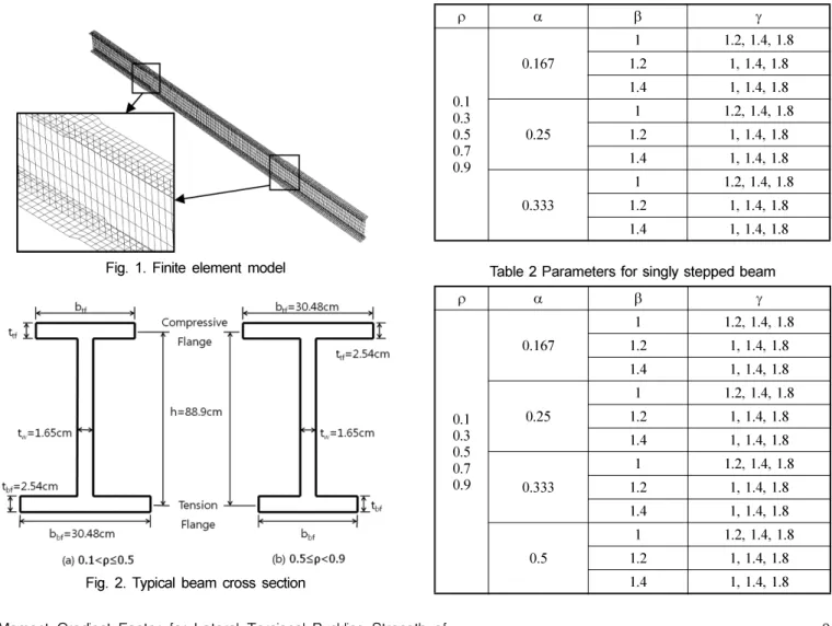
Elastic finite element models of monosymmetric stepped beams described below were developed using ABAQUS (2007). The cross section of the beams were built up using S4R shell elements which was chosen because of its capa- bility to provide enough degrees of freedom to clearly model buckling deformations of the beam. S4R is a three dimensional, doubly curved, 4-noded shell element. A con- vergence test was performed to check the optimum mesh that will provide accurate results without consuming too much space and time in the process. Based on the results of the test, the top and bottom flange has 4 to 8 elements and the web has 6 elements. The typical finite element model and a blow up of the abruptly increased section are shown in Fig 1.
The typical I-beam cross section profiles are shown in Fig 2. One of the parameters examined here is the monosym- metric ratio. Monosymmetric ratio (ρ=Iyc/Iy) is defined as the ratio of the moment of inertia of the compression flange and the weak-axis moment of inertia of the whole beam.
The ratios included in the study are between 0.1 and 0.9 at 0.2 intervals. For beams having a monosymmetric ratio 0.1<
ρ≤0.5, the bottom flange is fixed at 30.48×2.54 cm and the top flange is changed to generate the required ρ. For beams having a monosymmetric ratio 0.5≤ρ<0.9, the top flange is fixed at 30.48×2.54 cm and the bottom flange is varied to achieve the required ρ. Beams with ratio of ρ is just an inverse of beams with ratio of 1-ρ. And a beam having a ratio of 0.5 is a doubly symmetric beam. In terms of prac- ticality, it was published in some journals that beams having
ρ=0.9 have higher LTB resistance as compared with beams having ρ=0.1. The beam height and web thickness is fixed at 88.9×1.65 cm. Other monosymmetric beams such as tee beams and inversed tee beams were not included because their buckling behavior is very difficult to predict due to sig- nificant web distortion and local buckling.
Stepped beams are nonprismatic beams which has an abrupt change in cross section. Two types of stepped beams were considered in the investigation: doubly stepped beam, which has increased section at both ends and singly stepped beam, which has increased section at one end. The parame- ters for doubly and singly stepped beams were shown in Tables 1 and 2. These ratios were taken from Park (2004) which was based from the geometry of actual bridges. The
Fig. 1. Finite element model
Fig. 2. Typical beam cross section
Table 1 Parameters for doubly stepped beam
ρ α β γ
0.10.3 0.50.7 0.9
0.167 1 1.2, 1.4, 1.8
1.2 1, 1.4, 1.8
1.4 1, 1.4, 1.8
0.25 1 1.2, 1.4, 1.8
1.2 1, 1.4, 1.8
1.4 1, 1.4, 1.8
0.333 1 1.2, 1.4, 1.8
1.2 1, 1.4, 1.8
1.4 1, 1.4, 1.8
Table 2 Parameters for singly stepped beam
ρ α β γ
0.10.3 0.50.7 0.9
0.167 1 1.2, 1.4, 1.8
1.2 1, 1.4, 1.8
1.4 1, 1.4, 1.8
0.25 1 1.2, 1.4, 1.8
1.2 1, 1.4, 1.8
1.4 1, 1.4, 1.8
0.333 1 1.2, 1.4, 1.8
1.2 1, 1.4, 1.8
1.4 1, 1.4, 1.8
0.5 1 1.2, 1.4, 1.8
1.2 1, 1.4, 1.8
1.4 1, 1.4, 1.8
definition of α, β and γ can be found on Fig. 3a for doubly stepped beams and Fig. 3b for singly stepped beams. A beam with β=1 and γ=1 is a prismatic beam. Beams lengths of 13.2m (Lb/h=15), 17.7m (Lb/h=20) and 22.2m (Lb/h=25) were investigated to consider the effect of span-to-height ratios.
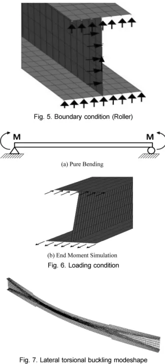
Figs 5 and 6 show the boundary and loading conditions used to simulate the required simply supported condition and end moment. An ideal simply supported condition was used here. It means that both ends are restricted against ver- tical deflection, out-of-plane deflection and twist rotation but free against in-plane rotation, minor axis rotation and warping displacement while only one end is fixed against longitudinal horizontal displacement. End moments were simulated by applying concentrated horizontal loads at the beam end nodes of the flanges. The top flange was sub- jected to compressive force while the bottom flange was subjected to tensile force. The uniform moment was achieved by having equal values of end moments but with opposite directions.
When subjected to uniform moment, monosymmetric stepped I-beams leads to a buckling mode which is charac- terized by lateral deflection and twist, as shown in Fig. 7.
Local buckling such as web distortion was not considered.
4. Finite Element Results
Elastic eigenvalue analyses were conducted to determine bifurcation loads for all the parameters considered and dis- cussed in the preceding section which has 27 models for doubly stepped beams and 36 models for singly stepped beams for every monosymmetric ratio investigated. The elastic buckling moment results were used to calculate the stepped beam correction factor, Cst, which is defined as the ratio between the maximum eigenvalue of the stepped beam and the buckling capacity of the prismatic beam having the smaller section (Most/Mocr). The results from the finite ele- ment analyses were tabulated and a design equation was for- mulated using a statistical regression program, Minitab 14 (2007). The lateral torsional buckling capacity of monosym- Fig. 3. Definition of α, β and a for doubly stepped beam
Fig. 4. Definition of α, β and a for singly stepped beam
Fig. 5. Boundary condition (Roller)
Fig. 6. Loading condition
Fig. 7. Lateral torsional buckling modeshape
Fig. 8. Results for doubly stepped beam
Fig. 9. Results for singly stepped beam
metric stepped I-beams subjected to pure bending is given as
Most = CstMocr (3a)
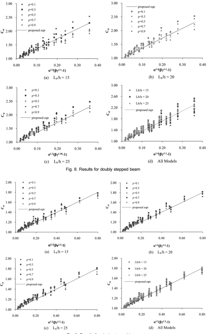
Cst = 1 + 3.6α1.4(βγ1.1-1) Doubly Stepped Beam (3b) Cst = 1 + α1.2(βγ1.2-1) Singly Stepped Beam (3c) where α, β and γ = stepped length ratio, flange width ratio and flange thickness ratio is as defined in Figs 3 and 4.
Figs. 8a, 8b and 8c shows that Cst varies linearly with
α1.4(βγ1.1-1) for doubly stepped beams having Lb/h of 15, 20 and 25, respectively. The results from finite element analy- ses (FEA) were plotted along with the results from the pro- posed equation. The dots represent the finite element results and the solid line represents the proposed equation. Except for a few isolated cases, the proposed equation gives con- servative results and is concurrent with the finite element results. The maximum difference of the conservative esti- mate is 19% with ρ=0.1, α=0.333, β=1 and γ=1.8. The max- imum difference of the unconservative estimate is 20% with
ρ=0.9, α=0.333, β=1.4, and γ=1.8.
Figs. 9a, 9b and 9c present the results of the finite element analyses and the proposed equation of singly stepped beams having Lb/h of 15, 20 and 25. This graph shows that Cst var- ies linearly with α1.2(βγ1.2-1). The dots and solid lines are results based on the finite element analyses and the pro- posed equation, respectively. The proposed equation pro- duces an approximation that is acceptable within the given parameters having a difference of -6% to 11%. The solution is the most conservative with ρ=0.7, Lb/h=20, α=0.5, β=1.2, and γ=1 and the most unconservative with ρ=0.9, Lb/h=15,
α=0.333, β=1.4, and γ=1.8.
In Figs. 8d and 9d, graphs comparing the results of all the models (Lb/h = 15, 20 and 25) for doubly and singly stepped beams, respectively, are presented. As the Lb/h ratio increases, Cst also increases. The new equations presented have results that are either conservative or unconservative for different cases. However it is a simple equation that pro- duces reasonable estimates. Also, the proposed equation can be further used to extend the study and propose equations applicable to general loading condition.
5. Conclusion
The results from the numerical studies using finite ele- ment analyses have been presented for doubly stepped beams with varying degree of monosymmetry (0.1≤ρ≤0.9). A uniform moment was applied along the length of the beam.
Using the FEA results, a design recommendation for the lat- eral torsional buckling of monosymmetric doubly and singly stepped beams were developed. It was observed that the change in flange thickness is more significant than the change in flange width and the lateral torsional buckling increases as
the span-to-height ratio increases. With the exemption of few isolated cases, the suggested equations generally pro- duce conservative results and were in agreement with the FEA results. The proposed equation can be further used to extend the study to different loading conditions.
Appendix: Example Problem
A simply supported beam with 15m long is subjected to pure bending. The beam sections and other properties are given below. Compute the lateral torsional buckling capacity of the beam.
α= 5/15 = 0.333, β= 38.1/30.48 = 1.25, γ= 3.05/2.54 = 1.2 Cst= 1 + 3.6α1.4(βγ1.1-1) = 1.136
Most = CstMocr = (748) (1.136)= 850 kN-m
Proposed Equation FEM (Abaqus) Difference
850 kN-m 862 kN-m 1.38%
Mocr π
KL--- EIyGJ B⎝⎛ 1+ 1+ +B2 B12⎠⎞ 748kN m–
= =
B1 πβx
2(KL)
--- EI--- 0.39455GJy
= =
B2 π2ECw KL ( )2GJ
--- 0.46499
= =
βx 0.9h2lyc Iy
--- 1–
⎝ ⎠
⎛ ⎞ 1 IIy ----x
⎝ ⎠⎛ ⎞2
– 0.49316
= =
Notation
Acknowledgments
This work was supported by the National Research Foun- dation (NRF) grant funded by the Korean government (Min- istry of Education of Science and Technology, MEST) (2009-0077931) and was also supported by the 2009 research grant funded by the Engineering Research Center in Sangmyung University.
References
ABAQUS (2007) Standard User’s Manual, Hibbit, Karlsson and Sorensen, Inc., Version 6.7.
American Institute of Steel Construction (2005) AISC LRFD Speci- fication, 4thEdition, Chicago, Illinois.
Galambos, T.V, (1998) Guide to Stability Design Criteria for Metal Structures, Wiley, New York, NY.
Helwig, T.A., Frank, K.H. and Yura, J.A. (1997) “Lateral-Torsional Buckling of Singly Symmetric I-beams.” Journal of Structural Engineering, ASCE, Vol. 123, No. 9, pp.1172-1179.
Kitipornchai, S. and Trahair, N.S. (1980) “Buckling Properties of Monosymmetric I-beams.” Journal of Structural Engineering, ASCE, Vol. 106, No. 5, pp.941-957.
MINITAB 14 (2007) Statistic, Minitap Inc.
Park, J.S. (2002) “Lateral Torsional Buckling of Prismatic Beams with Continuous Top Flange Bracing.” Journal of Construc- tional Steel Research, Vol. 60, Issue 2, pp.147-160.
Park, J.S. and Stallings, J.M. (2003) “Lateral-Torsional Buckling of Stepped Beams.” Journal of Structural Engineering, ASCE, Vol.
60, Issue 2, pp. 147-160.
Park, J.S. and Kang, Y.J. (2004) “Flexural-Torsional Buckling of Stepped Beams Subjected to Pure Bending.” Journal of Civil Engineering, KSCE, Vol. 8, No. 1, pp.75-82.
Trahair, N.S. (1993) Flexural Torsional Buckling of Structures, CRC Press, Boca Raton, Fla.
Trahair, N.S. and Kitipornchai, S. (1971) “Elastic Lateral Buckling of Stepped I-Beams.” Journal of Structural Engineering, ASCE, Vol. 97, No. 10, pp. 2535-2548
◎논문접수일 : 10년 01월 28일
◎심사의뢰일 : 10년 02월 04일
◎심사완료일 : 10년 03월 09일
Cbst = moment gradient factor
Cbst = moment gradient modifier for stepped beam CW = warping constant
E = modulus of elasticity of steel G = shear modulus of elasticity of steel Iy = moment of inertia about Y-axis
Iyc = moment of inertia of top flange about Y-axis J = torsional constant
K = boundary coefficient L = laterally unbraced length
MA = absolute value of moment at quarter point of the unbraced length
MB = absolute value of moment at midpoint of the unbraced length
MC = absolute value of moment at three-quarter point of the unbraced length
Mcr = lateral torsional buckling of prismatic beam subjected to general loading conditions
Mmax = absolute value of maximum moment along the unbraced length
Mocrr = lateral torsional buckling of prismatic beam subjected to constant moment
Most = lateral torsional buckling of stepped beam subjected to constant moment
Mst = lateral torsional buckling of stepped beam subjected to general loading conditions
α = ratio of stepped length to the unbraced length
β = ratio of the smaller to larger flange widtth
γ = ratio of the smaller to larger flange thickness
ρ = monosymmetric ratio