Superconductivity and Cryogenics Vol.13, No.4, (2011), pp.18~21
```
Abstract-- In this work, the yttrium oxide(Y2O3) thin films as the buffer layer were prepared by the simple solution coating and reel-to-reel process on an unpolished metal tape substrate. The Y2O3 thin films were successfully synthesized by the hydrolysis of yttrium acetate. We have studied the improvement of surface roughness with the concentration of solution(0.1 M, 0.4 M, M) and the number of coatings. The planarization by solution coating process is simple in comparison with the existing polishing process, and it is eco-friendly, and has the benefits of low cost process. The thickness of Y2O3 films was increased with the Y2O3
concentration in the solution, and the surface became smoother with the number of coating cycles. Using this process, we have achieved 1.2 nm RMS roughness from a starting roughness of over 31 nm on 25 μm2 area.
1. INTRODUCTION
The application of flexible substrate for the thin film deposition is various such as the displays of electronic application devices, printed circuit boards, the solar cells &
batteries using advanced energy materials and high temperature superconductor coated conductors [1]. In case of flexible substrate, it has the benefits of low-cost manufacturing, small volumes and light weight. However, the flexible substrate cannot often be provided in various fields in spite of low-cost manufacturing because it does not meet the surface roughness required for the deposition of thin films. The planarization process has the things like mechanical and electro-chemical polishing. This process makes the deposition of thin films easy by decreasing the roughness of surface. In this study, we performed the planarization for metal tape substrate of rough surface by multi-coating with Y2O3 solution through solution dip coating process and conversion heat treatment.
The solution coating process is eco-friendly, simple, and cost-effective for various alloy substrates. The amorphous Y2O3 thin film formed by repeated coating decreases the roughness of substrate surface, and it performs the role of diffusion barrier preventing the diffusion of harmful element out of metal substrate. In case of manufacturing process of IBAD-MgO coated conductor template, the ______________________________________________
*Corresponding author: [email protected]
Y2O3 and Al2O3 is deposited by the evaporation in order to provide diffusion barrier layer after the process of electro polishing for the planarization of metal substrate [2-5].
However, we are going to make the substrate available for IBAD_MgO process in order to make the process simple and the manufacturing cost low. In this study, the Y2O3 thin film, which is to have been planarized and performs the role of diffusion barrier on the unpolished metal tape substrate through the solution coating process, is fabricated continuously using a reel-to-reel system.
2. EXPERIMENTS 2.1. Reagents and measurements
In this experiment, we used the yttrium acetate tetrahydrate(Alfa Aesar Chemical Co., 99.9%) as a starting precursor. The methyl alcohol(Aldrich Chemical Co., 99+%) and the diethanoltriamine(Samchun Chemical Co., 99%) were used as solvents, and the 2-propanol(Samchun Chemical Co., 99.5%) was used as received without further refining.
The surface morphology analysis was performed by using a scanning electron microscope(S4800, HITACHI, Japan), and the analysis of surface composition was performed by using an energy dispersive spectroscope(JSM-6330F). The coating thickness and quality of interface were confirmed using the HR-TEM cross sectional micrograph. The surface roughness was measured by using an atomic force microscope(XE-100, Park system, Korea), and the crystallographic characteristics of samples was analyzed by using the X-ray diffraction (X-pert PRO MPD, Philips, Netherlands).
2.2. Synthesis
The sol synthesis of coating solutions with various molarities of 0.1 M, 0.4 M, 0.6 M were performed by using a three way round bottom flask of on a heating mantle equipped the PID controller. We stirred the loaded mixture of yttrium acetate tetrahydrate and methanol for 1 hour at about 55 °C. After adding the diethanoltriamine by using the syringe, we stirred it for 2 hours at room temperature.
Prepared solution was filtered through the 0.22 μm PTFE syringe filter before coating [6].
Planarization of flexible tape substrate by solution coating process
Boo Min Kang1,2, Rock Kil Ko1,3, Dong Hyuk Kim1,4, Dong Woo Ha1, Seong Soo Park2*
1Korea Electrotechnology Research Institute, Changwon, Korea
2Applied Chemical Engineering, Pukyong National University, Busan, Korea
3Physics, Pusan National University, Busan, Korea
4Biomedical Sciences & Engineering, Inje University, Kimhae, Korea Received 31 October 2011; accepted 21 November 2011
Boo Min Kang, Rock Kil Ko, Dong Hyuk Kim, Dong Woo Ha, and Seong Soo Park
2.3. Tape Substrate Coating
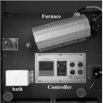
In this experiment, amorphous-Y2O3(a-Y2O3) thin films were coated on a metal tape using continuous reel-to-reel tape loop coater by a dip coating method. Reel-to-reel tape loop coater is operated by performing a dipping of a metal tape substrate into the bath and a conversion heat treatment repeatedly. The basic equipments are composed of a solution bath, a tube furnace to heat the metal substrate up to a conversion temperature, a tension meter to control the tension of metal tape substrate and a motor for continuous movement of metal tape substrate. The Fig. 1 shows a reel-to-reel tape loop coater system used in this experiment.
The Hastelloy C-276 metal tape of 0.05 mm thickness was used as a substrate. The metal substrate had a RMS roughness of 67 nm at the scale of 20 μm × 20 μm and had the roughness of 31.8 nm RMS at the scale of 5 μm × 5 μm, respectively. The substrate moving speed was 100 mm/min.
The dip coating bath consists of the pulley to rotate freely in order that the metal substrate is dipped into the solution with moving, the teflon bath to contain the liquid and the doorway to put in the liquid or to move the metal substrate.
The conversion to Y2O3 thin films was taken place to the in the temperature range of 500 ± 10 °C when a coated substrate was passing through a quartz tube of 30 mm diameter and 300 mm length inside the furnace. The dry air was flowed with a flow rate of 63 sccm removes the moisture and by-product inside a quartz tube generated during conversion heat treatment. The multiple coating and conversion heat treatment was performed by using the the continuous reel-to-reel coating and heat treatment system.
We prepared the Y2O3 solution with different molarities(0.1 M, 0.4 M, 0.6 M) in order to coat the Y2O3
thin film as a buffer layer on the unpolished Hastelloy metal tape substrate. Using these solutions, we evaluated the planarization of substrate depending on the molarity of coating solution and the number of coatings(1~30 times).
Controller bath
Furnace
Fig. 1.Reel-to-reel tape loop coater.
Fig. 2. EDS of the Y2O3 films prepared using the coating solutions with various molaries of 0.1 M, 0.4 M and 0.6 M.
Fig. 3. XRD patterns of Y2O3 films and bare substrate (A) before heat treatment (B) after heat treatment at 900 °C . Molarities of coating solution were 0.1 M(a), 0.4 M(b), 0.6 M(c) and Hastelloy(d).
We presented an average value of the surface roughness by measuring 5 times at five different positions in the area of 5 μm x 5 μm using AFM.
3. RESULTS AND DISCUSSION
The surface compositions of Y2O3 thin film prepared using the solution coating with various molarities were analyzed qualitatively by EDS and are shown in Fig. 2.
Since only yttrium and oxygen elements were detected, it can be thought that the Y2O3 was synthesized on a metal substrate.
XRD patterns of coated films were obtained in order to characterize the crystallographic structure of coated films after a heat treatment for 1 hour at 900 °C whether formed Y2O3 thin film is amorphous state or not [3, 7]. From Fig. 3, it can be observed that the XRD peaks from crystalline Y2O3 are appeared after the heat treatment while no clear XRD peaks are detected for the Y2O3 thin film before the heat treatment. It is also seen that XRD peaks becomes stronger with the molarity of coating solution.
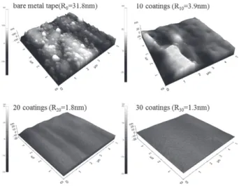
Figure 4 shows the AFM images that show the roughness change of substrate surface depending on the number of coatings of the Y2O3 thin film prepared using 0.4 M solution. The surface roughness(Rrms) of starting unpolished Hastelloy substrate was 31.8 nm at the scale of 5 μm × 5 μm. It can be seen that the surface roughness was dramatically improved to 1.3 nm at the scale of 5 μm × 5 μm after coating 30 times by the solution coating process.
19
Planarization of flexible tape substrate by solution coating process
G
Fig. 4. AFM images as a function of the number of coatings for 0.4 M solution.G
0 5 10 15 20 25 30
1 10
Roughness (nm)
Number of solution coating
0.1M 0.4M 0.6M R0= 31.8 nm
G
Fig. 5. RMS roughness as a function of the number of solution coating.
The planarization of the surface roughness of 1.3 nm and 1.2 nm, respectively, was achieved at the scale of 5 ȝm
× 5 ȝm when coating 30 times for the solution molarity of 0.1 M and 0.6 M. We observed that the reduction of roughness occurred through the decline of bumpy areas on surface after evaporation of solvent. After shrinking into solid state by evaporation of solvent, some areas of substrate showed similar surface roughness after conversion heat treatment. However, the degree of roughness is reduced compared to that of starting substrate.
The Fig. 5 shows the roughness change of Y2O3 thin film depending on the number of coatings by using the solution of different molarities. It can be seen that the shrinkage of thin film decreases with the molarity of coating solution.
It is also revealed that the degree of the improvement of surface roughness is decreased as the number of coating is increased. The reduction The reduction of roughness occurs rapidly in the early time in case of high molarity solution while the ratio of roughness reduction uniformly declines in case of low molarity solution.
Fig. 6.GSEM images of the Y2O3Gfilms for 0.1 M, 0.4 MGand 0.6 M.
G
The changes of surface morphology pursuant to the molarity of solution were represented in Fig. 6. Figure 6 (a) shows the surface of unpolished Hastelloy substrate which has lots of defects such as the pits, particles and scratch formed during manufacturing process. However, the surface became clean by the repeated solution coating process(Fig. 6 (b), (c)). Use of the coating solution with higher molarity of 0.4 M resulted in cleaner surface compared with that of low molarity solution. It was also observed that cracks and micropores in some area were formed in case of 0.6 M solution(Fig. 6 (d)).
Figure 7 shows the HR-TEM cross sectional micrograph for the Y2O3 samples prepared by using a focused ion beam(FIB). We could observe the interface boundaries between each Y2O3 layers formed by repeated coatings from the TEM images. The thickness of total Y2O3 coating layers was 0.5 ȝm, 0. ȝm and 1.2 ȝm for 0.1 M, 0.4 M and 0.6 M solution, respectively. The interface boundaries between coating layers is not clear in case of low number of coatings. It is considered that it becomes clear according to the improvement of surface roughness by increasing the number of coatings. It was observed that the thickness of the coated Y2O3 thin film was increased with the molarity of Y2O3 solution increasing.
G Fig. 7.GFIB-TEM image of Y2O3Gfilm for 0.4 MGsolution-30 coatings. G
20
Boo Min Kang, Rock Kil Ko, Dong Hyuk Kim, Dong Woo Ha, and Seong Soo Park
4. CONCLUSION
We manufactured successfully the Y2O3 thin film as buffer layer which performs the function of diffusion barrier and makes the surface of substrate planarize at the same time through the solution coating process by coating.
The higher molarity of coating solution and thicker Y2O3
thin film planarized the substrate surface by decreasing the roughness of surface with the number of coatings. The roughness value of initial 31.8 nm surface was planarized as the roughness of surface close to 1nm by the solution coating process of 30 times.
REFERENCES
[1] H.L. Chen, J. Hou, I. McCulloch, G.B. Raupp, and V. Subramanian,
"Special issue on flexible electronics and displays," Journal of Display Technology, vol. 5, pp. 169-171, 2009.
REFERENCES
[2] H.L. Chen, J. Hou, I. McCulloch, G.B. Raupp, and V. Subramanian,
"Special issue on flexible electronics and displays," Journal of Display Technology, vol. 5, pp. 169-171, 2009.
[3] V. Selvamanickam, J. Dackow, and Y. Xie "Progress in superpower's 2G HTS wire development program," FY2009 Superconductivity for Electric Systems Peer Review, Alexandria, VA, Aug. 4-7, 2009.
[4] V. Matias, and P. Clem, "Sustaining innovation in coated conductors IBAD template and reactive co-evaporation,"
Superconductivity for Electric Power Systems Annual Review, Arlington, VA, Aug. 7-9, 2007.
[5] V. Selvamanickam, J. Dackow, and Y. Xie "Progress in superpower's 2G HTS wire development program," FY2009 Superconductivity for Electric Systems Peer Review, Alexandria, VA, Aug. 4-7, 2009.
[6] V. Matias, and R. H. Hammond "YBCO superconconductor wire based on IBAD-textured templates: Design, performance and cost possibilities," EUCAS ISEC ICMC 2011, Hague, Netherlands, Sep.
18-23, 2011
[7] L. Lou, W. Zhang, A. Brioude, C. Le Luyer, J. Mugnier,
"Preparation and characterization of sol-gel planar Y2O3
waveguides," Optical Materials, vol. 18, pp. 331-336, 2001.
21