논문 2014-51-6-10
질량-스프링 구조를 이용한 새로운 광세기 기반 광섬유 진동센서
( Novel Intensity-Based Fiber Optic Vibration Sensor Using Mass-Spring Structure )
호 일*, 김 현 호*, 최 상 진*, 반 재 경***
( Hao Yi, Hyeon-Ho Kim, Sang-Jin Choi, and Jae-Kyung Pan
ⓒ)
요 약
본 논문에서는 질량-스프링 구조를 이용한 새로운 광세기 기반 광섬유 진동센서를 제안하고 시뮬레이션과 부분 실험을 통 하여 그 실현 가능성을 제시한다. 제안한 광세기 기반 광섬유 진동센서는 네 개의 구불구불하게 휘어지는 스프링과 질량체 안 의 사각형 개구면(aperture)으로 구성된 질량-스프링 구조를 가진다. 광시준기(optical collimator)는 질량체 안의 사각형 개구면 의 변위에 의해서 변조되는 광을 넓히는 데 이용된다. 제안한 광섬유 진동센서를 광학적인 면과 기계적인 면에서 해석하고 설 계한다. 기계적인 부분의 설계는 이론적인 해석, 수학적인 모델링 및 3 차원 유한요소법 시뮬레이션을 이용한다. 기계적인 진 동이 가해질 때 개구면의 상대적인 변위관계를 3차원 유한요소법 시뮬레이션을 이용하여 구하고, 개구면의 상대적인 변위에 따른 출력값을 실험을 통하여 측정한다. 이를 이용하여 진동에 따른 출력 특성을 파악한 결과 센서 민감도 15.731 μW/G, 감지 영역 ±6.087 G를 얻었다. 그리고 입력광원의 파워가 10 dB까지 변하더라도 참조광을 이용하여 0.75%의 상대오차를 보이는 매 우 안정된 출력광 파워를 얻었다. 제안한 광섬유 진동센서는 간단한 구조, 저비용 및 다지점 측정 가능의 특징을 가지면서, MEMS (Micro-Electro-Mechanical System) 기술을 이용하여 소형으로 간편하게 제작할 수 있는 잠재력을 가진다.
Abstract
In this paper, a novel intensity-based fiber optic vibration sensor using a mass-spring structure, which consists of four serpentine flexure springs and a rectangular aperture within a proof mass, is proposed and its feasibility test is given by the simulation and experiment. An optical collimator is used to broaden the beam which is modulated by the displacement of the rectangular aperture within the proof mass. The proposed fiber optic vibration sensor has been analyzed and designed in terms of the optical and mechanical parts. A mechanical structure has been designed using theoretical analysis, mathematical modeling, and 3D FEM (Finite Element Method) simulation. The relative aperture displacement according to the base vibration is given using FEM simulation, while the output beam power according to the relative displacement is measured by experiment. The simulated sensor sensitivity of 15.731 μW/G and detection range of ±6.087 G are given. By using reference signal, the output signal with 0.75% relative error shows a good stability. The proposed vibration sensor structure has the advantages of a simple structure, low cost, and multi-point sensing characteristic. It also has the potential to be made by MEMS (Micro-Electro-Mechanical System) technology.
Keywords: vibration sensor, intensity-based, fiber optic sensor, mass-spring structure
* 학생회원, ** 평생회원, 전북대학교 전기공학과, 스마트그리드연구센터
(Department of Electrical Engineering, Smart Grid Research Center, Chonbuk National University)
ⓒ Corresponding Author(E-mail: [email protected])
※ 이 논문은 2013년도 정부(미래창조과학부)의 재원으로 한국연구재단의 지원을 받아 수행된 연구임.
(2010-0028509, 2011-0010473)
접수일자: 2014년03월10일, 수정일자: 2014년05월12일, 수정완료: 2014년05월28일
Ⅰ. Introduction
Vibration measurement plays a major role in studying the dynamic behaviour and monitoring the health condition of machines. To avoid unpredicted failure and losses, it is very important to improve the reliability and accuracy of the sensors used for vibration monitoring[1-2]. Traditional piezoelectric vibration sensors and magnetoelectric vibration sensors make a great contribution to scientific research and automate production process[3-4]. Compared to traditional piezoelectric vibration sensors and magnetoelectric vibration sensors, fiber optic sensors (FOSs) are suitable for long distance detection and have the advantages of small size, light weight, and good immunity to electromagnetic fields[5-6]. Three types of FOSs are mainly used in vibration detection: Fabry-Perot (FP) interferometers, fiber Bragg grating (FBG) sensors and intensity-based FOSs.
FP interferometers are passive optical structures that utilize multiple-beam interference in a cavity between two semi-reflective surfaces. They provide high precision and some techniques such as wavelength division. Transmitted and received optical signals can be used to obtain excellent relation with displacement strain and vibration measurement. But the imperfections and alignment errors in the fabrication of mirrors can reduce the sensor accuracy[7].
FBG sensors are fabricated using a longitudinal periodic perturbation of the refractive index of the core of an optical fiber. Vibrations induce high-speed dynamic strain variations, which leads to variations of Bragg period. Consequently the monitoring of the position of the Bragg wavelength allows measuring those vibrations. FBG vibration sensors have high accuracy and wavelength multiplexing capacity. But high speed interrogation techniques are needed[8~9].
Intensity-based FOSs are those in which intensity is modulated by an external parameter. For vibration
detection, several configurations can be used, such as fiber-to-fiber coupling, moving masks/gratings, modified cladding and fiber microbending. They are usually low cost, versatile structures and allow noncontact detection applications[10]. But the high dependence of the reference of source power is a weak point of intensity-based vibration sensors[11].
In this paper, we propose a novel intensity-based fiber optic vibration sensor using a mass-spring structure which consists of four serpentine flexure springs and a rectangular aperture within a proof mass. It has the advantages of a simple structure, low cost, and multi-point sensing characteristic. In Section Ⅱ, the proposed scheme is presented, along with a theoretical analysis in terms of the optical and mechanical parts. Section Ⅲ presents the design and feasibility test of the proposed fiber optic vibration sensor. Finally, we conclude in Section Ⅳ.
Ⅱ. Sensor Structure and Operation Principle
The proposed fiber optic vibration sensor system is shown in Fig. 1, which consists of an optical coupler, an optical circulator, a mirror, a mass-spring structure, and signal processing part. The beam from the light source enters through a 1×2 coupler. One part of the beam is used as the reference signal, while another part goes through an optical circulator and is coupled into a collimator. The collimated beam is modulated by an aperture which is set within a mass-spring structure and returns into the collimator by reflection from a mirror with high reflectance. Then, the modulated beam enters the photo detector via the circulator.
1. Optical Part Analysis
As the intensity-based FOS needs a reference signal to minimize the influences of long-term aging of the source characteristics and to handle short-term fluctuations, we measured both the output signal
and the reference signal . The calibrated
그림 1. 광접속기, 광서큘레이터, 거울, 질량-스프링 구 조와 신호처리부로 구성된 제안한 광섬유 진동 센서 개략도
Fig. 1. Schematic of the proposed fiber optic vibration sensor which mainly consists of an optical coupler, an optical circulator, a mirror, a mass-spring structure, and signal processing part.
output signal , defined by the ratio of to
, can be described as:
(1)
where is the splitting ratio, is the mirror reflectance, �and��represent the total losses in transmission of the modulated light path and the reference light path, respectively,� is the input light source power. Also, an intensity modulating function
is used to describe how much beam power pass according to the aperture displacement .
To validate the calibrated output signal characteristic of the proposed fiber optic vibration sensor, we considered that changes to +
:
′
(2)
Although changes to + , the ′ is equal to , which means the proposed system is insensitive to the input optical source power fluctuation.
In our experiment, an optical collimator was used
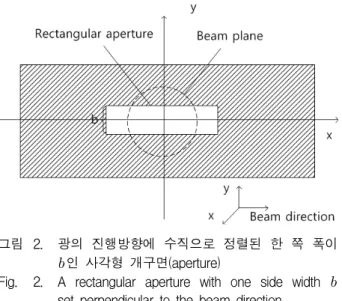
그림 2. 광의 진행방향에 수직으로 정렬된 한 쪽 폭이
인 사각형 개구면(aperture)
Fig. 2. A rectangular aperture with one side width set perpendicular to the beam direction.
to broaden and collimate the beam. The beam from the collimator can be described by Gaussian distribution approximately and it was measured using a beam profile analyser. Then the output beam was modulated by a rectangular aperture which was perpendicular to the output beam plane as shown in Fig. 2. The relationship between output beam power
and the relative displacement of the aperture center was acquired by experiment as follows. We set a rectangular aperture at the central point of the beam plane which moved with a cut movement to the beam plane in the y direction as shown in Fig. 2.
One side length of the aperture was designed to be longer than the beam diameter, and the other side was varied and denoted by .
In our experiment, a 1550 nm broadband light source (BLS) with 2 mW input power, a 1×2 coupler with 1:99 coupling ratio, a collimator with a beam diameter of 7 mm, a micro-stage with a dynamic range of 0-6 mm, and rectangular apertures with different diameter were used. We assumed that the aperture was a distance away from the central point, which is regarded as the relative displacement
. Obviously, the maximum modulated beam power which goes through the rectangular aperture is acquired when relative displacement =0 according to the property of Gaussian distribution. The measured
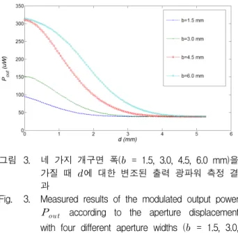
그림 3. 네 가지 개구면 폭( = 1.5, 3.0, 4.5, 6.0 mm)을 가질 때 에 대한 변조된 출력 광파워 측정 결 과
Fig. 3. Measured results of the modulated output power
according to the aperture displacement with four different aperture widths ( = 1.5, 3.0, 4.5, 6.0 mm)
results of the modulated output power according to the aperture displacement for the proposed sensor with four different aperture widths (=1.5, 3.0, 4.5, 6.0 mm) are shown in Fig. 3. The optimum interpolation curves are acquired by using the least mean square method below a nonlinearity of 0.2%.
Here the nonlinearity is defined as the highest difference between the experimental points and the interpolation curve. We find that the optimum interpolation curve with range of 0.65-2.35 mm and sensitivity of 135.4 μW/mm is acquired with aperture width of 4.5 mm.
2. Mechanical Part Analysis
In the design of our proposed sensor structure for use as an accelerometer, it is assumed that the base mounted to the structure being measured undergoes a motion of sin with amplitude and frequency . With the mass undergoing a forced vibration of , the motion of the mass relative to the base, denoted as , is defined by:
(3)
By solving the mechanical equation of resonant system:
(4)
where is the mass, is the spring constant and is the damping coefficient, the mass undergoing a forced vibration of can be described by:
sin
sin
(5)
where is a constant, and represents the phase difference of transient response and steady state response between forced vibration and base vibration, respectively.
is the attenuation coefficient and
is the resonance frequency[12].In the forced vibration system, the response of the forced vibration can be assumed to be a superposition of the transient response and the steady state response. The transient part will disappear within a short time. While, the steady state part has the same frequency with the driving source. So that we usually consider the steady state response only:
sin
(6)
The ratio of the relative displacement to the
그림 4. 여섯 가지 감쇄계수(=0.1 0.5 0.6 0.7 1.0 2.0)를 가질 때 지지기반의 진동 주파수에 따른 외부 가속도 에 대한 상대변위 의 비
Fig. 4. Ratio of the relative displacement to the external acceleration according to the base frequency with six different attenuation coefficients (=0.1 0.5 0.6 0.7 1.0 2.0).
external acceleration applied on the proof mass in steady state is[12]:
(7)
where .
As shown in Fig. 4, the largest range for acceleration detection approximately in
≤ ≤ with is analyzed[12]. Note that natural frequency here is considered as a constant. If the base frequency that we need to detect is over 0.2, the ratio of the relative displacement to external acceleration applied on the proof mass will be nonlinear, that will lead to noise in detected signals.
If the accelerometer operates at low frequency,
(8)
which shows the mechanical sensitivity of the accelerometer.
Ⅲ. Design and Feasibility Test
To show the feasibility of the proposed fiber optic vibration sensor, we designed the configuration of sensor, simulated the mechanical part of the proposed sensor using 3D FEM (Finite Element Method) based on ANSYS 10.0, and validated the calibrated output signal characteristic of the proposed fiber optic vibration sensor with the input light source power fluctuation.
1. Design of Mass-Spring Structure
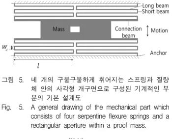
The design of the mass-spring structure is shown in Fig. 5. The open end of one spring is attached to the connection, which is stiffer than the spring, while the other end is anchored. The short beams are not free to rotate, and can move only in the direction of motion. The connection beam is stiff and can be considered as a part of the proof mass; it is designed
그림 5. 네 개의 구불구불하게 휘어지는 스프링과 질량 체 안의 사각형 개구면으로 구성된 기계적인 부 분의 기본 설계도
Fig. 5. A general drawing of the mechanical part which consists of four serpentine flexure springs and a rectangular aperture within a proof mass.
to reduce axial stress[13-14]. The total spring constant,
, is calculated by[15]:
′
∙
(9)
where ′ is the spring constant of one spring, is Young’s modulus, is the thickness of the spring, is the number of turns, and are the length and width of the long beam respectively.
2. FEM Simulation of Mechanical Part
For a better analysis of the mass-spring structure, the mechanical part was simulated by a 3D FEM based on ANSYS 10.0 as shown in Fig. 6. The same color means same displacement. The long beams of the springs were modelled by BEAM 188 and the short beams, connection beams, and proof mass were modelled by Solid 45. The springs and proof mass were made of aluminium with a Young’s modulus of
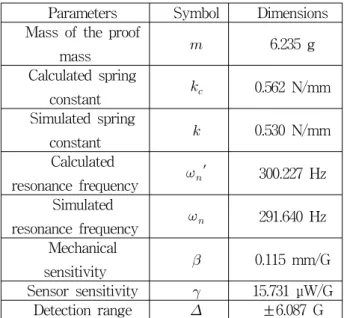
× N/m2. The total mass was 6.235 g. The size of the rectangular aperture inside the proof mass was 10 mm×4.5 mm. The length and width of the long beam were 50 mm and 1 mm, respectively. The structure was designed to have the same thickness of 1 mm. Then, using Eq. (9), the calculated spring constant and the calculated resonance frequency were found to be N/m and ′ Hz respectively as shown in Table 1. The simulated resonance frequency and the simulated
그림 6. 제안한 기계적인 부분을 ANSYS 10.0에 기반한 3차원 유한요소법으로 시뮬레이션한 결과 (동일 한 색은 동일한 변위를 의미함)
Fig. 6. 3D FEM simulation result of the proposed mechanical part based on ANSYS 10.0 (same color means same displacement).
Parameters Symbol Dimensions
Mass of the proof
mass 6.235 g
Calculated spring
constant 0.562 N/mm
Simulated spring
constant 0.530 N/mm
Calculated
resonance frequency ′ 300.227 Hz Simulated
resonance frequency 291.640 Hz Mechanical
sensitivity 0.115 mm/G
Sensor sensitivity 15.731 μW/G
Detection range ±6.087 G
표 1. 설계된 질량-스프링 구조에 대한 파라미터
Table 1. Parameters of the designed mass-spring structure.
spring constant N/mm were acquired by harmonic analysis based on ANSYS. The mechanical sensitivity mm/G was found using Eq. (8).
Note that the unit is G, where G is 9.8 m/s2. As a result, we found that the simulated results are in good agreement with the calculated results as shown in Table 1.
We have mentioned that the optimum was acquired for mm, which is why we choose a rectangular aperture 10 mm×4.5 mm for the simulation. Then by using the data measured and shown in Fig. 3, the sensitivity μW/G, the natural frequency Hz, and the detection range of the proposed sensor ±
G were found.
The simulation results of the relative displacement of the aperture according to the base acceleration with four different frequencies (0.05, 0.1, 0.2, 0.4) were shown in Fig. 7. The base undergoing resonance with different frequencies was assumed to be with base acceleration as shown in Fig. 7(a).
The response of base motion, the relative displacement of the aperture was shown in Fig. 7(b).
In order to compare the responses of different base motion, the results were normalized. We found that when the frequency of base motion was over 0.2,
그림 7. 네 가지 다른 주파수에서 지지기반이 진동하는 가속도에 따른 개구면의 정규화 상대변위 시뮬 레이션 결과 (= 291.64 Hz). (a)지지기반이 진 동하는 가속도 (b)개구면의 정규화 상대변위 (c) (b)의 스펙트럼
Fig. 7. Simulation results of the normalized relative displacement of the aperture according to the base acceleration with four different frequencies (= 291.64 Hz). (a) acceleration of base motion (b) normalized relative displacement of the aperture) (c) the spectrum of the response (b).
the responses became worse. The spectrum of the response was shown in Fig. 7(c). We have mentioned that in the forced vibration, the response of the mass motion can be assumed to be a superposition of the transient response and the steady state response, which is why there exist two frequency components in the spectrum. One frequency component is the steady state vibration frequency , while the other is
which is a fixed value for a given vibration system. The simulation results are in good agreement with the analysis results and show the feasibility of designed structure.3. Calibration of Light Source
We have mentioned that the intensity-based FOS needs a reference signal to minimize the influences of long-term aging of the source characteristics and to handle short-term fluctuations in section Ⅱ. In our light source calibration test, the input power of light source was adjusted by an attenuator. Two photodetectors, a DAQ (data acquisition) card (NI 6120) and Labview program were used for the test.
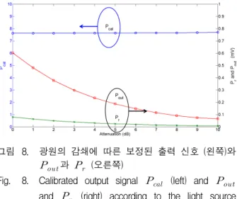
Fig. 8 shows the calibrated output signal
(left) and and (right) according to the light source attenuation. Also, Table 2 shows the mean value and standard deviation of the calibrated output
그림 8. 광원의 감쇄에 따른 보정된 출력 신호 (왼쪽)와
과 (오른쪽)
Fig. 8. Calibrated output signal (left) and
and (right) according to the light source attenuation.
Attenuation
(dB) Mean value Standard
deviation
0 7.6179 0.0549
1 7.6208 0.0718
2 7.6276 0.0908
3 7.6387 0.1214
4 7.6393 0.1398
5 7.6426 0.1964
6 7.6520 0.2408
7 7.6546 0.3279
8 7.6548 0.3932
9 7.6748 0.5001
10 7.7052 0.5543
표 2. 광원의 감쇄 증가에 따른 보정된 출력 신호
의 평균값과 표준편차
Table 2. Mean value and standard deviation of calibrated output signal with the increasing attenuation of the light source
signal with the increasing attenuation of the light source. From Fig. 8 and Table 2, we can see that the calibrated output signal shows a good stability with relative error less than 0.75% to the average of mean value. All measured data were acquired by using 10000 times of measurement. As shown in Table 2, the more attenuation of the light source shows the larger standard deviation of the calibrated output signal due to the greater influence of the floor signal for the smaller light source power. Consequently a calibrated output signal
can be used effectively to minimize the influences of long-term aging of source characteristics and to handle short-term fluctuations of light source.
Ⅳ. Conclusion
A novel intensity-based fiber optic vibration sensor using a mass-spring structure was proposed and the feasibility of the proposed sensor was presented. The mechanical part is designed and its feasibility is tested using FEM simulation program. The sensor parameters were given using the simulation and
measured results. The simulated sensor sensitivity of 15.731 μW/G and detection range of ±6.087 G are given. Using reference signal, the output signal is calibrated and shows a good stability with relative error less than 0.75% to the average of mean values.
We now focus on implementation of our proposed sensor. The sensor has the advantages of a simple structure, low cost, self-referencing, and multi-point sensing characteristic. As the collimator can be replaced by single- or multi-mode optical fibers and the mechanical part can also be miniaturized, our proposed sensor also has the potential to be made in MEMS technology.
REFERENCES
[1] E. P. Carden and P. Fanning, “Vibration Based Condition Monitoring: A Review,” Structural Health Monitoring, Vol. 3, No. 4, pp. 355-377, Dec. 2004.
[2] Y. Cao, X. L. Rong, S. J. Shao, and K. P. He,
“Present Situation and Prospects of Vibration Sensors,” CDCIEM 2012, Hunan, China, pp.
515-518, Mar. 2012.
[3] S. Saadon and O. Sidek, “A Review of Vibration-Based MEMS Piezoelectric Energy Harvesters,” Energy Conversion and Management, Vol. 52, pp. 500-504, Jan. 2011.
[4] S. Marauska, R, Jahns, H. Greve, E. Quandt, R.
Knochel and B. Wagner, “MEMS Magnetec Field Sensor Based on Magnetoelectric Composites,” Journal of Micromechanics and Microengineering, Vol. 22, No. 6, pp.
65204-65029, June 2012.
[5] T. K. Gangopadhyay, “Prospects for Fibre Bragg Gratings and Fabry-Perot Interferometers in Fibre-Optic Vibration Sensing,” Sensors and Actuators A, Vol. 113, pp. 20-38, May 2004.
[6] Y. R. Garcia, J. M. Corres and J. Goicoechea,
“Vibration Detection Using Optical Fiber Sensors,” Journal of Sensors, Vol. 2010, pp. 1-12, July 2010.
[7] A. Wada, S. Tanaka and N. Takahashi, “Optical Fiber Vibration Sensor Using FBG Fabry-Perot Interferomenter with Wavelength Scanning and Fourier Analysis,” IEEE Sensors Journal, Vol.
12, No. 1, pp. 225-229, Jan. 2012.
[8] Q. P. Liu, X. G. Qiao, J. L. Zhao, Z, A, Jia, H.
Gao and M. Shao, “Novel Fiber Bragg Grating Accelerometer Based on Diaphragm,” IEEE Sensors Journal, Vol. 12, No. 10, pp. 3000-3004, Oct. 2012.
[9] W. K. Mao and J. K. Pan, “A Novel Fiber Bragg Grating Sensing Interrogation Method Using Bidirectional Modulation of a Mach-Zehnder Electro-optical Modulator,” The Insitute of Electronics Engineers of Korea, Vol.
47, No. 7, pp. 17-22, July 2010.
[10] G. Perrone and A. Vallan, “A Low-Cost Optical Sensor for Noncontact Vibration Measurements,”
IEEE Trans. on Ins. and Measurement, Vol. 58, No. 5, pp. 1650-1656, May 2009.
[11] Y. Alayli, S. Topcu, D. Wang, R. Dib and L.
Chassagne, “Applications of A High Accuracy Optical Fiber Displacement Sensor to Vibrometry and Profilometry,” Sensors and Actuators A, Vol. 116, pp. 85-90, Oct. 2004.
[12] D. J. Inman, Engineering Vibration, Prentice Hall, 2007.
[13] A. P. Pisano and Y. H. Cho, “Mechanical Design Issues in Laterally-Driven Microstructures,”
Sensors and Actuators A: Physical, Vol. 23, pp.
1060-1064, Apr. 1990.
[14] J. Y. Chen, “Single- and Dual-axis Lateral Capacitive Accelerometers Based on CMOS-MEMS Technology,” Master Thesis, University of Oslo, Norway, Apr. 2010.
[15] W. Young and R. Budynas, Roark’s Formulas
for Stress and Strain, McGraw-Hill, 2002.
저 자 소 개 호 일(학생회원)
2008년 중국 연변대학 전기정보공 학과 학사 졸업.
2008년∼현재 전북대학교 전기공 학과 석사과정.
<주관심분야 : 광섬유 센서 및 그 응용>
김 현 호(학생회원)
2010년 전북대학교 전기공학과 학사 졸업.
2013년 전북대학교 전기공학과 석사 졸업.
2013년∼현재 전북대학교 전기공학과 박사과정.
<주관심분야 : 광섬유 센서 및 그 응용>
최 상 진(학생회원)
2011년 전북대학교 전기공학과 학사 졸업.
2011년∼현재 전북대학교 전기공 학과 석박사 통합과정.
<주관심분야 : 광섬유 센서 및 그 응용>
반 재 경(평생회원)-교신저자 1980년 연세대학교 전자공학과 학사 졸업.
1982년 연세대학교 전자공학과 석사 졸업.
1987년 연세대대학교 전자공학과 박사 졸업.
1987년∼현재 전북대학교 전기공학과 교수 2011년∼현재 전북대학교 스마트그리드연구센터 센터장
<주관심분야 : 광통신 소자 및 시스템, 광섬유 센 서 및 그 응용>