2MW급 해상용 영구자석 직접 구동형 풍력 발전기의 정상상태 특성 해석
The Steady-State Characteristic Analysis of 2MW PMSG based Direct-Drive Offshore Wind Turbine
신평호*․최정철**․유철***․김대진****․경남호*****†․고희상******
Pyungho Shin*, Jungchul Choi**, Chul Yoo***, Daejin Kim****, Namho Kyong*****†and Heesang Ko*****
(Received 10 March 2015; accepted 28 May 2015)
Abstract:In order to support various studies for assessment of onshore and offshore wind turbine system including foundations, the land-based version of 2MW PMSG direct drive wind turbine has been analyzed using HAWC2 that account for the coupled dynamics of the wind inflow, elasticity, and controls of the turbine. this work presents the steady-state response of the system and natural frequency of the first thirteen structure turbine modes as a function of wind speed. Rotor, generator speeds, pitch angle, power production, thrust force, deflections of tower and blade are compared for one case below and one case above the rated wind speed.
Key Words:Land-and sea-based wind turbines(육해상 풍력발전기), Direct drive(직접 구동형), Rated rotor speed (정격로터 속도), Permanent Magnet Synchronous Generator(영구자석 동기발전기), Pitch angle(피치각도), Peak power coefficient(최고점 출력 파워계수)
*****†경남호(교신저자) : 한국에너지기술연구원, 책임연구원 E-mail: [email protected], Tel : 064-800-2220
*신평호: 한국에너지기술연구원, 연구원
**최정철: 한국에너지기술연구원, 선임연구원
***유철: 한국에너지기술연구원, 선임연구원
*****김대진: 한국에너지기술연구원, 연구원
******고희상: 한국에너지기술연구원, 선임연구원
****†Namho Kyong(corresponding author) : Korea Institute of Energy Research, Department of Wind Energy, Senior researcher.
E-mail : [email protected], Tel : 064-800-2220
1. 서 론
기존 화석연료를 사용하여 전기를 생산하
는 방식은 온실가스 배출이 불가피하므로 풍 력 발전은 그 대안으로서 근래 20 년간 급성 장해왔다. 풍력 에너지 산업에서 해상풍력발 [논문] 한국태양에너지학회 논문집
Journal of the Korean Solar Energy Society
Vol. 35, No. 3, 2015 I S S N 1 5 9 8 - 6 4 1 1 http://dx.doi.org/10.7836/kses.2015.35.3.009
전기술은 상대적으로 새로운 분야이며 세계적 으로 넓은 바다 부지를 활용하기 위한 천해 및 심해 해역에 적절한 해상풍력 발전기술을 도 출하고자 하는 연구가 활발히 진행되고 있다.
미국 국립 재생에너지연구소인 NREL(National Renewable Energy Laboratory)을 비롯하여 일본, 유럽등지에서는 최근 깊은 바다에서 해 상풍력발전기술을 개발하려는 목적으로 개념 연구와 IEA를 통한 국제 공동 연구를 수행하 고 있다. NREL 에서는 대수심 바다에서의 풍 력 에너지를 이용하기 위하여 적합한 전형적 인 5MW 규모의 풍력발전기를 설계하고 그 사양을 제시하였다.1) NREL에서 육상 혹은 해 상에서 사용할 수 있고 고정식 혹은 부유식 해상 풍력 발전기 연구를 위해 사양이 공개된 5MW 급 풍력발전기는 가격, 효율 면까지도 고려하여 개발된 것이다. NREL 풍력발전기 모델을 기반으로 고정식 및 부유식 해상 기초 에 대한 연구는 이미 국내외 다수 기관에서 수행된바 있으며 공탄성 코드 계산 결과 검증 을 위하여 이를 사용한 바 있다.2),3) 해상 풍력 발전의 경제성은 기기 유지/보수 비용이 결정 적인 역할을 하므로 향후, 부품 수가 적고 고 장 확률이 적은 직접 구동식 풍력발전기의 사 용이 현격히 증가할 것으로 예상되고 있다.4) 기존의 국내에서 풍력 발전기 모델은 NREL 5MW, Risoe 10MW 혹은 상용 공탄성코드에 서 제시하는 모델이 사용되어져 왔으며 영구 자석 발전기 직접구동식 풍력 발전기에 대한 모델이나 제어는 제시 된 적이 없었다. 당 연 구에서는 제주 월정 해역에 설치된 2MW급 직접 구동형 영구자석형 풍력 발전기를 모델 링하기 위하여 HAWC2 을 이용한 거동 예측 을 수행하였고. 육상 풍력과 같은 고정 토목기 초를 가정하여 여러 풍속조건에 대해 정상 발 전 상태인 경우의 풍력발전기 각 부위의 반응
에 대한 결과를 얻었다. HAWC2는 다양한 외 부환경 하에서의 풍력발전기의 동적 거동을 시뮬레이션 할 수 있는 코드로서 풍력발전기 시스템의 설계 및 연구목적으로 사용되고 있 으며 일반 고정식 육상 및 해상 풍력발전기의 거 동 해석에 사용될 수 있을 뿐만 아니라 부유 식 해상풍력 발전기 거동을 해석할 수 있다.
2. Hawc2 프로그램
해상에 설치된 풍력발전기에는 바람, 제어, 공력학, 파도, 조류, 수력학 등 복잡한 힘들이 상 호작용을 한다. 이러한 힘들을 예측하고 거동 상 황을 해석적인 방법으로 모사하기 위해 HAWC2 (Horizontal Axis Wind turbine Code 2nd generation) 를 도입하여 활용하였다. HAWC2 는 풍력 발전기의 시간영역에서 거동과 하중해 석을 수행하는 공수탄성(Aero-hydro-servo-elastic code) 코드이다.5)
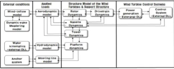
Fig. 1 Interfacing module to achieve aero-hydro-servo-elastic simulation in HAWC2
Fig.1에서 처럼 HAWC2는 각각의 모듈들이 전체 연동이 되어 상호작용을 함으로서 육·해 상 풍력발전기의 공수 탄성 시뮬레이션을 수 행한다. 이러한 특성은 파도와 바람이 시스템 의 전력생산, 하중, 운동에 영향을 미칠 수 있 기 때문에 시스템의 파도와 바람에 의한 하중 으로부터 동적 거동을 분석하는데 중요하다.
HAWC2는 계류(Mooring), 수력(Hydrodynamic)
시스템 모듈을 고려하지 않으면 육상 풍력발 전기를 모델링하는데 여전히 적용될 수 있다.
HAWC2 에서 공탄성모델은 공기역학에 대하 여 진보된 Blade Element Momentum(BEM) 이론과 구조 역학에서의 다중물체 유한 요소 형식에 기반을 두고 있다.
Fig. 2 Multibody systems[6, 7]
Fig.2에서 풍력발전기는 독립적인 구조의 몸체들로 표현을 할 수 있다. 그 몸체들은 타 워, 구동축, 허브, 날개를 이루는 여러 개의 빔 으로 구성되어 있고, 각각의 빔은 관성과 유연 성을 고려하기 위해 TB(Timoshenko Beam) 로 가정한다. 그 빔들은 구속조건에 의하여 서 로 연결이 되어있고 질량과 관성을 가진다.
Fig.2에서 다중물체 시스템이 움직일 때 관성 과 질량과 관련된 힘들이 고려되어 진다.
HAWC2에서는 물리적인 감쇄 모델이 이방 성 감쇄 특성의 모델링이 가능하도록 제시를 한다. Table. 1에서 제시한 것처럼 TB의 요소 들에 대하여 레일리 감쇄 파라미터를 6가지를 제시하였다. Mx, My, Mz 는 질량에 비례하는 감쇄이고 Kx, Ky, Kz 는 강성에 비례하는 감쇄 로 칭하여진다. 이러한 감쇄 모델은 주요 몸체 (Main body)의 x, y, z 방향으로 달리 설정이
되어 질 수 있다.8) 기존의 감쇄 모델과 다르 게, Hawc2 에서 레일리 감쇄모델은 2가지의 주요한 진동의 형상에 대하여 개별적으로 조 절이 될 수 있다. 2가지의 주요한 진동 형상은 요소의 축에 대한 비틀림(Torsion)과 2개의 횡단방향에 대한 굽힘(Bending)이다.
Rayleigh damping parameters
Factor Mx
Mass proportional damping My
Mz
Kx
Stiffness proportional damping Ky
Kz
Table. 1 Rayleigh damping used for HAWC2
Fig. 3 HAWC2 coordinate systems[9]
Fig.3 에는 HAWC2 에 대한 좌표 시스템을 보여준다. 기본 바람 방향(Wind direction)과 전체적인 기본 좌표 시스템 (Global coordinate system)이 ①로 표현된 2개의 좌표계이다. ②로 표현된 좌표 시스템은 하부구조물의 첫 번째 마디(Node)에 부여된 주요 몸체(Main body)
의 좌표계들이며 ③으로 표현된 좌표계는 날 개의 좌표계로서 공력과 구조거동을 결합하기 위하여 날개(Blade)의 뿌리에서 선단까지를 z 축, 코드 방향(Chord wise)으로는 x축, 저압 측(Suction side)으로 향하여 y축을 가지도록 정의를 하고 있다.9)
3. 직접 구동형 풍력발전기 제원
2MW급 직접구동형 풍력 발전기제원은 동적특성을 위해서 제주 월정리 해역에 설치 된 풍력발전기 모델의 정보를 근간으로 하였다.
Table. 2는 2MW 직접 구동형 풍력 발전기의 모델에 대한 제원을 보여 준다.
Rating 2MW
Rotor Orientation,
Configuration Upwind, 3blades Control Variable Speed, Collective
Pitch
Drivetrain Gearless
Rotor diameter, hub
diameter 70.64m, 2.64m
Cut in, Rated, Cut-out
Wind speed 3m/s, 13m/s, 25m/s Cut in, rated rotor speed 9 rpm, 22,5 rpm
Rated tip speed 83.21 m/s Overhang, Shaft tilt,
Precone 4.2m, 5°, 0°
Rotor mass 35,060 kg
Nacelle Mass +
Gen. stator mass 46,319 kg
Tower Mass 145,934 kg
Global coordinate
location of overall CM x: 0 m, y:-0.83 m, z: 43.5 m Table. 2 Gross properties chosen for the KIER PMSG
2MW direct drive wind turbine
Table. 2에서 도출된 풍력발전기 전체 구조 의 무게 중심은 global 좌표계를 기준으로 x:0
m, y:-0.83 m, z:43.5 m 위치하는 것을 HAWC2 계산에 의하여 도출하였다. 이 결과는 y축은 기 본바람방향으로 +이므로 y:–0.83m이면 tower top의 중심에서부터 바람방향과 반대 방향으로 무게 중심이 위치한다. 이것은 direct-drive 풍력 발전기모델의 generator가 rotor bearing 의 외형 을 둘러싸여 설치하도록 설계되었기 때문이다.
이 계산 결과는 HAWC2 의 파라미터 값을 입력할 때 tower top과 shaft의 주요 몸체에 서 concentrated mass에 해당되는 수치 값을 입력하여 얻은 계산결과이다. Concentrated mass 로 입력된 값들은 관성이 포함된 절점의 숫자, 무게중심, 질량, 관성모멘트이다. Tower top의 주요몸체의 concentrated mass 입력부 분에는 nacelle의 무게 중심 값을 입력을 하 였다. shaft의 주요몸체의 concentrated mass 입력부분에는 hub와 영구자석형 발전기의 질 량과 관성모멘트 값을 입력하였다. 1),
4. 제어 시스템
풍력발전기에서 제어는 전력을 생산하기 위하여 일반적으로 2개의 기본적인 제어시스템에 의존한 다. 첫 번째는 발전기 토크 제어(generator torque control)이고 다른 하나는 피치 제어(blade pitch control)이다. 발전기 토크 제어는 정격 구동 이전 에서 전력생산을 최대화하기 위하여 작동한다. 피 치 제어의 목적은 정격 풍속이상에서 발전기속도 를 조절하기 위한 것이다. 발전기 토크는 최적의 선단 속도 비를 유지하기 위하여 low pass filter에 의하여 걸러진 발전기 속도(generator torque)의 제 곱에 비례한다.
Table. 3 은 2MW 직접 구동형 풍력 발전기 의 모델에 대한 전체 시뮬레이션에서 제어기 부분에 입력 값을 제시하였다. 풍력발전기 모 델의 공기역학적 로터 파워, 풍속, 로터 회전
속도, 날개 피치각도, 로터 반경의 값으로 선단 속도비와 파워계수 값을 계산하였다. 계산결과 최고점 출력 파워계수(Peak power coefficient) 는 선단속도비가 7.17이면서 날개 피치 각 (blade pitch angle)이 0° 일 때 0.482의 계산 값이 도출되었다. 이러한 풍력 발전기의 구동 자료(Operational data)로부터 HAWC2 제어 기 프로그램인 HS2PID를 이용하여 region 1,2,3 에서 발전기 회전력 제어와 날개 피치 제어의 비례제어 게인(kP), 적분 게인(kI), 공 기역학적 게인 스케줄링(Aerodynamic gain scheduling), optimal Cp tracking factor의 계 산 값을 조절하였다. 따라서 Table2 에 제시 된 모든 파라미터 값들은 풍속에 따른 풍력발 전기 정상상태의 반응에 대한 전체 계산에서 제어기 부분의 입력 값으로 반영이 되었다.
Peak power coefficient 0.482 Tip speed ratio at peak
power coefficient 7.17
Rotor-collective pitch angle at peak power
coefficient 0°
Rated mechanical
power 2151 kW
Optimal Cp tracking K
factor 0.153 GNm/(rad/s)2 kP of torque controller 1.742 GNm/(rad/s) kI of torque controller 0.391 GNm/rad
kP of pitch controller 1.370 rad/(rad/s) kI of pitch controller 0.693 rad/rad Coefficient of linear term
in aerodynamic gain
scheduling 4.0245°
Maximum generator
torque 848.9kNm
Minimum pitch angle
setting 0°
Maximum pitch angle
setting 90°
Maximum absolute
blade pitch rate 4°
Table. 3 Baseline control system properties
5. 전체 시스템 고유진동수
Turbine mode
Fixed shaft Bearing shaft
Description [Hz] [Hz]
1st tower
transverse 0.4577 0.4570
1st tower
longitudinal 0.4693 0.4632
1st rotor
torsion(fixed-free) 1.0040 - 1stasymmetric
rotor flap/yaw 1.0503 1.0055 1stasymmetric
rotor flap/tilt 1.1093 1.0499
1st symmetric
rotor flap 1.4482 1.1098
1strotor edge 1 2.0724 2.0727 1strotor edge 2 2.1165 2.1145
2ndasymmetric
rotor flap/yaw 2.4707 2.4702 1st rotor
torsion(free-free) - 2.5049
2ndasymmetric
rotor flap/tilt 2.5228 2.8303 2nd symmetric
rotor edge 3.2496 3.0799
2nd symmetric
rotor flap 4.864 3.2421
Table. 4 First 13 full system natural frequency for KIER PMSG 2MW direct drive wind turbine
Table. 4에서 각각 축 고정(Fixed shaft)과 축 베어링(Bearing shaft)의 경우에 대하여 고 유진동수 모드(Mode) 별로 제시를 하였다. 고 유진동수 계산 시 날개는 최소각도인 0°으로 설정을 하였다. 축 고정의 경우는 공기역학적 감쇄(Aerodynamic damping)을 고려하지 않 았다. 축 고정의 계산 결과는 강제로 브레이크 를 걸어 고정된 회전수 발전기(Generator)의 상황에서 계산된 결과이다. 따라서 HAWC2 계산 시에 축 고정의 경우 발전기의 위치의
0 1 2 3 4 5 6 7 8 9 10 11 12 13 14 15 16 17 18 19 20 21 22 23 24 0.0
0.5 1.0 1.5 2.0
2.5 1st rotor edge 2 2nd asymmetric rotor flap/yaw 1st rotor torsion(free-free) 2nd asymmetric rotor flap/tilt 2nd symmetric rotor edge 2nd symmetric rotor flap
Rotor speed, RPM
Natural frequency, Hz
1P 3P
0 1 2 3 4 5 6 7 8 9 10 11 12 13 14 15 16 17 18 19 20 21 22 23 24 25 0
250 500 750 1000 1250 1500 1750 2000 2250 2500
Power regulation region Region 3
Rated speed:12.3 m/s Region 2
Wind Speed, m/s GenTq, kN×m
RotTorq, kN×m RotThrust, kN RotPwr, kW GenPwr, kW
Max- Cp region Region 1
0 1 2 3 4 5 6 7 8 9 10 11 12 13 14 15 16 17 18 19 20 21 22 23 24 25 0
5 10 15 20 25 30 35
Rated speed:12.3 m/s Region 2
Power regulation region Region 3
Max- Cp region Region 1
Wind Speed, m/s GenSpeed, rpm
BlPitch1, ° RotSpeed, rpm TSR, -
0 1 2 3 4 5 6 7 8 9 10 11 12 13 14 15 16 17 18 19 20 21 22 23 24 25 -0.6
-0.4 -0.2 0.0 0.2 0.4 0.6 0.8 1.0 1.2 1.4 1.6
Rated speed:12.3 m/s Power regulation region Region 3 Region 2
Max- Cp region Region 1
Wind Speed, m/s OoPDefl1, m
IPDefl1, m TTDspFA, m TTDspSS, m
후 기
본 연구는 한국에너지기술연구원의 주요사업으 로 수행한 결과입니다.(B5-2473)
Reference
1. Jonkman, S. Butterfield, W. Musial, and G.
Scott, Definition of a 5-MW Reference Wind Turbine for Offshore System Development, Technical Report NREL/TP-500-38060 pp1-63, Feb., 2009.
2. Pyungho Shin, Namho Kyong, Jungchul Choi, and Heesang Ko, A comparison of aero-hydro-elastic simulation for the load analysis of a wind turbine with monopile foundation, Proceeding of the Korea Wind Energy Association, pp128, Jun., 2014.
3. Pyungho Shin, Jungchul Choi, Chul Yoo, Namho Namho Kyong and Heesang Ko, Integrated wave and wind-induced response of the catenary moored spar-type wind turbine, Proceeding of the Korea Wind Energy Association, pp169.
Dec., 2014.
4. Latha Sethuraman, Yihan Xing, Zhen Gao, Vengatesan Venugopal, Markus Mueller, and Torgeir Maon, 5MW direct-drive generator for floating spar-buoy wind turbine: development and analysis of a fully coupled mechanical model, Proc IMechE PartA: J power and Energy 0(0) pp1-12, Jun., 2014.
5. Madjid Karimirad, Modeling aspects of a floating wind turbine for coupled wave-wind-induced dynamic analyses, Renewable Energy 53, pp.299-305, 2013.
6. Shabana, Dynamics of multibody systems, cambrige university press, pp1-11.
7. http://www.hawc2.dk/HAWC2-info/Structual -formulation.
8. Morten Hartvig Hansen, Anisotropic damping of timoshenko beam elements, Riso-R-1267(EN), pp5-6, May, 2001.
9. Larsen T. J, Hansen, A. M, How 2 HAWC2, the user’s manual, Riso-R-1597(ver. 4-5)(EN) pp22, 2014.
10. Morten H. Hansen, Anca Hansen, Torben J.
Larsen, Stig Øye, Poul SØrensen and Peter Fuglsang, Conrol design for a pitch-regulated, variable speed wind turbine, RISØ-R-1500(EN), pp31-32, Jan, 2005.
11. Kooijman, H. J. T., Lindenburg, C., Winkelaar, D., and van der Hooft, E. L., “DOWEC 6MW Pre-Design: Aero-elastic modeling of the DOWEC 6 MW pre-design in PHATAS,”
DOWEC Dutch Offshore Wind Energy Converter 1997–2003 Public Reports [CD-ROM], DOWEC 10046_009, ECN-CX--01-135, Petten, the Netherlands: Energy Research Center of the Netherlands, pp35-36, Sep., 2003.
12. Malcolm, D. J. and Hansen, A. C., WindPACT Turbine Rotor Design Study, NREL/SR500-32495, Golden, CO: National Renewable Energy Laboratory, pp29, Aug., 2002.
![Fig. 3 HAWC2 coordinate systems[9]](https://thumb-ap.123doks.com/thumbv2/123dokinfo/5326964.389286/3.892.463.767.387.869/fig-hawc-coordinate-systems.webp)
