Key Words : FSI analysis(FSI해석), Francis hydro turbine model(프랜시스 수차 모델), Numerical analysis(수치해석)
ABSTRACT
Francis turbine, as a widely used hydro turbine, is especially suited for the hydropower station with high hydraulic head.
For such turbine generator units all around the world, the crack usually comes out after a long time use and the resulted accidents may cause huge losses. Moreover, it is better for the manufacture if we know the stress of each components of the hydro turbine. In order to verify the component structure integrity, fluid-structure interaction (FSI) is an effective method to calculate the stresses in the Francis turbine components. In this study, based on the fluid-structure coupling theory, the components structural analysis of a Ns=300 [m-kW-min-1] Francis hydro turbine model was done by using CFD and static structural analysis. The results show that the stresses caused by the hydraulic forces during the normal operation are safe and the high stress on the each component is much lower than the yield strength of the material.
1. Introduction
Francis turbine, as a widely used hydro turbine, is especially suited for the hydropower station with high hydraulic head. For such turbine generator units all around the world, the crack usually comes out after a long time use and the resulted accidents may cause huge losses.
Hydropower has been a mainstream renewable energy technology for decades, and currently represents about 16 % of global electricity generation. However, while hydropower has been a steady constant in the energy supply scene, multiple energy resource combination is undergoing rapid and dramatic change.(1) Moreover, Francis turbines have been most widely used throughout the world because of its wide range of head and flow rate applications. It also provides a good efficiency near the 90% region. In most applications, it is used for high heads and flow rates.
Research on the technology of hydraulic turbine is
continuously increasing with the development of water electricity. Z. Chen et al.(2) studied the effect of runner blade loading on the performance and internal flow of a Francis hydro turbine model. There are three different blade loadings conducted to compare the internal flow characteristics and performance. The conclusion is that the front loading achieves the best efficiency in comparison with the other loadings.
W. F. Li et al.(3) studied the pressure fluctuation reducing in draft tube of Francis turbine by numerical method. Three schemes have been put forward through numerical simulations, including air admission to the draft tube, water injection to the draft tube and adding a flow deflector in the draft tube, to solve the problem of high fluctuating output of the turbine caused by the resonance between the draft tube vortex frequency and the generator natural vibration frequency.
Z. Chen et al.(4) preformed Francis turbine blade design on the basis of port area and loss analysis successfully. The best efficiency of 92.6% was achieved
* Graduate School, Department of Mechanical Engineering, Mokpo National University
** Department of Mechanical Engineering, Institute of New and Renewable Energy Technology Research, Mokpo National University
† 교신저자, E-mail : [email protected]
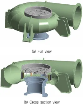
(a) Full view
(b) Cross section view
Fig. 1 The 3D modeling of the Francis hydro turbine model solid domain for structural analysis
Fig. 2 The 3D modeling of the Francis hydro turbine model runner for structural analysis
Parameters Value
Effective head H 9 m
Flow rate Q 0.34 m3/s
Rotational speed N 900 min-1
Runner outlet diameter De 350 mm
Runner blade number Zr 12
Guide vane number Zg 16
Stay vane number Zs 16
Table 1 Design specifications of francis turbine model
Fig. 3 Numerical Mesh for the CFD analysis at the center cross section plane
by this method.
Moreover, there are some new applications of the Francis turbine runner for city water supply system to recycle the energy. C. Chen et al.(5) studied a feasibility and performance studies on the flow passage shape for an inline Francis hydro turbine. The inline casing is used instead of traditional spiral casing, which has a more compact-size and is very convenient for manufacture.
However, there is rare research force on the structural analysis of a Francis hydro turbine. If we know the stress of each components of the hydro turbine, it will be very helpful for the hydro turbine manufacture.
In order to verify the runner blade structure, fluid-structure interaction (FSI) is an effective method to calculate the stresses in the Francis turbine runner.
Saeed et al.(6) found stress maxima in different parts of the runner by FSI method. Xiao et al.(7)investigated the dynamic stresses in a Francis turbine runner successfully based on FSI analysis. In this study, as the structural safety of the Francis hydro turbine is very important for the designers and manufacturers to guarantee the turbine, based on the fluid-structure coupling theory, the components structural analysis on a Ns=300 [m-kW-min-1] Francis hydro turbine model was done by using CFD and static structural analysis.
2. Francis Hydro Turbine Model and Numerical Method
2.1 Francis Hydro Turbine Model
The runner outlet diameter is De=350 mm. The number of the guide vanes are Zg=16, and the number of the blade is Zr=12. The design point of the Francis turbine model is at H=9 m for the effective head, Q=0.34 m3/s for the water flow rate and the rotational speed is N=900 min-1. The specific speed at the design point is Ns=300 [m-kW-min-1]. Fig. 1 shows the three-dimensional modeling view of the Francis hydro turbine model solid domain for the structural analysis.
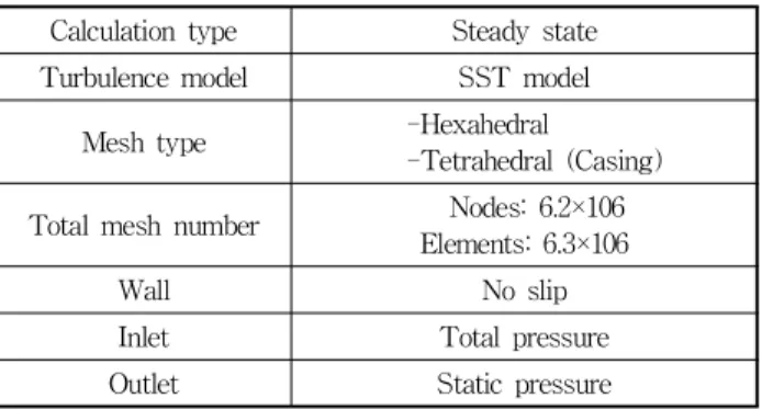
Wall No slip
Inlet Total pressure
Outlet Static pressure
Components Nodes Elements Weight [N]
Casing 2106681 1199294 4041.5
Cover 310183 193620 1175.0
Stay vane 170791 32004 114.6
Runner 588080 370373 376.3
Draft tube 343980 215295 961.3
Total 3519715 2010586 6668.9
Table 4 Mesh and components weight information
Fig. 4 Numerical mesh of the francis hydro turbine model for FSI structural analysis
Fig. 5 Boundary condition for the francis hydro turbine model FSI structural analysis
Total element number Peak stress (MPa)
1024691 40.1
2010586 44.7
4012092 45.0
Table 3 Mesh independence
Fig. 2 shows the three-dimensional modeling view of the Francis hydro turbine model runner for the structural analysis. Table 1 shows the specifications of the Francis hydro turbine model in detail.
2.2 Numerical Method
For the numerical analysis on the internal flow analysis of the Francis hydro turbine, a commercial code of ANSYS CFX(8) is adopted. Fig. 3 shows the numerical mesh for the CFD analysis at the center cross section plane. The fluid domain for the CFD analysis includes two leakage parts as shown in Fig. 3.
According to previous study(9), the shear stress transport (SST) model has been applied to the analysis, which has been well known to estimate both separation and vortex occurrence on the wall of a complicated blade shape. The operating condition maintains the head at 9 m and the flow rate range varies according to the guide vane openings. The boundary conditions
have been summarized in Table 2. For the structural analysis, the mesh dependence has been done as shown in Table 3. The peak stress with 2.0×10⁶ element number is almost similar with that with 4.0×10⁶ element number. Therefore, the final numerical mesh elements number of about 2.0×10⁶ and nodes of about 3.5×10⁶ for the total structure domain have been used as shown in Table 4. This table shows the detail for the grid number of each part of structure domain. Fig.
4 shows the numerical mesh of the Francis hydro turbine model for FSI structural analysis. The four legs and the runner shaft hole of the Francis hydro turbine model casing were set as support of fixed boundary condition as shown in Fig. 5. As the design point of the turbine operation is the key importance for the designer and manufacturer and the 100% guide
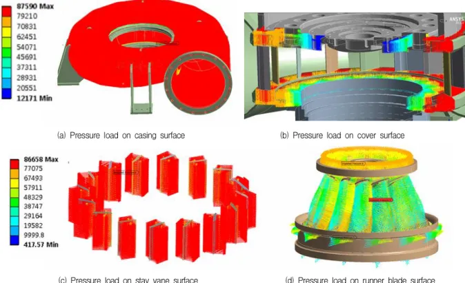
(a) Pressure load on casing surface (b) Pressure load on cover surface
(c) Pressure load on stay vane surface (d) Pressure load on runner blade surface Fig. 6 Imported each component pressure load from CFD to structure analysis
Fig. 7 Hill chart of the Francis hydro turbine model by CFD analysis
vane opening of the turbine is the design point, in this study, CFD analysis and FSI analysis at the design point were conducted. The rotational velocity was applied for the runner. Moreover, the gravity is applied for the all components. The results obtained from the CFD analysis were imported for the FSI analysis as shown in Fig. 6, which is one-way FSI analysis. The mapping rate of CFD to static structural analysis was more than 90%.
3. Results and Discussion
3.1 Performance Characteristic Curves
To obtain the hill chart of the Francis hydro turbine model, all the flow rate and rotation speed are normalized to unit flow and unit speed. The normalization of units is calculated by the following equations:
(1)
(2)
(3)
where N11 is the unit speed, Q11 is the unit flow, N is the rotational speed, D1is the diameter of runner, Q is the flow rate, H is the head of turbine, T is the torque, ω is the rotational speed of runner. The efficiency of the hydro turbine model is calculated by the Eq (3).
The hill chart of the Francis turbine model by CFD analysis is shown in Fig. 7. The efficiency in the hill chart is normalized to η/ηmax.. It can be seen that the
Fig. 8 The pressure contours from CFD analysis
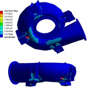
Fig. 9 The stress distribution on the casing
Fig. 10 The stress distribution on the covers
high efficiency ratio of 0.99 locates at the guide vane opening from 28 mm to 34 mm. Therefore, the operation range of this turbine with high performance is relatively wide.
3.2 FSI Analysis Results
Fig. 8 shows the pressure contours from the CFD analysis. The pressure calculated by the CFD analysis at the design flow rate condition is imported for the pressure loading on the casing, stay vane, cover and runner surface.
Fig. 9 to 12 shows the FSI analysis results for the Francis hydro turbine model. The stress on the casing is relatively higher than that on the other components.
The maximum stress of around 44.7 MPa is found on the one of the legs of the turbine casing, where is the
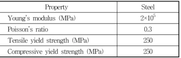
connection point between the leg supporter and the casing of the Francis hydro turbine. The material of steel is used for the casing. The property of the steel is shown in Table 5 in detail. The tensile yield strength of the steel is 250 MPa. Therefore, the stress of the casing is much lower than the yield strength of the steel, and thus the casing the safe under this condition.
The maximum stress on the cover is only around 3.2 MPa, which is very low stress for the cover part. The stress distribution on the cover is relatively uniform.
The material of the cover is steel as well. The structure of the cover is quite safe as the maximum stress on the cover is much lower than the yield strength of steel.
The stress distribution on the stay vanes is observed in Fig. 11. The stay vanes are welded on the casing to support the casing. Therefore, it is necessary to investigate the stress on the connection points between stay vanes and casing for manufacture. Maximum stress point of 27 MPa is found on the one of the stay vanes, where is the tongue part of the casing. The maximum stress locates on the trailing edge of the stay vane.
The runner of the Francis hydro turbine is the key component of the turbine unit. As the runner blade shape is very complex, the runner blade and the hub
Fig. 11 The stress distribution on the stay vanes
Fig. 12 The stress distribution on the runner
Property Steel
Young’s modulus (MPa) 2×10⁵
Poisson’s ratio 0.3
Tensile yield strength (MPa) 250 Compressive yield strength (MPa) 250
Table 5 Material properties of steel Casing Cover Stay vane Runner 0
50 100 150 200 250
Stress (Mpa)
Yield stress of steel
Fig. 13 Comparison of each component stress to the yield stress of steel
part are manufactured by the milling machine together. The shroud is welded together with runner afterward. The stress is examined that the maximum stress is only 22 MPa on the connection point between blade and hub. In comparison with the yield stress of the steel, the stress on the runner is quite lower. The runner is quite safe under the normal turbine operation condition. The summary of each component stress is shown in Fig. 13 to compare with the yield stress of steel.
4. Conclusion
In order to verify the component structure integrity, FSI is an effective method to calculate the stresses in
the Francis turbine components. The pressure calculated by CFD analysis at the design flow rate is imported for the pressure loading on the casing, stay vane, cover and runner surfaces for FSI analysis. The highest stress of 41 MPa is found on the casing component, where is connection part between the leg supporter and the casing of the Francis hydro turbine.
The stress on the casing and other components are quite lower than the yield stress of the steel, which means the turbine is quite safe under the normal turbine operation condition.
Acknowledgement
This work was supported by the New and Renewable Energy of the Korea Institute of Energy Technology Evaluation and Planning (KETEP) grant funded by the Korea government Ministry of Trade, Industry and Energy (No. 20163010060350).
References
(1) IHA central office, 2016, “2015 Hydropower Status Report,” International Hydropower Association.
(2) Chen, Z. and Choi, Y. D., 2016, “A Study on the Effect
Systems, Vol. 8, No. 3, pp. 202∼208.
(4) Chen, Z., Singh, P. M., and Choi, Y. D., 2016, “Francis Turbine Blade Design on the Basis of Port Area and Loss Analysis,” Energies, Vol. 9, No. 3, p. 164.
(5) Chen, C., Singh, P. M., Inagaki, M., and Choi, Y. D., 2015, “A Feasibility Study on the Flow Passage Shape for an Inline Francis Hydro Turbine,” The KSFM Journal of Fluid Machinery, Vol. 18, No. 2, pp. 5∼13.
Technology, Vol. 13, No. 5, pp. 587∼592.
(8) ANSYS Inc, 2013, “ANSYS CFX Documentation,” Ver.
13.
(9) Le, V., Chen, Z., and Choi, Y. D., 2016, “A Study on CFD Analysis Methods using Francis-99 Workshop Model,” The KSFM Journal of Fluid Machinery, Vol.
19, No. 5, pp. 20∼27.