2013 한국유체기계학회 학술대회 발표 논문, 2013년 11월 27-29일, 제주
◎ Original Paper
ISSN (Print): 2287-9706
10kW급 상반전 조류터빈의 설계와 성능에 관한 연구
황안둥*⋅양창조**1)†
Design and Performance Evaluation of a 10kW Scale Counter-Rotating Tidal Turbine
Anh Dung Hoang*, Chang-Jo Yang**†
Key Words : Counter-rotating, CFD, CFX, Tidal turbine, Renewable energy.
ABSTRACT
This paper aims to present the design and performance evaluation of a counter-rotating tidal turbine using CFD and to compare its performance with single rotor. The device scale is 10kW and the rotating part consists of two rotors which rotate in opposite direction. Compared with conventional single rotor, the counter-rotating system shows higher power efficiency at high stream velocity but lower efficiency at low stream velocity. The added counter-rotated rotor together helps improve the energy absorption capacity but has influence on the upstream rotor that reduces its performance. In terms of power capture, the designed counter-rotating tidal turbine is more advantageous in high speed tidal condition.
1. Introduction
The growing worldwide demand for renewable energy, coupled with apparent pool of energy within the world’s tidal currents, has led to considerable interest in tidal power development in the recent years. Among various ideas and inventions, the principle of wind turbine has brought about a trend of applying the same method to the field of ocean in order to utilize its potential natural energy resource.
The device used for capturing and converting ocean’s tidal energy to electricity is called a tidal current turbine, or tidal turbine in short. Tidal turbines are much like submerged wind turbine. They are optimally located in the sea where there are high tidal current velocities; the huge volumes of flowing water turn the blades of the turbines, thereby producing electricity.
From fundamental studies to commercial products,
many researches have been being carried out to analyze characteristics, operating performance and power efficiency of this energy conversion device.
The counter-rotating concept has been introduced lately to meet the need of power performance improvement for turbo machinery like propellers, fans, etc. including wind turbines. Since the principle of tidal turbine is relatively similar to that of wind turbine, it is possible to adopt the counter-rotating concept to the latter. Counter-rotating is the method that inputs an extra coaxial rotor at the downstream of the turbine to economize escaped energy contained in the first rotor’s wake. Thus, the total energy captured is increased theoretically. In 1919, Betz’s study stated that the highest possibly of energy fraction that can be extracted from wind turbine is around 59% of the power in the wind when the axial
* Graduate school of Mokpo National Maritime University
** Division of Marine Engineering, Mokpo National Maritime University
† 교신저자(Corresponding Author), E-mail : [email protected]
wind velocity is reduced by two-thirds crossing a single rotor disk [1]. However, in practice, wind turbines convert less than that theoretical percentage of the wind energy into electrical energy. Hence, a large amount of the potential wind energy escapes without being harnessed. In fact, there are wake effects behind a single rotor which contain a large amount of unused energy; part of this energy can be extracted further by installing a second rotor in the wake region. Since the wake behind the first rotor is rotating in the opposite direction to the rotational direction of the rotor, the second rotor should rotate in the same direction as the wake in order to effectively capture the available energy therein. Thus, a development in turbine design has been put into analysis, the contra-rotating concept, which has capability of overcoming the limitation of the efficiency of the single rotor turbine without increasing the size of the rotor; and up to now this approach is also applied and become more and more attractive in the field of tidal turbine. Betz’s theory is also studied and developed by many modern researchers and Chantharasenawong’s work is an example [2]. Thus, for recent years, several works are done to estimate the ability of counter- rotating tidal turbines, i.e. A. D. Grant’s various experiments [3], [4], D. M. O’Doherty’s computational model [5], and so on. Most of those works indicate the advantage of counter- rotating assemble in a certain condition and setup.
This paper introduces the author’s work on a computational model of counter-rotating turbine, the results of this study help contributing to the present development of tidal turbine as the potential method of tidal energy conversion to serve the future demand of renewable energy.
2. Blade Design and Simulation Setup
2.1. Blade Design
Counter-rotating tidal turbine (CRTT) is horizontal axis type, therefore turbine design should meet the requirement of generating high and optimum lift force.
Hence, choosing hydrofoil plays an important role in the very beginning of turbine blade design. Compared
to wind turbine, tidal turbine withstands much tougher operating condition. Thus, the hydrofoil in turbine design is selected from NREL thick foil family.
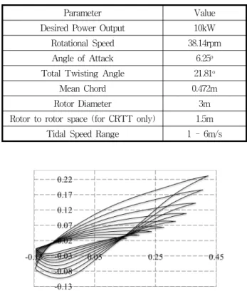
According to NREL, S823 is a thick hydrofoil designed for 3- to 10-meter diameter horizontal axis turbine (HAT), its primary objective is to improve roughness sensitiveness and lift-to-drag characteristic [6]. S823 is a proper choice for small turbine of which power output ranges from 2 to 20kW [7]. Table 1 provides design parameters of both the single rotor turbine and CRTT presented in this paper.
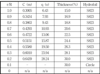
Original point data of S823 hydrofoil were input as material for the derivation of full blade. The calculation procedure is based on T. Burton’s guidance used blade element momentum theory [8]. The modelled blade’s geometrical information is summarized in Table 2 and full blade profile is viewed in Fig. 1.
The connection between root part and hub is convenient circular cylinder. Circular connection is more advantageous than the others in several aspects, i.e. ease of manufacture, adjustable blade pitch. Hub size is 0.4 meter in diameter and occupies 1/7.5 of rotor radius. For the CRTT, front and rear rotors are
Parameter Value
Desired Power Output 10kW
Rotational Speed 38.14rpm
Angle of Attack 6.25
oTotal Twisting Angle 21.81
oMean Chord 0.472m
Rotor Diameter 3m
Rotor to rotor space (for CRTT only) 1.5m Tidal Speed Range 1 - 6m/s
Table 1. Design parameters
Fig. 1 Hydrofoil profiles along the blade
r/R C (m) q (o) Thickness(%) Hydrofoil
1.0 0.3005 6.43 15.0 S823
0.9 0.3434 7.93 16.9 S823
0.8 0.3863 9.43 18.8 S823
0.7 0.4293 10.93 20.6 S823
0.6 0.4722 13.06 22.5 S823
0.5 0.5151 15.87 24.4 S823
0.4 0.5580 19.50 26.3 S823
0.3 0.6010 23.94 28.1 S823
0.2 0.6439 28.24 30.0 S823
0.1 - - 30.0 Circle
0 n/a n/a n/a n/a
Table 2. Blade geometrical information
connected to output shaft via same gearing, thus their rotational speeds are exactly the same and fixed.
2.2 Simulation Setup
Based on built geometry, three dimensional model of blade and its flow-field are rendered in modeling commercial software, ICEM CFD. In case of CRTT, two domains are generated, each one contains a rotor separately. Hexa mesh is used for numerical discretization;
it is structured mesh type that is convenient for meshing subjects with complex geometry like turbine blade. Fig. 2 shows the fine structured mesh formation of single rotor turbine domain. This meshing results in 1.1 million nodes, in case of CRTT the number of node increases to 1.6 million because of extra added rotor.
The full domain is set to rotating condition together with the rotor and has cylindrical shape as shown in Fig. 2. However, to reduce computational effort and because all three rotor blades are the same in all aspects, simulation is done on one-blade domain which is a one-third division of the full one (periodicity is 120 o ). Inlet boundary is normal speed, outlet boundary is static pressure, and opening boundary is set to “Opening Pressure and Direction”. The blades and hub are all no-slip wall boundaries. The rest of boundary conditions are the connection interphase between two domains and the rotational periodic surfaces as shown in Fig.3.
The fluid is seawater at 25 o C, turbulence model is shear stress transport (SST) with turbulence intensity is set to 5% for the whole flow-field. All simulations are done in steady state by ANSYS CFX Solver.
Fig. 2 Single rotor domain’s mesh formation
Fig. 3 CRTT simulation domain
In all simulation cases, both single rotor turbine and CRTT are tested at difference tip speed ratio (TSR) values ranging from 1 to 6, corresponded to inflow tidal speed from high to low. The relationship between tidal free stream speed and blade’s rotational speed is described by TSR and given in following equation:
R V
λ = ω
(1)
Hence, the input TSR and inflow tidal speed are set for six values as viewed in Table 3.
Turbine power efficiency is defined by power coefficient which is calculated from the output torque by the below equation:
1
32
P
C T
V A ω ρ
=
(2)
TSR 1 2 3 4 5 6 Corresponding
Tidal Speed (m/s) 6 3 2 1.5 1.2 1
Table 3. Tested tidal current speed
3. Results and Discussions
3.1 Single Rotor Blade Flow Patterns
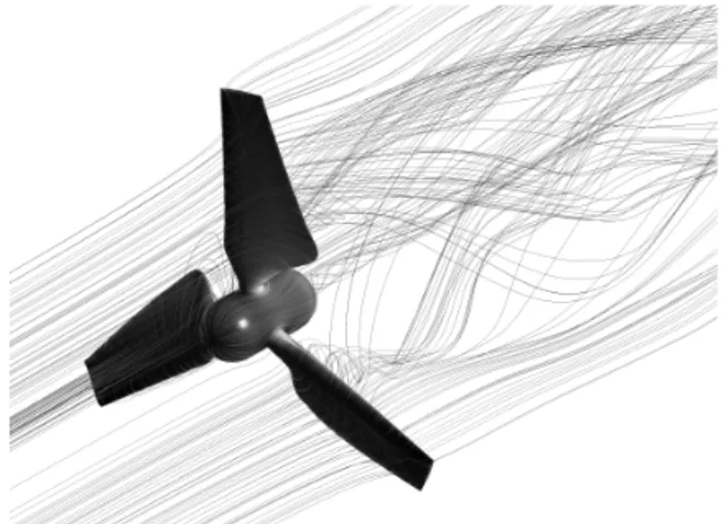
Figure 4 shows an example of flow visualization when water contacts and passes though the turbine.
The visualization renders rotor’s streamlines and wake at TSR 1. In general, there is no abnormal wake pattern. The streamlines move in the way of shedding a huge vortex at rotor’s rear like the same phenomenon in case of wind turbine. In this case, there is local vortex generated at root region of the blades. The shedding of this vortex is due to the aerodynamic profile of S823 hydrofoil under high current stream velocity.
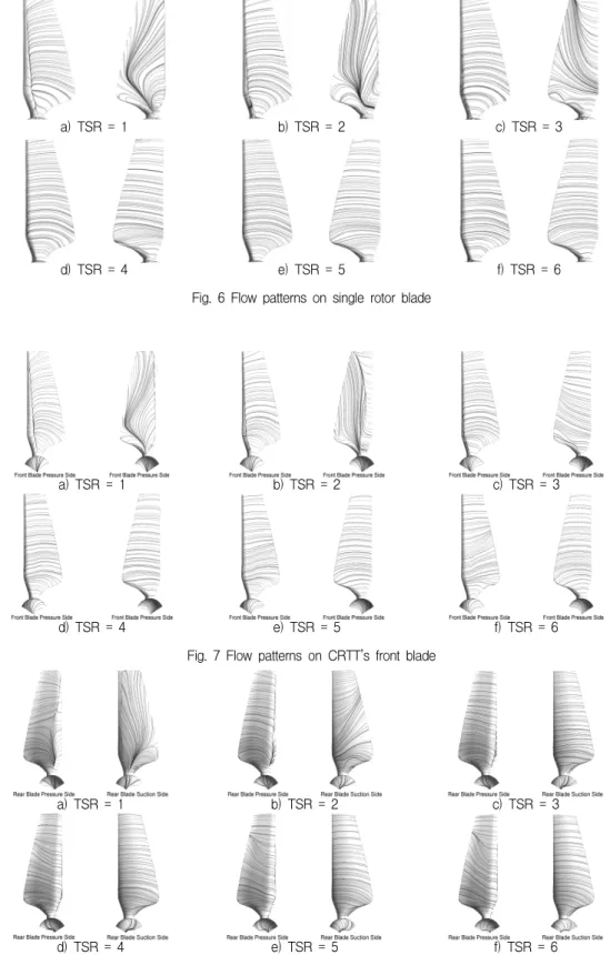
Detailed flow pattern on rotor blade at different TSRs are shown in Fig. 6. In each sub-content of this figure, the pattern illustrated on the left is on blade’s pressure side, and the one on the right is its suction side. In Fig. 6a, it is clearly seen that there is vortex at blade’s suction side; and there is difference of streamlines distribution between blade’s pressure and suction side. Normally, fluid within turbine’s wake region should flow following the blade’s rotational movement. On blade’s pressure surface, the streamlines are distributed evenly and reasonably; in contrast, the streamlines on suction surface tends to move in radial
Fig. 4 Single rotor turbine wake
direction from the root vortex toward tip. Radial flow has no effect in transferring water’s kinetic energy into rotor’s torque due to the escape of water from the wake’s core region. The main reason for this is extremely high inflow tidal speed, the inflow speed up to 6m/s is considered very high in terms of physical meaning. Thus, under such high speed flow, water is quickly detached from blades. When TSR increases up to 3 (Fig. 6c), the distribution of streamlines at blade’s pressure and suction sides become more even; and at higher TSR, from 4 to 6 (Fig. 6d, 6e and 6f), the streamlines patterns are completely well distributed.
This is due to reduced inflow tidal speed. At high inflow tidal speed (low TSR), there is also a noticeable early detachment of water flow at blade’s pressure side.
3.2 CRTT Flow Patterns
Wake visualization and flow patterns of CRTT are presented in Fig. 5, Fig. 7 and Fig. 8. Figure 7 illustrates the flow patterns of CRTT’s front rotor blade while Fig. 8 describes the flow patterns of its rear rotor blade. In these figures, pressure and suction sides of blades are indicated correspondingly.
The objective of added rotor at downstream location is to economize the escaped tidal energy available in upstream rotor’s wake. However the rotor itself also plays as an obstacle in the flow. Figure 5 illustrates CRTT wake at highest tidal stream speed. In this condition, there is appearance of complicated turbulence
Fig. 5 CRTT wake
a) TSR = 1 b) TSR = 2 c) TSR = 3
d) TSR = 4 e) TSR = 5 f) TSR = 6
effect within the inner space between the two rotors.
This effect is not advantageous and may cause local vortex and back flow that cause deficiency in both rotors’ operation. Besides, because of the wake’s
physical characteristics, water escaped from front rotor contacts the rear rotor in different angles of attack and influences the aerodynamic performance of the rear rotor blades.
a) TSR = 1 b) TSR = 2 c) TSR = 3
d) TSR = 4 e) TSR = 5 f) TSR = 6
Fig. 6 Flow patterns on single rotor blade
a) TSR = 1 b) TSR = 2 c) TSR = 3
d) TSR = 4 e) TSR = 5 f) TSR = 6
Fig. 7 Flow patterns on CRTT’s front blade
Fig. 8 Flow patterns on CRTT’s rear blade
Detailed flow patterns at TSR 1 are visualized in Fig. 7a and 8a. CRTT’s front rotor shows similar streamlines distribution compared with single rotor case; the radial flow effect exists at TSR 1 and 2. The effect vanishes at TSR 3 and higher. At rear rotor, the radial flow is generated strongly at TSR 1 but quickly ceases at TSR 2. This is due to the fact that tidal flow speed is reduced after contacting the front blade, where a portion of water’s energy was absorbed and converted to rotor’s torque. At TSR 3 and higher, both front and rear rotor shows well developed streamlines. However, at high TSR from 4 to 6 (Fig.
8d, 8e and 8f), there is tendency of flow pattern that may lead to radial flow and consequently reduces the rotor’s performance.
The design of CRTT in this paper aims to simplify manufacturing effort by using same type in shape and size for both front and rear rotors. However, the rear rotor’s performance is limited due to upstream flow and it also influences the performance of upstream rotor. Consequently, the CRTT system’s performance is limited.
3.3 Power efficiency
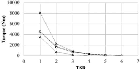
From the simulation results, torque and power coefficient data of all cases are extracted and input to graphs for comparison. Torque data are shown in Fig.
9 and power coefficient data are shown in Fig. 10. In these figures, there are four data curves; the “Single Rotor” curve presents data of single rotor turbine simulations; the “Front Rotor” and “Rear Rotor” curves in turn present data of CRTT’s front rotor and rear rotor separately; and the “CRTT” curve presents the data of the CRTT system by combining data of its front and rear rotors. As demonstrated in Fig. 9, the torque output is inversely proportional to TSR. This is reasonable since high torque can be achieved from high velocity stream. In this figure, the torque curve of single rotor turbine can be seen to coincide that of CRTT’s front rotor. However, Fig. 9 brings a closer look where it is clearly seen that the single rotor turbine has higher efficiency than CRTT’s first rotor;
and the difference becomes more and more significant at high TSR. In case of rear rotor, the torque and C P
Fig. 9 Torque generated at different TSR
Fig. 10 Power coefficient
are low throughout the speed range. Rear rotor’s performance is only noticeable at low TSR (from 1 to 3) where it has a certain contribution to CRTT’s overall performance.
In summary, at low TSR, the CRTT system shows higher performance compared to single rotor turbine case; maximum power coefficient is found at TSR 3, where C P reaches the top of 0.35. At high TSR, the CRTT’s efficiency drops dramatically, which is mainly due to the poor performance of the added extra rotor.
In single rotor turbine, maximum C P is 0.33 at TSR 4.
This value is close to D. M. O ’Doherty’s FLUENT evaluation where his turbine has C P around 0.34, but his CRTT has maximum C P up to 0.46 [5]. W. M. J.
Batten ’s work shows even higher C P , up to 0.4 for single rotor turbine [9]. Nevertheless, quantitative value of C P is only one aspect of tidal turbines, the application of CRTT and its features compared with single rotor turbine is more considerable in this paper. The installation of counter-rotated rotor at given distance in fact does influence the operation of upstream rotor and thus decreases its power efficiency.
These results are reasonable to characteristics of flow
patterns discussed above, where high efficiency is
found at cases with well-developed streamlines. In
A C
Swept area [m2]
Chord length [m]
C
Pr R T V θ r ω λ
Power coefficient Location along blade Radius [m]
Torque [Nm]
Free stream velocity [m/s]
Twisting angle [o]
Fluid density [kg/m3]
Rotational speed [rev/min]
Tip speed ratio general, counter-rotating is an approach that can be
investigated thoroughly to enhance the efficiency of marine tidal turbines, especially at high tidal current velocity regions.
4. Conclusions
This paper introduces an approach of counter- rotating application for tidal current turbines solved by CFD. To sum up, the following conclusions are given.
1) The proposed design of tidal turbine is able to capture tidal energy up to 20 - 33% of available source under normal tidal stream velocity ranging from 1 to 3m/s.
2) The CRTT is more profitable than the single rotor turbine in terms of torque absorption. However, its efficiency is not so competitive to the single rotor turbine. This is due to the complex influence between rotors that limits the system ’s performance.
3) The designed CRTT is more efficient than its single rotor turbine at low TSR. It means that this counter-rotating system is advantageous in high speed tidal streams. For low speed tidal, single rotor has acceptable power performance and more suitable than the CRTT.
The capability of the CRTT in this paper has not yet uncovered since its performance depends on various factors, i.e. distance between rotors, size and shape of the rear rotor as well as other physical phenomena.
These problems should be investigated and taken into account in future work to comprehend fully about the CRTT.
Nomenclature
REFERENCES