1. Introduction
Several studies have been done in the past for finding seismic response behavior of cylindrical and rectangular storage tanks, however, there are very few studies regarding the seismic response analysis of the horizontal and spherical storage tanks.
Like other storage structures, horizontal tanks also suffered the seismic damages on past earthquake events. Horizontal cylindrical tanks are mostly used in the industrial area with the purpose to store the chemicals and oils which are highly hazardous to the environment and flammable upon its collapse of leakage. The consequence of the failure of facilities in chemical plants will result in catastrophic damage like toxic gas diffusion and fire hazards.
Seismic analysis of the chemical plant facilities can be done by finite element analysis with different approaches that are by formulating a detailed 3D FSI model and a simplified mechanical mass-spring model. Housner(1963) formulated the simplified mass-spring model for the ground supported cylindrical tank.
The modal superposition method was adopted for seismic evaluation of the flexible cylindrical tanks by the finite element approach with experimental verification(Haroun, 1980).
Malhotra et al.(2000) have proposed a simple procedure for analyzing the vertical cylindrical storage tank with the account of impulsive and convective(sloshing) masses action in flexible tanks. The remarkable study made by Karamanos et al.(2006) formulated the expressions for calculating the dynamic properties of the spherical and horizontal storage tank system. In their study, they investigated the effect of sloshing in the horizontal and spherical tanks during earthquakes by SDOF representation of the storage system. In general, it is important to know the seismic capacity of the critical facilities over the wide range of earthquakes which can be obtained by formulating the seismic fragility curves to each of the facilities of the industrial plant. Even though a number of studies regarding seismic fragility assessment of cylindrical and rectangular tanks have been done, yet seismic fragility of the horizontal cylindrical tank has not been developed by formulating simplified finite element models.
This paper focuses on the seismic safety of the partially filled horizontal cylindrical tank. Therefore, fragility analyses were performed with the simplified model at the desired performance level. The overall study shows that seismic damage for the horizontal storage system is more susceptible in the transverse direction.
Journal of the Korea Institute for Structural Maintenance and Inspection Vol. 23, No. 7, December 2019, pp.145-151
https://doi.org/10.11112/jksmi.2019.23.7.145 pISSN 2234-6937
eISSN 2287-6979
수평원통형 저장탱크의 지진취약도 해석
나빈1, 선창호2, 김익현3*
Seismic Fragility Analysis of Ground Supported Horizontal Cylindrical Tank
Nabin Raj Chaulagain
1, Chang-Ho Sun
1, Ick-Hyun Kim
3*Abstract:
The fragility analyses for the partially filled horizontal cylindrical tank having a flexible wall were conducted to evaluate seismic performance.An equivalent simplified model with two lumped masses representing to impulsive and convective masses was used to represent the liquid storage system. This simplified model was validated by comparing its time history analysis results with the 3D FSI model results. The horizontal tank was analyzed under bi-directional excitations. Seismic fragility curves for the stability were developed in transverse and longitudinal directions. Fragility curves show that seismic damage for the horizontal storage system is more susceptible in the transverse direction.
Keywords:
Horizontal cylindrical tanks, fluid-structure interaction, simplified model, fragility curve1정회원, 울산대학교 건설환경공학부 박사과정
2정회원, 울산대학교 건설환경공학부 연구교수
3정회원, 울산대학교 건설환경공학부 교수
*Corresponding author: [email protected]
Department of Civil and Environmental Engineering, 23-309, University of Ulsan, 93, Daehak-ro, Nam-gu, Ulsan, 44610, Republic of Korea
∙본 논문에 대한 토의를 2020년 1월 31일까지 학회로 보내주시면 2020년 2월 호에 토론결과를 게재하겠습니다.
Copyright Ⓒ 2019 by The Korea Institute for Structural Maintenance and Inspection. This is an Open Access article distributed under the terms of the Creative Commons Attribution Non-Commercial License (http://creativecommons.org/licenses/by-nc/3.0)which permits unrestricted non-commercial use, distribution, and reproduction in any medium,
2. Subject
2.1 Finite element model formulation
In this study, finite element analyses were made with two different approaches, namely the FSI model and the simplified model. FSI analyses are performed in the FEM program ANSYS(Canonsbug, 2012). Since the FSI model tends to represent the exact structure, the structural components like saddles, tank wall, and contained fluid were modeled. The tank wall is modeled by four-node shell element having six degrees of freedom at each node called SHELL181. The supporting saddles were modeled by a 20-node solid element called SOLID186.
The liquid inside the tank is modeled by the FLUID80 element which has three translational degrees of freedom at each node.
These elements are suitable to model as a liquid inside the vessel without any flow rate. The behavior of the fluid is represented by the Lagrangian approach and fluid is considered as incompressible, irrotational and inviscid(Wilson and Khalvati, 1983). For the interaction between the shell and the fluid element surface- to-surface contact by the element type CONTACT174 and TARGET170 supporting the Coulomb’s friction model was used.
The simplified model is formulated with the beam element connected with rigid and convective links for impulsive and convective masses respectively. According to Eurocode 8(2006), the horizontal cylindrical tank should be analyzed for seismic actions along the longitudinal and horizontal transverse direction. The approximate hydrodynamic pressure generated by seismic actions in both longitudinal and transverse directions can be obtained by considering an equivalent rectangular tank with the same depth and volume as actual tank. Study made with this approach by converting the horizontal tank into equivalent rectangular by Carluccio et al.(2008) agreed well with the base shear component. According to Eurocode 8, the horizontal cylindrical tank can be equivalently model as a rectangular tank for the H/R range between 0.5 to 1.6. H and R are the liquid height and the radius of the horizontal tank, respectively. Therefore, in this study the simplified model is prepared by converting the horizontal tank to equivalent rectangular tank and transferring the liquid mass through convective mass and impulsive mass using elastic and rigid links respectively. The validity of the partially filled horizontal liquid storage tank is evaluated for the ground-based staged horizontal tank is presented.
2.2 Modeling
2.2.1 3D -FSI Finite Element Model
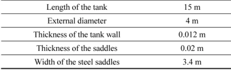
The structure analyzed in the present study is the typical ground-supported horizontal cylindrical storage tank with a volume of 188 m
3. The liquid volume in the tank is 85%. The
Fluid-structure interface
(a) Structure (FEM Modeling)
Free surface
Fluid-structure interface