Journal of Welding and Joining, Vol.34 No.4(2016) pp1-8
1. 서 론
3D printing은 CAD로 설계된 부품의 정보를 일정 한 두께의 층으로 슬라이싱한 STL파일로 변환 하여 소 재를 적층제조하는 공정을 의미하며 AM(Additive manu- facturing)이 ASTM의 공식 명칭이다
1,2). 플라스틱 소 재를 사용하는 기존의 AM은 소재의 용융점이 약 100~
400℃로 낮아 쉽게 만들 수 있었으나, 금속을 사용하 는 AM은 용융점이 약 1000~2000℃로 용융 및 적층 시키기 위하여 플라스틱 AM과는 달리 상당한 기술이 필 요하다. 지난 30년간 RP(Rapid Prototyping)라는 명칭 으로 metal AM은 꾸준히 발전해왔으며 분말베드에 고 에너지열원인 레이저와 전자빔으로 적층하는 PBF(Powder Bed Fusion)방식으로 가장먼저 개발 적용되었으며, 현 재는 소재를 직접 공급하면서 열원으로 용융․적층하는 DED(Directed Energy Deposition)방식의 metal AM
이 연구․적용되고 있다. DED 방식은 분말기반, 고체 용가재 기반으로 나뉘며, 선진국에서는 생산성이 높은 고체용가재 기반의 DED방식으로 이미 항공우주, 국방 분야에 먼저 적용하고 있다.
따라서 이 논문은 전반적인 metal AM과 용접에 의 한 AM의 연구개발 동향을 알아보고자 한다.
2. Metal AM의 분류
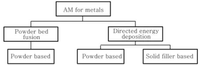
Metal AM의 분류는 Fig. 1과 같이 PBF방식과 DED
용접에 의한 Metal 3D Printing의 동향
변 재 규
*
․조 상 명**, †
*
부경대학교 대학원 신소재시스템공학과
**
부경대학교 신소재시스템공학과
Trend of Metal 3D Printing by Welding
Jae-Gyu Byun* and Sang-Myung Cho**
,
†*Dept. of Materials System Engineering, Graduate School, Pukyong National University, Busan 48513, Korea
**Dept. of Materials System Engineering, Pukyong National University, Busan 48513, Korea
†Corresponding author : [email protected]
(Received June 14, 2016 ; Revised July 13, 2016 ; Accepted July 29, 2016)
Abstract
Metal AM(Additive Manufacturing) has been steadily developed and that is classified into two method.
PBF(Powder Bed Fusion) deposited in the bed by the laser or electron beam as a heat source of the powder material and DED(Directed Energy Deposition) deposited by varied heat source of powder and solid filler material. In the developed countries has been applying high productivity process of solid filler metal based DED method to the aerospace and defense sectors. The price of the powder material is quite expensive compared to the solid filler metal. A study on DED method that is based on a solid filler metal is increasing significantly although was low accuracy and degree of freedom.
Key Words : Metal 3D printing, Additive manufacturing, Welding
ISSN 2466-2232 Online ISSN 2466-2100
AM for metals
Directed energy deposition
Solid filler based Powder based
Powder based Powder bed
fusion
Fig. 1 Classification of AM
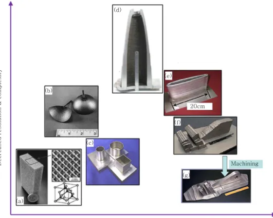
방식으로 나뉘게 된다. PBF는 분말을 소재로 베드에 분 말을 평평하게 분포시킨 후 고에너지의 레이저나 전자빔 을 선택적으로 조사 하여 소결시키거나 용융시켜 적층하 는 방법으로서 형상의 정밀도가 우수하나 생산성이 낮고 적층제품의 소결 및 용융 균일도가 좋지 못하여 제품의 강도와 충격치의 확보가 어려운 단점이 있다. DED는 소재를 직접 공급하면서 고밀도 에너지 열원으로 용융시 켜 적층하는 방법으로 용접과 유사하다. DED는 정밀도 가 낮아 후가공이 필요한 단점이 있지만, 생산성이 높고 재현반복성이 뛰어나며 강도와 충격치가 높은 장점을 가 진다. Fig. 2와 같이 제품의 생산성, 크기, 형상의 정밀도 와 해상도에 따라 다양한 metal AM방식이 사용된다
3). 이러한 DED방식은 고에너지의 레이저나 전자빔을 이용하여 동축으로 분말을 송급 및 적층하는 분말기반 DED, 용접과 유사하게 고체용가재를 송급하여 다양한 열원으로 용융 및 적층하는 고체용가재 기반 DED로 분류된다.
3. PBF process
Table 1은 metal AM 공정의 적층방식과 소재에 따 른 분류이다. PBF는 분말과 레이저열원을 기반으로 하 는 독일EOS사에서 SLS(Selective Laser Sintering) 공정을 시작으로 발전하고 있으며, 유럽의 레이저업체에 서 대부분의 공정노하우를 가지고 있다. 현재는 용융방 식의 SLM(Selective Laser Melting)공정이 주로 레 이저 업체에 의해 개발되어지고 있다.
현재 PBF공정은 장치와 소재의 개발에 이어 모니터 링 기술이 활발히 연구개발 중이다.
4. DED process 4.1 분말 기반 DED
분말을 기반으로 한 DED방식은 미국의 Optomec에
Decrease d re solution & co mp le xity
(d)
(b)
(e)
20cm
Machining (c)
(a)
(f)
(g)
Increased deposition rate & part size
Fig. 2 Comparison of surface finish and deposition rate between powder-feed/-bed and wire-feed technologies. (a)
Titanium 3D-micro framework-structure based on a diamond lattice fabricated using powder bed electron beam
melting. (b) A powder-feed-directed light fabrication of 316 stainless steel hemispherical shapes. (c) Three as con-
solidated powder-feed laser consolidation IN-625 samples with surface roughness 1–2 ㎛. (d) A large samples
fabricated by WAAM from Cranfield University. (e) 2219 Al airfoil produced by wire-feed EBF3. (f) As-de-
posited sample made by wire-feed LAM (AeroMet) with “stair stepping”surface, and g shows the sample after
surface machining
3)Material Power source Process Company Deposition rate
PBF
Powder based
Laser
SLS(Selective Laser Sintering) EOS, 3D systems,
TPM, Farsoon, etc. 0.1~0.2kg/h
DMLS(Direct Metal Laser Sintering) EOS 0.1~0.2kg/h
SLM(Selective Laser Melting)
SLM Solutions, 3D systems, Realizer, Concept laser, etc.
0.1~0.3kg/h
Electron beam EBM(Electron Beam Melting) ARCAM 0.1~0.2kg/h
DED
Laser
LENS(Laser Engineered Net Shaping) Optomec 0.1~2kg/h
DMD(Direct Metal Deposition) DM3D 0.1~2kg/h
DMT(Direct Metal Tooling) InssTek 0.1~2kg/h
CLAD(Construction Laser Additive Direct) BeAM 0.1~2kg/h
Solid filler based
Electron beam EBAM(Electron Beam Additive
Manufacturing) Sciaky ~9kg/h
GTAW,
GMAW arc WAAM(Wire Arc Additive Manufacturing) Cranfield Univ. ~4kg/h
GMAW arc DML(Direct Metal Lamination) MUTOH ~4kg/h
ADED(Arc Directed Energy Deposition) EWI ~4kg/h
Plasma arc IFF(Ion Fusion Formation) Honeywell ~3kg/h
RPD(Rapid Plasma Deposition) Norsk titanium ~6kg/h GTAW arc STAM(Super-TIG Additive Manufacturing) Super-TIG welding ~7kg/h
(a) Laser scanner
Light source(top)
Visual camera
Window of camera-view
Working plane
Feed cylinder Build cylinder
Light source(front) Light source(side)
(b)
Fig. 3 (a) Visual inspection system principle and (b) example image of deposited powder bed generated by craeghs et al.
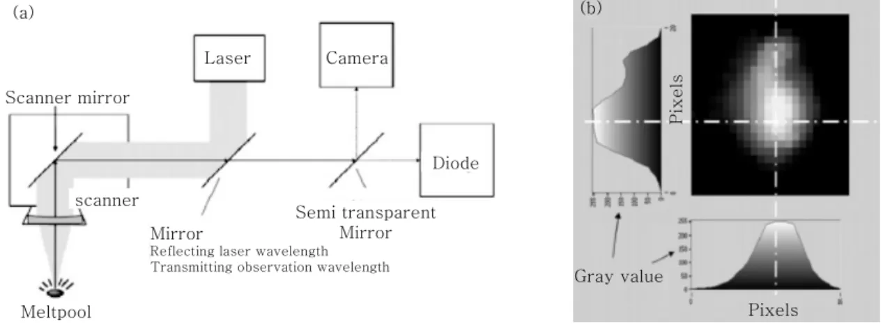
4)Laser Camera
Diode
Mirror
Reflecting laser wavelength Transmitting observation wavelength
Scanner mirror
scanner
Semi transparent Mirror
Meltpool
(a) (b)
Gray value
Pixels
Pixels
(b)
Gray value
Pixels
Pixels
Fig. 4 (a) Schematic showing arrangement of photodiode and camera and (b) an example output from the camera sys- tem showing varying intensity values (right) achieved
5)Table 1 Classification of metal AM process
서 동축으로 분말을 공급하면서 레이저를 열원으로 하 는 LENS(Laser Engineered Net Shaping)공정을 개발하여 DED의 토대를 마련하였다. 분말 기반의 DED 는 레이저업체에 따라 DMD(Direct Metal Deposition), DMT(Direct Metal Tooling)
7), CLAD(Construction Laser Additive Direct) 등 다양한 이름으로 연구 개발 중이다.
4.2 고체용가재 기반 DED
미국의 NASA Langley lab.에서 개발하여 미국 Sciaky 사로 기술이전된 EBAM(Electron Beam Additive Manufacturing)공정은 진공상태에서 고체용가재를 송 급 하여 전자빔으로 용융․적층하는 방식으로서 용착속 도가 9kg/h로 전 세계에서 가장 높은 생산속도를 가지 며 북미지역에서 연구가 활발히 이루어지고 있다
8-15). 미국의 Nottingham Univ.
16,17), Kentucky Univ.
18,19)등은 GMAW 아크열원을 사용하여 적층경로와 적층 제품 의 방향에 따른 기계적 물성을 측정하였다. 영국 Cranfield Univ.에서는 GMAW, GTAW, PAW등의 아크 열원으
로 고체용가재를 송급하는 방식인 WAAM (Wire Arc Additive Manufacturing)을 연구개발 중이다
20-25). 인 도의 IIT(Indian Institute of Technology) Bombay에 서는 CMT(Cold Metal Transfer)를 사용하여 CNC 와 결합한 metal AM장치를 연구개발 중이다
26-28). 중 국의 Harbin Institute of Technology에서는 GMAW 아크를 열원으로 비젼센서를 통한 적층 폭과 높이를 제
EB Gun
Electron beam
Prior deposit Substrate
Process coordinate
system Z
Y
X Gun
motions
Wire feeder Molten alloy
puddle
Direction of part motion Re-solidified
alloy
Fig. 6 Schematic diagram of the EBAM process
11)Deposited sample
Welding torch
Deposited sample
Welding torch
Deposited test piece
(a)
(b)
(c)
Welding torch
Fig. 7 Machine experimental set up for (a) SAM edgetek machine (b) ABB robot (c) friction stir welding machine
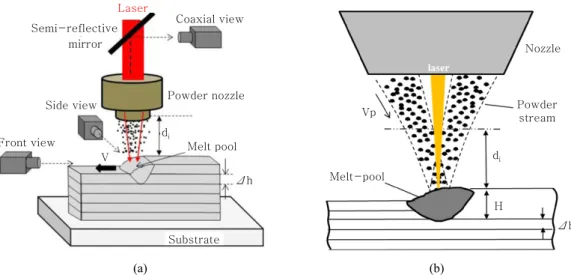
24)Laser mirror
Coaxial view
Powder nozzle
d
iMelt pool Side view
V
Δh Front view
Substrate
Nozzle
Powder stream Vp
d
iΔh H
Melt-pool Semi-reflective
(a) (b)
Fig. 5 DMD experiments - (a) Experimental set-up and associated diagnostics; (b) detail of the laser-powder-melt-pool
interaction zone (H = apparent external height of the melt-pool, Δh = additive layer height)
6)어하는 알고리즘을 만들었으며, 적층 제품의 열응력과 잔 류응력을 해석하였고
29-33), Jiaotong Univ.
34), Shanghai Univ.
35)등에서는 PAW 아크를 열원으로 공정최적화 변수를 연구개발 중이다.
일본의 Osaka Univ.에서는 GTAW의 아크 열원으 로 TiAl, TiNi, NiAl등의 이종재 적층방법에 대하여 연구하였으며
36-38)Tokyo Univ.에서는 GMAW 아크 열원을 사용한 metal AM 장치를 MUTOH사와 함께 연구 개발하였다
39). 독일EADS에서는 레이저열원에 고 체용가재를 송급하는 공정을 주로 연구개발 중이며
40,41), 레이저 열원과 GTAW열원으로 제작된 제품의 기계적 물성에 대하여 평가하였다
42). 벨기에의 Leuven Univ.에 서는 고체용가재 기반의 레이저열원 적층방식에서 GTAW 아크로 열원을 변경하여 Ti-6Al-4V 제품의 기계적 물 성을 평가하고 있다
43-45).
호주의 Wollongong Univ.에서는 GTAW와 GMAW 의 아크를 열원으로 하여 Ti-6Al-4V 제품의 적층경로 최적화 및 적층 후 가공경로 최적화에 관한 연구를 진 행 중이다
46-51).
국내에서는 KIST에서 GMAW의 아크를 열원으로 적 층 경로 최적화 및 기계적 물성 평가를 하였고
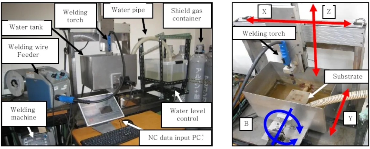
52-53), Super- TIG Welding에서 GTAW의 아크를 열원으로 C-fill-
Structured light vision sensor
Motoman Up20
Welding system
Bead image
Planning and slicing system Control cabinet
Fig. 9 Schematic diagram of the experimental set-up
32)Z
X
Y
Tungsten electrode Plasma arc welding head
Argon atmosphere
Shielding device
Welding wire
Deposited direction
Tensile specimens
Microhardness direction
Substrate Additive direction
Fig. 10 Schematic drawing of thin-wall deposited by PPAM process
35)3-axis HLM machine (only Fronius TPS 4000 is fully visible: The power
Supply and wire feeder of TPS 2700 CMT is kept outside) Two torches mounted on the spindle head Up and down positions of the torches
Fig. 8 The 3-axis hybrid layered manufacturing machine at IIT bombay
28)er
54-56)를 사용하여 용융․적층하는 공정을 개발하였고
57)
, 적층 방향에 따른 기계적 물성을 평가하였고, 공정 최적화를 연구 개발 중이다
58-61).
5. 결 론
본 리뷰 논문에서는 용접에 의한 metal AM과 관련 한 연구동향을 알아보았다. 전 세계적으로 생산성 향상
을 위하여 PBF에서 고체용가재 기반의 DED로 옮겨가 는 추세이다. 이는 Ti, Inconel과 같은 특수 분말소재 의 가격에 비해 고체용가재가 저렴하고 생산성 또한 고 체용가재 기반의 DED가 우수하기 때문이다.
이에 따라 낮은 정밀도와 자유도를 가짐에도 불구하 고 고체용가재를 기반으로 하는 DED방식의 공정에 관 한 연구가 눈에 띄게 증가하고 있었다.
References
1. ASTM, F2792-12a, Standard Terminology for Additive Manufacturing Technologies
2. Terner, Mathieu. "The Current State, Outcome and Vision of Additive Manufacturing." Journal of Welding and Joining (Vol. 33, No. 6) (2015), 12
3. Ding, Donghong, et al., Wire-feed additive manufactur- ing of metal components, technologies, developments and future interests. The International Journal of Advanced Manufacturing Technology 81.1-4 (2015), 465- 481 4. Craeghs, Tom, et al., Online quality control of selective
laser melting. Proceedings of the Solid Freeform Fabrication Symposium, Austin, TX. (2011)
5. Berumen, Sebastian, et al., Quality control of laser-and powder bed-based Additive Manufacturing (AM) technologies.
Physics procedia, 5(2010), 617-622
6. Gharbi, Myriam, et al., Influence of various process conditions on surface finishes induced by the direct met- al deposition laser technique on a Ti-6Al-4V alloy.
Journal of Materials Processing Technology 213(5) (2013), 791-800
7. Kim, Woosung, et al. "Effects and Application Cases of Injection Molds by using DED type Additive Manufacturing Process." Journal of Welding and Joining 32.4 (2014), 348-352
8. Watson, J. K., et al., Development of a prototype low- voltage electron beam freeform fabrication system. (2002)
2D path
planning Weld
setting Robot code generation
Bead modeling 3D Slicing
CAD modeling START
Input layer Hidden layer Output layer
Wire-feed rate Travel speed
Bead width Bead height
Machining
END