pISSN 1229-3008 eISSN 2287-6251
Progress in Superconductivity and Cryogenics
Vol.18, No.1, (2016), pp.19~22 http://dx.doi.org/10.9714/psac.2016.18.1.019
```
1. INTRODUCTION
CO2 emission originated in the electric power generation is increasing according to the rapid increase of world electricity demand. CO2 emission of thermal power plant account for 60% of all electric power generation, and should be decreased to realize the low-carbon society.
In feed-water system of thermal power plant, there is a problem that iron components become oxide scale and deposit on the inner surface of piping walls. Scale deposition causes decrease in heat exchange efficiency and increase in pressure loss, because thermal conductivity of the scale is about 10% of pipework material. These phenomena lead to decline in thermal power plant efficiency. However, there was no effective method for scale removal that can be used in high temperature condition of thermal power plant. We proposed a new scale removal method, High Gradient Magnetic Separation (HGMS) system using superconducting magnet. In our previous study, we succeeded to remove 98% of simulated scale in HGMS experiment under high temperature condition (200 °C) simulating thermal power plant.
One of the issues for practical use of this scale removal method is blockage of magnetic filters caused by nonuniform distribution of captured scale. It requires frequent washing of magnetic filters, which results in the
reduction of continuous operation period of the device.
Therefore, in this study, we designed the magnetic filters to equalize the magnetite quantity captured by each filter and extend the continuous operation period. We aimed to establish the design guideline of magnetic filters suitable for scale removal by means of the particle trajectory simulation and HGMS experiments.
2. THEORY OF HGMS
HGMS is a method to separate substances from fluid utilizing magnetic force. In this study, ferromagnetic filters are installed in flow channel and magnetized by external magnetic field generated by superconducting magnet. The objective particles in the magnetic field are under the influence of magnetic force, drag force, gravity, inertia force and diffusing force. Among these, gravity, inertia and diffusing force can be usually ignored because they are much smaller than magnetic and drag force in the fluid. The magnetic force FM and drag force FD acting on the separation target particles are shown in following Equation (1), (2).
M H FM 3
3 4
rP
(1)
f P
D v v
F 6rP (2)
Development of superconducting high gradient magnetic separation system for scale removal from feed-water
in thermal power plant
Saori Shibatani*,a, Motohiro Nakanishia, Nobumi Mizunoa, Fumihito Mishimaa, Yoko Akiyamaa, Hidehiko Okadab, Noriyuki Hirotab, Hideki Matsuurac, Tatsumi Maedac, Naoya Shigemotoc, and Shigehiro Nishijimaa
a Osaka University, Osaka, Japan
b National Institute for Materials Science, Tsukuba, Japan
c Shikoku Research Institute Inc., Takamatsu, Japan
(Received 15 February 2016; revised or reviewed 22 March 2016; accepted 23 March 2016)
Abstract
A Superconducting High Gradient Magnetic Separation (HGMS) system is proposed for treatment of feed-water in thermal power plant [1]. This is a method to remove the iron scale from feed-water utilizing magnetic force. One of the issues for practical use of HGMS system is to extend continuous operation period. In this study, we designed the magnetic filters by particle trajectory simulation and HGMS experiments in order to solve this problem. As a result, the quantity of magnetite captured by each filter was equalized and filter blockage was prevented. A design method of the magnetic filter was proposed which is suitable for the long-term continuous scale removal in the feed-water system of the thermal power plant.
Keywords : thermal power plant, scale removal, High Gradient Magnetic Separation (HGMS), solenoidal superconducting magnet, particle trajectory simulation
* Corresponding author:
Development of superconducting high gradient magnetic separation system for scale removal from feed-water in thermal power plant
where rp is particle radius, M is magnetization of particle, H is magnetic field intensity, η is viscosity of fluid, vf is velocity of fluid and vp is velocity of particle. Larger magnetic force and smaller drag force make it easier to remove the target particles from the fluid.
Equation (2) indicates that drag force is proportional to the viscosity of fluid. In this study, we consider the possibility of magnetic separation under high temperature condition of thermal power plant. The viscosity of water at high temperature is smaller than that at room temperature that makes drag force smaller.
3. METHODS
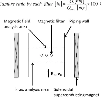
First, we analyzed magnetic field and fluid around the wire of magnetic filters by Finite Element Method (FEM) using ANSYS® Ver.10.0. Fig.1 shows the analytic model.
This model simulates the condition that magnetic filters are installed in pipework allocated in the bore of solenoidal superconducting magnet that can generate high external magnetic field. The cross-section of magnetic wires in horizontal direction of pipework are modeled as a part of magnetic filter. The fluid and magnetic field distribution were analyzed around wires arrayed at the center of flow channel as shown in the Fig.1. The interval of magnetic wire was 2.5 mm which corresponds to 10 mesh filter.
Table I shows the simulation conditions. Applied magnetic flux density was 2.0 T so that the magnetite particles as separation target and magnetic filters are saturated magnetically. Inlet fluid velocity was 0.6 m/s which is a typical value of circulation velocity of feed-water in thermal power plant where we consider to install the HGMS system.
In this study, fluid flow was analyzed under high temperature condition simulating feed-water of thermal power plant, and also under room temperature simulating experimental condition. Table II shows physical property of water at each temperature.
The magnetic force and drag force shown in Equation (1) and (2) were calculated by using these analysis results, The motion equation of magnetite particles in analysis area is shown in Equation (3).
D M F F a
m (3)
Then, we obtained trajectories of magnetite particles with time-step calculation according to the motion equation shown in Equation (3). As shown in Fig.1, calculation area was around the center of flow channel (Fig.1). The diameter of magnetite particles was 4.0 μm which is the average size of magnetite used in HGMS experiment as simulated scale. Fig.2 shows a typical result of particle trajectory simulation. The area around the wire where magnetite particles can be captured by the magnetic wire was defined as ‘particle capture radius’, rc, and was shown in Fig.2 in case the magnetite particle was flown from 3 mm upstream from the wire. Separation efficiency of each filter,
α, was derived from capture ratio, ra, calculated from rc and wire diameter, dw as defined in Equation (4), (5).
mm
d mm r r
W c a
2
(4)
raf
(5) where f is filling factor of the filter and hence the separation efficiency α depends on wire diameter and mesh number.
Qn was defined as the quantity of magnetite captured by n-th filter of magnetic separation unit which consists of magnetic filters. Qn was calculated from that of k-th filter, Qk, α and Qinlet which is initial input of magnetite (6). In addition, capture ratio by each filter was derived from Qn and total quantity of captured magnetite by all filters, Qtotal (7).
mg Q mg
Q mg Q
n
k k inlet
n
1
1
(6)
100
%
mg Q
mg filter Q
each by ratio Capture
total
n (7)
Fig. 1. Model for magnetic field and fluid analysis.
TABLE I SIMULATION CONDITION.
TABLE II
PHYSICAL PROPERTY OF WATER [2].
Temperature Viscosity coefficient Density 293 K 1.0×10⁻³ Pas 998.2 kg/m3 473 K 1.5×10⁻⁴ Pas 864.7 kg/m3
Filter material SUS430,
galvanized iron Applied magnetic flux density: B0 2.0 T
Fluid Water
Inlet velocity of fluid: V0 0.6 m/s 20
Saori Shibatani, Motohiro Nakanishi, Nobumi Mizuno, Fumihito Mishima, Yoko Akiyama, Hidehiko Okada···
Fig. 2. Typical example of the calculated particle trajectory and definition of particle capture radius.
4. RESULTS AND DISCUSSIONS 4.1 Theoretical and experimental results at room temperature
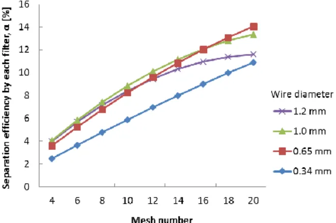
Fig.3 shows mesh number dependency of separation efficiency of each filter, α, based on results of simulation under room temperature. The separation efficiency α increases with increase of wire diameter and mesh number.
However, increase in wire diameter and mesh number results in high pressure loss of magnetic filters, because of large packing factor of filters. On the other hand, when the wire diameter is small, magnetic filters have low durability against the rapid flow of feed-water.
Considering these factors, we designed the magnetic filters in order to extend continuous operation period of the system (Table III). Mesh number of magnetic filters were systematically changed based on the results of simulation in order to eliminate blockage of inlet side filters in filter condition (b) and (c). The mesh number becomes larger in stepwise towards to outlet side. In filter condition (a), identical mesh filters were used for a comparison.
Table IV shows the results of simulation and experiments [3] conducted in these filter conditions. In the case of (a), most of magnetite were captured by inlet side filters and capture quantity became smaller toward an outlet side, so it can be said that inlet side filters are easy to be blocked. On the other hand, in the case of (b), theoretical results indicated that the uneven distribution of captured magnetite quantity by each filter was resolved. However, magnetite was intensively captured by inlet side filters in the experiment. Possible reasons for this difference between simulation and experiment are as follows: flow velocity distribution in pipework was not considered in the simulation, or magnetite particles used in the experiment were aggregated in the fluid. Therefore we enlarged the changing rate of mesh number as shown in (c). As a result, we succeeded in equalization of the deviation of magnetite capture quantity by each filter in experiment.
Fig. 3. Relationship between mesh number and separation efficiency by each filter, α in (4). Temperature of water is 293 K, filter material is 430ss.
TABLE III FILTER CONDITIONS. Filter
condition
Filter number
Mesh number
Wire
diameter Material
(a)
1~3 20
0.34 mm 430ss
4~6 20
7~9 20
10~12 20
(b)
1~3 4
1.0 mm galvanized iron
4~6 6
7~9 8
10~12 10
(c)
1~3 2
1.0 mm galvanized iron
4~6 4
7~9 6
10~12 10
TABLE IV
RESULT OF SIMULATION AND EXPERIMENTS [3].
Filter condition
Filter number
Capture ratio by each filter [%]
Simulation Experiment
(a)
1~3 45 72
20
4~6 28
7~9 17 5.7
10~12 10 2.4
(b)
1~3 24 41
4~6 28 29
7~9 27 19
10~12 22 12
(c)
1~3 13 21
4~6 22 29
7~9 25 27
10~12 28 23
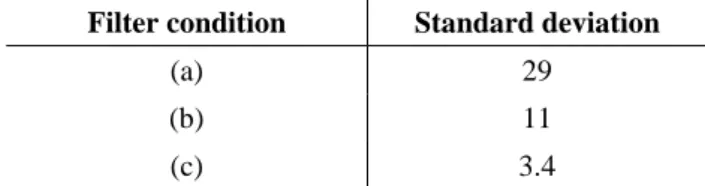
Table V shows standard deviations of captured magnetite quantity by each set of 3 filters. The standard deviation of (c) was smaller than that of (a) or (b). These results indicate that blockage of inlet side filters will be
21
Development of superconducting high gradient magnetic separation system for scale removal from feed-water in thermal power plant
TABLE V
STANDARD DEVIATIONS OF CAPTURED MAGNETITE QUANTITY BY EACH SET OF 3 FILTERS OF EACH EXPERIMENT.
Filter condition Standard deviation
(a) 29
(b) 11
(c) 3.4
prevented and continuous operation period of magnetic filters will be extended. When we use filter condition (c), continuous operation period under room temperature is expected to become 1.9 times longer than filter condition (a) calculating from the total quantity of captured magnetite.
In short, long-term operation of HGMS device for scale removal will be possible and the scale can be removed more effectively.
From these results, the possibility was shown that magnetic filters installed in HGMS devices for scale removal can be optimized by simulation and experiments.
4.2 Theoretical results at high temperature
The actual temperature of thermal power plant feed-water where we are planning to install HGMS system is about 493 K. We conducted a simulation at high temperature.
Because it is difficult to conduct an experiment and verify the magnetite capture quantity of each filter on this temperature range. Viscosity coefficient and relative density of high temperature water are different from those of room temperature water, as shown in Table II. Fig.4 shows result of simulation conducted under high temperature condition. This result indicates that it is possible to equalize the magnetite capture quantity by each filter even under high temperature and high pressure condition. In addition, separation rate was about 90% at the condition shown in Fig.4. The magnetite density of feed-water where we are planning to install the HGMS system is about 10 ppb and it is necessary to be 2~3 ppb.
Therefore, 90% would be enough value of separation rate.
From this result, it was shown that separation efficiency of magnetite is higher under high temperature condition in comparison with room temperature condition. This is because viscosity coefficient and density of water become smaller under high temperature conditions, which makes drag force smaller in comparison with room temperature conditions.
As a result, the feasibility of the HGMS device suitable for the long term scale removal in the thermal power plant feed-water system was shown.
Fig. 4. Magnetite capture ratio by each filter in (6) and mesh number of each filter. Temperature of water is 493 K, filter material is 430ss.
5. CONCLUSION
We considered to establish the design guideline of magnetic filters for scale removal by particle trajectory simulation and HGMS experiments. In this study, we succeeded in designing the magnetic filters which can be continuously operated in long-term at room temperature.
By applying this design method under high temperature and pressure condition in simulation, the feasibility was shown that the HGMS device suitable for the long-term scale removal in thermal power plant feed-water.
REFERENCES
[1] N. Mizuno, F. Mishima, Y. Akiyama, H. Okada, N.
Hirota, H. Matsuura, T. Maeda, N. Shigemoto, S.
Nishijima “Removal of iron oxide with superconducting magnet high gradient magnetic separation from feed-water in thermal plant,” IEEE Trans. Appl. Supercond., vol. 25, no. 3, Article #.
3700804, 2015.
[2] Japan Society of Thermophysical Properties:
Thermophysical Properties Handbook, 2008
[3] S. Shibatani, et al. “Study on magnetic separation device for scale removal from feed-water in thermal power plant,” IEEE Trans. Appl. Supercond., forthcoming.
22