521
Korean Circ J 2007;37:521-529 Copyright ⓒ 2007 The Korean Society of Cardiology
Multidector CT Imaging of Coronary Artery Stents:
Is This Method Ready for Use?
Jung Im Jung, MD
Department of Radiology, St. Mary’s Hospital, College of Medicine, The Catholic University of Korea, Seoul, Korea ABSTRACT
Coronary artery stenting has become the most important nonsurgical treatment for coronary artery disease. However, in-stent restenosis occurs at a relatively high rate and this problem has led to the routine use of invasive angiography for assessing stent patency. Although coronary angiography is the clinical gold standard and it is a very effective diagnostic tool for detecting such in-stent restenosis, it’s clearly an invasive procedure with its associated morbidity and mortality risks. Therefore, a noninvasive technique for detecting in-stent restenosis would be of great interest and use for follo- wing up patients after coronary angioplasty. Multidetector-row CT (MDCT) is being increasingly used for noninvasive coronary artery imaging as it has high diagnostic accuracy for detecting coronary artery stenosis in native, non-stented, coronary arteries. However, the application of MDCT to stent imaging is somewhat difficult. It is generally accepted that visualizing the in-stent lumen with using 4-slice MDCT is impossible because of the modality’s low temporal and spatial resolution. There is increased visualization of the stent lumen on 16-slice MDCT, and so in-stent restenosis can be detected in assessable stents. Yet for stents with small diameters (<3 mm) and/or thicker struts, visualization of instent stenosis remains a problem. The recently introduced 64-slice CT offers more improved spatial and temporal resolution than does 16-slice CT and this results in superior visualization of the stent lumen and in-stent restenosis.
However, although 64-slice MDCT allows for improved stent visualization, a relevant part (up to 47%) of the stent lumen is still not assessable. There are many factors that interfere with the assessment of the real stent lumen even on 64-slice CT. The metal of the stents can cause blooming artifacts that prevent the accurate interpretation of a lumen’s patency. The blooming effect is caused by a combination of partial volume averaging and beam hardening, and this results in higher CT attenuation values in the stent lumen and this enlarges the apparent size of the stent struts, thus leading to a pseudo-narrowing of the lumen. Regarding the type of stent, the gold or gold-coated stents along with the stents made of tantalum, cause the most severe artifacts, while the stainless steel and cobalt stents can be more acc- urately visualized. Cardiac motion, poor contrast filling, the oblique course of the coronary vessels and calcification may also decrease the ability to assess a stent’s lumen. To improve a stent’s visualization, numerous methods have been att- empted such as dedicated post-processing or the use of dual-source CT. However, because of its presently limited sen- sitivity and high radiation exposure, MDCT should not be used as the first-line test to screen for in-stent restenosis in asymptomatic patients. Given its high specificity and negative predictive value, MDCT might be valuable for confirming stent occlusion in symptomatic patients. Such stent evaluation should focus on the proximal coronary artery segments and on those stents with a diameter greater than 3 mm. (Korean Circ J 2007;37:521-529)
KEY WORDS: Multidetector row CT;Stents;Coronary stenosis.
Introduction
Percutaneous coronary intervention (PCI) has gained widespread acceptance as the treatment of choice for managing symptomatic coronary disease. The most im-
portant advance in the field of PCI was the introduction of coronary stent implantation in the 1990s because this lead to a reduction in both the risk of acute major complications and the incidence of restenosis, as com- pared with the risks after balloon angioplasty.1)2) While its technical success rate exceeds 95%, stent restenosis remains a clinical problem. The introduction of drug- eluting stents into clinical practice has dramatically re- duced the occurrence of restenosis compared with the use of bare metal stents.3-5) Yet even at this low rate,
Correspondence:Jung Im Jung, MD,Department of Radiology, St. Mary’s Hospital, College of Medicine, The Catholic University of Korea, Yeouido- dong, Yeongdeungpo-gu, Seoul 150-713, Korea
Tel: 82-2-3779-1277, Fax: 82-2-783-5288 E-mail: [email protected]
in the proximal segments of coronary arteries. However, metallic stents cause magnetic susceptibility artifacts that may prevent visualization of the lumen.11) Electron-beam computed tomography (CT) has been used to assess stent patency, yet assessment with this modality depends on indirect time-attenuation analysis in the vessel segments distal to the stent, but there is no actual visualization of the in-stent lumen.12)13)
Since its introduction, the multi-detector row CT (MDCT) technology for cardiac applications has continu- ously evolved. With increasing the number of detector rows, CT scanners can provide markedly improved tem- poral and spatial resolution on coronary imaging. MDCT also allows the imaging of coronary stents. There has been a dramatic increase in the number of recent investiga- tions that have evaluated coronary stents by MDCT, and it is now valid to ask: Is this method ready for real world clinical use?
The purpose of this article is to review the current status and perspective of MDCT imaging of coronary artery stents.
hancement in the vessel distal to the stent has to date been the best criterion for stent patency.14-16) However, observing distal run-off cannot be considered an absolute indicator of patency as the presence of vessel enhancement distal to a stent can also be secondary to retrograde filling.
The introduction of 16-slice MDCT made CT a much more viable modality for detecting significant in-stent restenosis, with reported sensitivity and specificity values in the range of 54-100% and 88-100% respectively.17-23) Coronary artery stent patency has been assessed with using 16-slice MDCT scanners on the basis of contrast enhancement measurements18-22) or pixel count meth- ods.23) However, for stents with small (<3 mm) diameters and/or thicker struts, visualization of in-stent stenosis remains a problem.17)20)21)
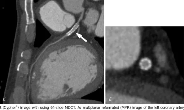
The recently introduced 64-slice MDCT scanners have improved both the temporal and spatial resolutions due to their reduced rotation time and thinner sections (0.6 mm). This modality is also likely to improve CT’s ability to access stents (Fig. 1, 2). In an in vitro study, using 64-slice MDCT resulted in superior visualization
A B
Fig. 1. Stent (Cypher®) image with using 64-slice MDCT. A: multiplanar reformated (MPR) image of the left coronary artery clearly de- monstrates the in-stent lumen and the internal enhancing vessel (arrow). B: the cross section image demonstrates the enhancing, patent stent in the vessel. MDCT: multidetector-row CT.
of the stent lumen and in-stent stenosis compared with that of 16-slice MDCT, and especially when the stent is oriented parallel to the X-ray beam.24) The recently repor- ted values for the sensitivity and specificity of detecting in-stent restenosis with using 64-slice MDCT are 89%
and 95%, respectively.25) However, although 64-slice MD- CT has allowed improved stent visualization, a relevant portion (up to 47%) of the stent lumen is still not as- sessable.26) There are many issues that interfere with the assessment of the real stent lumen, even with using 64- slice MDCT.
Issues interfering with stent assessment on Multi-detector-row CT
Mechanical factors (Beam hardening and the blooming effect, and the partial volume averaging effect)
Metallic stents cause a severe CT artifact known as the blooming effect; this is the result of beam hardening and it causes the stent struts to appear thicker than they really are.27) As a result the in-stent luminal diameter is underestimated. The energy spectrum of the X-ray beam
increases as it passes through a hyperattenuating structure because lower-energy photons are absorbed more rapi- dly than are the higher-energy photons, resulting in the beam being more intense when it reaches the dete- ctors. Calcified spots of the vessel wall near or at the outer surface of an implanted stent also contribute to beam hardening, which further erodes the assessability of the stent lumen.28) The magnitude of the artifact varies depending on the type of metal and the stent design.29) As a rule, the depiction of stents with the slimmest profile is least affected by blooming artifacts.28) Beam hardening artifacts also may be exacerbated by motion or by inappropriate selection of the reconstru- ction window.30) Conversely, blooming artifacts may be minimized by reduced motion and an optimal recon- struction window.28)30)
Another mechanical obstacle to coronary stent imaging is related to the partial volume averaging effect, and this is inherent in the cross-sectional imaging modalities and it yields a CT number that represents the average attenuation of the materials within the voxel. The partial- volume averaging may affect not only the measurement
A B
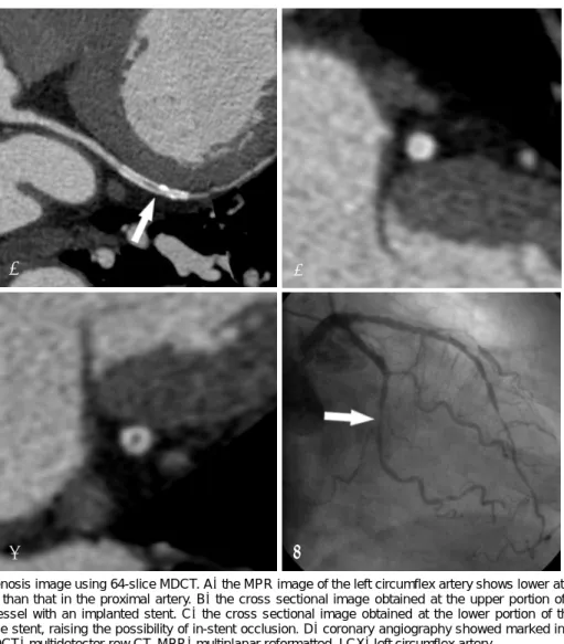
C D
Fig. 2. In-stent restenosis image using 64-slice MDCT. A: the MPR image of the left circumflex artery shows lower attenuation inside the stent lumen (arrow) than that in the proximal artery. B: the cross sectional image obtained at the upper portion of the stent shows a patent enhancing vessel with an implanted stent. C: the cross sectional image obtained at the lower portion of the stent shows low attenuation within the stent, raising the possibility of in-stent occlusion. D: coronary angiography showed marked in-stent restenosis of the LCX (arrow). MDCT: multidetector-row CT, MPR: multiplanar reformatted, LCX: left circumflex artery.
onary stents with thicker struts (Fig. 3). Uninterpretable images tend to be obtained for stents with thicker struts and/or a smaller diameter. When the lumen diameter is less than 3mm, the lumen visibility is worse.21) Regarding the type of stent, the most severe artifacts are found with tantalum, gold or gold-coated stents, or with covered stent grafts as compared with stainless steel stents.33) Maintz et al.34) recently evaluated 68 different stents in vitro with using 64-slice MDCT and they created a catalogue of the CT appearance of most of the currently available coronary stents (Table 1). They confirmed that the high variability for stent lumen visibility depended on the stent type, and this was previously reported on with using 4-slice and 16-slice CT. They also concluded that while in vivo studies will be required to verify their results, it can be assumed that a reliable evaluation of stents’ lumens in the more advantageous stent types, such as the Radius, Teneo, Symbiot or Flex standard stents, will be possible with using 64-slice MDCT.34)
Optimization of contrast enhancement
Optimal contrast enhancement is crucial for evaluating
allows estimation of the functional parameters.35) A high degree of intraluminal enhancement is recommended, especially for the investigation of stent patency in vessels with a small diameter and thus they contain less blood.
Cardiac motion
Cardiac motion is one of the most important causes of vessel non-assessability on MDCT coronary angio- graphy. The movement of coronary arteries results in blurring of the CT image and a smaller apparent stent lumen due to the partial volume effect and the metal blooming artifact. The use of high gantry rotation speeds and beta-blockers to lower the heart rate have consistently improved the interpretability of MDCT coronary angio- grams.28) The use of multisegmental reconstruction (MSR) techniques could improve the image quality in patients with a high heart rate.36-38) However, Groen et al.39)40) recently reported that MSR showed no benefit of image quality for the visualization of coronary stents at high heart rates on a moving heart phantom with using 64- slice MDCT. They concluded that lowering of the heart rate is more beneficial for image quality than using a
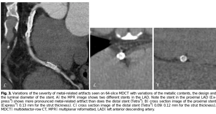
Fig. 3.Variations of the severity of metal-related artifacts seen on 64-slice MDCT with variations of the metallic contents, the design and the luminal diameter of the stent. A: the MPR image shows two different stents in the LAD. Note the stent in the proximal LAD (Ex- press®) shows more pronounced metal-related artifact than does the distal stent (Tetra®). B: cross section image of the proximal stent (Express®: 0.13 mm for the strut thickness). C: cross section image of the distal stent (Tetra®: 0.09-0.12 mm for the strut thickness).
MDCT: multidetector-row CT, MPR: multiplanar reformatted, LAD: left anterior descending artery.
A B C
Table 1.The commercial name, the manufacturer and material, the struts dimensions and the percent of the mean diameters of the visi- ble stent lumen on 64-slice CT (Modified from the tables of Maintz et al.34) with permission)
No. Name Manufacturer Material Diameter (mm)
Length (mm)
Strut thickness (mm)
Visible diameter on CT (%) 01 ACS Multilink Guidant Stainless steel 316L 33.2 25 0.127 56.70
02 Arthos-Inert AMG International Stainless steel 316L 33.2 24 0.105 63.30
03 Arthos-Pico AMG International Cobalt-chromium alloy 33.2 18 0.074 66.70
04 be-Stent 2 Medtronic Stainless steel 316L 33.2 10 0.102-0.109 53.30
05 Biodiv Ysio Abbott Vascular Devices
Stainless steel 316L+
Phosphorylcholine coating 33.2 19 0.091 63.30
06 CCSV Micro Science
Medical
Stainless steel 316L,
Tantal coating 33.2 16 0.6-0.8 60.00
07 Coroflex B. Braun Stainless steel 316L 33.2 25 0.100 63.30 08 Coroflex Blue B. Braun Cobalt-chromium
alloy (L605) 2.50 16 0.065 53.30
09 Coroflex Delta B. Braun Stainless steel 316L 3.50 16 0.120 60.00 10 Crossflex Cordis Stainless steel 316L 33.2 22 0.152 60.00 11 CSG (R010F26) Abbott Vascular Devices Stainless steel 316L 33.2 24 0.352 56.70
12 Cypher Cordis Stainless steel 316L 33.2 13 0.140 56.70
13 Driver Medtronic Cobalt-chromium alloy 33.2 18 0.097 66.70
14 Duett Guidant Stainless steel 316L 33.2 07 0.140 46.70
15 Express 2 Boston scientific Stainless steel 316L 43.2 20 0.130 50.00 16 F1 Large
(010FF12) Abbott Vascular Stainless steel 316L 33.2 12 0.090 63.30 17 F1 Medium
(009FF12) Devices Stainless steel 316L 2.75 12 0.090 63.30 18 F1 Small
(006FF16)
Abbott Vascular
Devices Stainless steel 316L 2.50 15 0.090 63.30
19 Flex AS Phytis Stainless steel 316L+
DLC coating 33.2 07 0.090 53.30
20 Flex Small (006F26)
Abbott Vascular
Devices Stainless steel 316L 2.50 26 0.090 66.70
21 Flex Standard
(010F12) Phytis Stainless steel 316L 33.2 12 0.090 70.00
22 Herculink Guidant Stainless steel 316L 43.2 18 0.102-0.109 40.00 23 Jograft Abbott Vascular
Devices
Stainless steel 316L+
PTFE-graft 33.2 09 0.091-0.124 56.70
24 Jostent Abbott Vascular Stainless steel 316L 33.2 19 0.090 56.70 25 Lekton Devices Stainless steel 316L,
Silicon-carbide coating 2.75 15 0.8-1.0 60.00 26 Liberté Boston Scientific Stainless steel 316L+PTFE 33.2 20 0.096 53.30 27 MAC AMG International Stainless steel 316L 33.2 13 0.120 63.30 28 Magic Wallstent Bostone Scientific Cobalt alloy with
titanium core (33%) 43.2 32 0.100 29 Mansfield
Coronary Stent Mansfield Tantalum 3.50 20 0.100 23.30
30 MicroStent Medtronic-AVE Stainless steel 316L 3.50 04 0.100 36.70
31 Mini Cordis Stainless steel 316L 33.2 28 0.100 56.70
32 MSM
Coronary Stent
Micro Science Medical
Stainless steel 316L,
Tantal coating 33.2 26 0.080 60.00
33 Nexus Occam International Stainless steel 316L 33.2 19 0.11-0.13 60.00 34 Nexus 2 Occam International Stainless steel 316L 33.2 15 0.11-0.13 66.70 35 NIR Primo Bostone Scientific Stainless steel 316L 33.2 32 0.091-0.124 56.70 36 NIR Royal Bostone Scientific Stainless steel 316LS+
gold coating 33.2 25 0.140 33.00
37 NIR Royal Adv Bostone Scientific Stainless steel 316LS+
gold coating 3.50 15 0.110 43.30
38 Palmaz Cordis Stainless steel 316L 33.2 14 0.07-0.095 53.30 39 Palmaz-Crown Cordis Stainless steel 316L 33.2 22 0.091 53.30
MSR technique. They also reported that in order to reduce blurring, it is more efficient to reduce the heart rate than to increase the temporal resolution.40)
Anatomical factors
The coronary arteries typically have an oblique course and they are often assessed from multiplanar reformats of the axial images. Therefore, all the stents are positioned at two different angles towards the z-axis of the MDCT scanner in order to simulate different scenarios regarding the spatial resolution along the z-axis.26) Mahnken et al. 31) have investigated a small series of different stents at ori- entations of 0˚, 45˚ and 90˚ toward the z-axis with using 16-slice CT, and they found that 0˚ was the most advan- tageous orientation. This may be the most likely orien- tation of a stent in the mid-segment of the right coronary
artery. Stents in other vessels have decreased spatial resolution along the z-axis, which indicates that the as- sessable inner stent lumen is decreased. However, with the thinner slices of 64-slice CT, the orientation of 90˚
toward the z-axis could lead to better performance.24) Another patient factor that might limit proper assess- ment of stent lumens, as well as the native coronary artery lumens, is severe calcification, and this should also be mentioned (Fig. 4). Ohnuki et al.23) evaluated coronary in-stent stenosis on 16-slice MDCT. Of the 20 lesions, two cases were misinterpreted due to calcification. Because of the calcification artifact, it is difficult to identify con- trast in the lumen. Any calcification in the proximal po- rtion of the left anterior descending artery is most likely to be severe and it is most influential on the assessability of the stents implanted in segment #6.21) However, as
47 Sito Stents Sitomed Stainless steel 316L 2.5 28 0.100 50.00
48 Sonic Bx Cordis Stainless steel 316L 2.5 18 0.140 46.70
49 Symbiot Boston Scientific Nitinol 43. 20 0.110 70.00
50 Syncro Sorin Biomedica Stainless steel 316L+carbon
coating+2 Platinum markers 33. 19 0.075 53.30 51 Tantal Abbott Vascular
Devices Tantalum-based alloy 3.5 05 0.080 30.00
52 Tantal Sandwich Abbott Vascular Devices
316L (inside), Ta
(intermediate), 316L (outside) 33. 18 0.070 46.70 53 Taxus Boston Scientific Stainless steel 316L 3.5 12 0.130 56.70 54 Tecnic Sorin Biomedica Stainless steel 316L+carbone
coating+2 Platinum markers 33. 19 0.075 53.30 55 Tenax-complete Biotronik Stainless steel 316L 3.5 15 0.080 66.70 56 Tenax-XR Biotronik Stainless steel 316L, gold markers 33. 15 0.080 63.30
57 Teneo Biotronik Stainless steel 316L 43. 10 0.080 70.00
58 Tetra Guidant Stainless steel 316L 33. 13 0.09-0.12 53.30
59 Tristar Guidant Stainless steel 316L 43. 18 0.102-0.109 53.30
60 Tsunami Terumo Stainless steel 316L 33. 30 0.080 56.70
61 Tsunami Gold Terumo Stainless steel 316L 33. 10 0.080 60.00
62 Ultra Guidant Stainless steel 316L 3.5 18 0.128 53.30
63 Velocity Bx Cordis Stainless steel 316L 33. 18 0.140 60.00
64 V-Flex Plus Cook Stainless steel 316L 33. 12 0.069 56.70
65 Vision Guidant Cobalt-chromium alloy 33. 15 0.810 66.70
66 Wallstent Boston Scientific Stainless steel 316L 53. 35 0.100 63.30
67 Wiktor Medtronic Tantalum 3.5 30 0.064 03.30
68 Zeta Guidant Stainless steel 316L 33. 18 0.09-0.12 53.30
the severity and distribution of calcification are not un- iform, these factors affect every stent in the other seg- ments of the coronary arteries that have calcification and so this is considered to be one of the limitations of the currently available MDCT.
Perspective
How to overcome the limitations ofMultidetector-row CT for the imaging of coronary stents
Dedicated edge-enhancing convolution kerne
Post-processing is an important part of lumen visua- lization of a coronary stent. An edge-enhancing, high- spatial-resolution kernel for reconstruction yields fewer blooming artifacts and less artificial lumen narrowing, and the intraluminal attenuation changes caused by such artifacts would therefore be minimized.41-44) Maintz et al.41) reported an average 23% increase in the visible lumen diameter and a mean reduction of the intraluminal att- enuation of roughly 30% when they used the edge-enh- ancing, high-spatial resolution kernel (B45f convolutional kernel). Mahnken et al.42) found significantly smaller ar- tificial lumen narrowing and lower intraluminal atten- uation when they used a B45f convolutional kernel, as compared to the smoother B30f kernel. While the B45f convolution kernel is optimized to reduce the blooming artifacts that occur at the edges of structures that have high attenuation values, such as calcified plaques or me- tallic structures, a significant increase in image noise must be accepted as a trade-off, although this reduces the overall image quality and hampers the delineation of small low-contrast structures.41-44)
Stents
As was discussed above, the most severe artifacts are found with tantalum, gold or gold-coated stents, or with covered stents grafts as compared with stainless steel st- ents. Stents with lesser artifacts should be selected when follow up is planned. In the future, the development of CT transparent stents or biodegradable stents may create optimal conditions for non-invasive post-implantation follow-up with using MDCT.
Dual-source spiral CT
Residual cardiac motion has a role in increasing the metal-related artifacts such as beam hardening and partial volume averaging effects. Dual-source spiral CT (DSCT) provides a temporal resolution of 83 milliseconds (165 mi- lliseconds on 64-slice MDCT). Lell et al.45) recently ev- aluated coronary stents and stenoses at different heart rates in vitro. They concluded that the depiction of coro- nary stents with DSCT is possible across a large range of simulated heart rates (50-120 bpm) without incurring motion artifacts. The overall measurement errors of the in-stent diameter with using DSCT were markedly smaller than those reported for 16-slice MDCT and they were smaller than those reported for 64-slice MDCT. Although larger clinical studies will be necessary to establish the accuracy of DSCT for assessing the degree of coronary artery stenosis in vivo, the preliminary results seems to be quite promising.
Conclusion
MDCT has recently emerged as a noninvasive method for evaluating coronary stents. Because of its presently
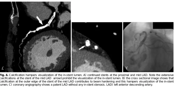
Fig. 4. Calcification hampers visualization of the in-stent lumen. A: continued stents at the proximal and mid LAD. Note the extensive calcifications at the stent of the mid LAD (arrow) prohibit the visualization of the in-stent lumen. B: the cross sectional image shows that calcification at the outer edge of the stent of the mid LAD contributes to beam hardening and this hampers visualization of the in-stent lumen. C: coronary angiography shows a patent LAD without any in-stent stenosis. LAD: left anterior descending artery.
A B C
needed in the future to optimize the utility of MDCT for assessing the lumens in stents and in the coronary arteries.
Acknowledgments
I want to thank Yun Seok Choi, MD. for his kind help in the preparation of the manuscript. Also I wish to thank Bonnie Hami, MA (USA) for her editorial assistance with the preparation of the manuscript.
REFERENCES
1) Serruys PW, de Jaegere P, Kiemenenij F, et al. A comparison of balloon-expandable-stent implantation with balloon angioplasty in patients with coronary artery disease. N Engl J Med 1994;331:
489-95.
2) Fischman DL, Leon MB, Baim DS, et al. A randomized compa- rison of coronary-stent placement and balloon angioplasty in the treatment of coronary artery disease. N Engl J Med 1994;331:
496-501.
3) Moses JW, Leon MB, Popma JJ, et al. Sirolimus-eluting stents versus standard stents in patients with stenosis in a native coronary artery. N Engl J Med 2003;349:1315-23.
4) Hong YJ, Jeong MH. New drug-eluting stents. Korean Circ J 2005;35:197-205.
5) Whang Y, Kim H, Kim K, et al. The efficacy of drug eluting stents on restenosis reduction in small coronary arteries. Korean Circ J 2006;36:450-7.
6) Park SH, Hong GR, Seo HS, Tahk SJ. Stent thrombosis after su- ccessful drug-eluting stent implantation. Korean Circ J 2005;35:
163-71.
7) Lim DS. Coronary restenosis after drug-eluting stent implantation in diabetic patients. Korean Circ J 2006;36:1-7.
8) Lee CW, Park S. Predictive factors for restenosis after drug-eluting stent implantation. Korean Circ J 2007;37:97-102.
9) Scanlon PJ, Faxon DP, Audet AM, et al. ACC/AHA guidelines for coronary angiography: a report of the American College of Car- diology/American Heart Association Task Force on practice gui- delines (Committee on Coronary Angiography): developed in coll- aboration with the Society for Cardiac Angiography and Inter- ventions. J Am Coll Cardiol 1999;33:1756-824.
10) Kim WY, Danias PG, Stuber M, et al. Coronary magnetic reson- ance angiography for the detection of coronary stenoses. N Engl J Med 2001;345:1863-9.
11) Hug J, Nagel E, Bornstedt A, Schnackenberg B, Oswald H, Fleck E. Coronary arterial stents: safety and artifacts during MR imag- ing. Radiology 2000;216:781-7.
12) Pump H, Mohlenkamp S, Sehnert CA, et al. Coronary arterial stent patency: assessment with electron-beam CT. Radiology 2000;
214:447-52.
13) Knollmann FD, Moller J, Gebert A, Bethge C, Felix R. Assessment
J Cardiol 2004;94:427-30.
18) Cademartiri F, Mollet N, Lemos PA, et al. Usefulness of multislice computed tomographic coronary angiography to assess in-stent restenosis. Am J Cardiol 2005;96:799-802.
19) Gilard M, Cornily JC, Rioufol G, et al. Noninvasive assessment of left main coronary stent patency with 16-slice computed tom- ography. Am J Cardiol 2005;95:110-2.
20) Gilard M, Cornily JC, Pennec PY, et al. Assessment of coronary artery stenosis by 16-slice computed tomography. Heart 2006;92:
58-61.
21) Kitagawa T, Fujii T, Tomohiro Y, et al. Noninvasive assessment of coronary stents in patients by 16-slice computed tomography.
Int J Cardiol 2006;109:188-94.
22) Hong C, Chrysanti GS, Woodard PK, Bae KT. Coronary artery stent patency assessed with in-stent contrast enhancement measured at multi-detector row CT angiography: initial experience. Radiology 2004;233:286-91.
23) Ohnuki K, Yoshida S, Ohta M, et al. New diagnostic technique in multi-slice computed tomography for in-stent restenosis: pixel count method. Int J Cardiol 2006;108:251-8.
24) Seifarth H, Ozgun M, Raupach R, et al. 64-versus 16-slice CT angiography for coronary artery stent assessment: in vitro experi- ence. Invest Radiol 2006;41:22-7.
25) Oncel D, Oncel G, Karaca M. Coronary stent patency and in- stent restenosis: determination with 64-section multidetector CT coronary angiography-initial experience. Radiology 2007;242:
403-9.
26) Mahnken AH, Muhlenbruch G, Seyfarth T, et al. 64-slice computed tomography assessment of coronary artery stents: a phantom study.
Acta Radiol 2006;47:36-42.
27) Nieman K, Cademartiri F, Raaijmakers R, Pattynama P, de Feyter P. Noninvasive angiographic evaluation of coronary stents with multi-slice spiral computed tomography. Herz 2003;28:136-42.
28) Pugliese F, Cademartiri F, van Mieghem C, et al. Multidetector CT for visualization of coronary stents. Radiographics 2006;26:887- 904.
29) Maintz D, Juergens KU, Wichter T, Grude MJ, Heindel W, Fis- chbach R. Imaging of coronary artery stents using multislice com- puted tomography: in vitro evaluation. Eur Radiol 2003;13:830-5.
30) Choi HS, Choi BW, Choe KO, et al. Pitfalls, artifacts, and remidies in multi-detector row CT coronary angiography. Radiographics 2004;24:787-800.
31) Mahnken AH, Seyfarth T, Flohr T, et al. Flat-panel detector com- puted tomography for the assessment of coronary artery stents:
phantom study in comparison with 16-slice spiral computed to- mography. Invest Radiol 2005;40:8-13.
32) Nieman K, Cademartiri F, Lemos PA, Raaijmakers R, Pattynama PM, de Feyter PJ. Reliable noninvasive coronary angiography with fast submillimeter multislice spiral computed tomography.
Circulation 2002;106:2051-4.
33) Mahnken AH, Buecker A, Wildberger AJ, et al. Coronary artery stents in multislice computed tomography: in vitro artifact evaluation.
Invest Radiol 2004;39:27-33.
34) Maintz D, Seifarth H, Raupach R, et al. 64-slice multidetector coronary CT angiography: in vitro evaluation of 68 different stents.
Eur Radiol 2006;16:818-26.
35) Mahnken AH, Muhlenbruch G, Gunther RW, Wildberger JE. Car- diac CT: coronary arteries and beyond. Eur Radiol 2007;17:
994-1008.
36) Flohr T, Kuttner A, Bruder H, et al. Performance evaluation of a multi-slice CT system with 16-slice detector and increased gantry rotation speed for isotropic submillimeter imaging of the heart.
Herz 2003;28:7-19.
37) Greuter MJ, Dorgelo J, Tukker WG, Oudkerk M. Study on motion artifacts in coronary arteries with an anthropomorphic moving heart phantom on an ECG-gated multidetector computed tomo- graphy unit. Eur Radiol 2005;15:995-1007.
38) Juergens KU, Maintz D, Grude M, et al. Multi-detector row com- puted tomography of the heart: dose a multisegment reconstruc- tion algorithm improve left ventricular volume measurements?
Eur Radiol 2005;15:111-7.
39) Groen JM, Greuter MJ, van Ooijen PM, Willems TP, Oudkerk M.
Initial results on visualization of coronary artery stents at multiple
heart rates on a moving heart phantom using 64-MDCT. J Comput Assist Tomogr 2006;30:812-7.
40) Groen JM, Greuter MJ, van Ooijen PM, Oudkerk M. A new app- roach to the assessment of lumen visibility of coronary artery stent at various heart rates using 64-slice MDCT. Eur Radiol 2007;
17:1879-84.
41) Maintz D, Seifarth H, Flohr T, et al. Improved coronary artery stent visualization and in-stent stenosis detection using 16-slice co- mputed tomography and dedicated image reconstruction techni- que. Invest Radiol 2003;38:790-5.
42) Mahnken AH, Buecker A, Wildberger JE, et al. Coronary artery stents in multislice computed tomography: in vitro artifact evaluation.
Invest Radiol 2004;39:27-33.
43) Seifarth H, Raupach R, Schaller S, et al. Assessment of coronary artery stents using 16-slice MDCT angiography: evaluation of a dedicated reconstruction kernel and a noise reduction filter. Eur Radiol 2005;15:721-6.
44) Schepis T, Koepfli P, Leschka S, et al. Coronary artery stent ge- ometry and in-stent contrast attenuation with 64-slice computed tomography. Eur Radiol 2007;17:1464-73.
45) Lell MM, Panknin C, Saleh R, et al. Evaluation of coronary stents and stenoses at different heart rates with dual source spiral CT (DSCT). Invest Radiol 2007;42:536-41.