한국추진공학회 2010년도 추계학술대회 논문집 pp.105~110 2010 KSPE Fall Conference
충격파 발생기를 적용한 짧은 초음속 이젝터에 관한 연구
Vincent Lijo,* ․ 김희동*†
A Study of short supersonic ejector with shock generators
Vincent Lijo* ․ Heuy Dong Kim*†
ABSTRACT
Supersonic ejectors are simple mechanical components, which generally perform mixing and recompression of two fluid streams. Ejectors have found many applications in engineering. In aerospace engineering, they are used for high altitude testing (HAT) of a propulsion system by reducing the pressure of a test chamber. It is composed of three major sections: a vacuum test chamber, a propulsive nozzle, and a supersonic exhaust diffuser (SED). This paper aims at the improvement in HAT facility by focusing attention on the vertical firing rocket test stand with shock generators. Shock generators are mounted inside the SED for improving the pressure recovery. The results clearly showed that the performance of the ejector-diffuser system was improved with the addition of shock generators. The improvement comes in the form of reduction of the starting pressure ratio and the vertical height of test stand. It is also shown that shock generators are useful in reducing the total pressure loss in the SED.
Key Words : Compressible Flow(압축성 유동), Internal Flow(내부 유동), Ejector(이젝터), Mach Number(마하수)
† School of Mechanical Engineering, Andong National University, Korea
E-mail: [email protected]
* School of Mechanical Engineering, Andong National University, Korea
NOMENCLATURE D ‐diameter of diffuser L ‐length of diffuser
M ‐Mach number
Pa ‐ambient pressure Pc ‐cell pressure
P0 ‐engine total pressure
T ‐temperature
SED ‐supersonic exhaust diffuser 1. Introduction
The ejector systems can be largely classified into three major categories depending on its functions, such as a compressor, a fluid transport device and a vacuum pump. As a compressor, the ejector compresses the secondary low‐pressure stream utilizing the high‐pressure primary. The ejector facilitates
the dragging and carrying of the secondary stream along with the primary stream when it is employed for fluid transportation. Often it is used to create high‐vacuum levels in the secondary chamber, such as those required in a high‐altitude test (HAT) facility, by dragging mass from the secondary chamber. In such a facility, the rocket motor is placed inside the secondary chamber, and the ejector is self‐pumping with hot exhaust gas from the rocket nozzle.
As modern rocket engines have to deliver the highest thrust with the minimal insert weight; these two conflicting requirements lead to an increase in the expansion ratio of the nozzle and a decrease in its length. These engines cannot be successfully tested at the ground level, because of the high chamber pressure and nozzle expansion ratio, flow separates in the nozzle [1]. Hence, in order to flight qualify rocket motors and jet-air-craft -engines by ground tests it has been proposed to use supersonic exhaust diffusers (SED) in HAT facilities since 1949 [2]. Two basic diffuser configurations: the constant-area-duct and the second‐throat are used in HAT. To evaluate the performance of such motors in ground‐testing installations, the low-pressure environment of the upper atmosphere has to be simulated [3, 4]. In its simplest form, HAT consists of a straight cylindrical duct attached to a chamber surrounding the engine (Fig. 1).
The momentum of the engine exhaust is utilized to lower the nozzle back‐pressure.
Static pressure recovery in the diffuser is accomplished through momentum exchange caused by a shock‐wave system and deceleration to subsonic velocity. SED does not require the injection of secondary flow to be functional, hence sometimes called as a non‐
pumping or zero-flow ejector.
In HAT facilities the nozzle back‐pressure is artificially maintained at a suitably lower level in order to determine the vacuum‐thrust, maximum heat loads (as heat transfer in high altitudes is only due to radiation), transient conditions such as engine start up, shut down and re‐ignition in vacuum conditions. SED’s are relatively simple and inexpensive in comparison to other altitude simulation devices, are well suited for making steady‐state tests, and are capable of simulating environmental pressure corresponding to moderate altitudes.
However, they have the disadvantage that diffusers are not wholly suitable for transient tests, are not readily adaptable to engines of different size, and provide only a limited range of altitude simulation pressures [5].
HAT maintains the required vacuum by arresting the backflow from the atmosphere into the altitude simulation chamber. The steady SED operation is characteristzed by two distinct operating modes: diffuser unstarting and diffuser starting mode [5]. Under the started condition, the exhaust plume from the nozzle impinges on the duct wall and the complex system of branched shocks [6] fully established serves to isolate the vacuum chamber from the downstream ambient state.
In the unstarted mode, obviously, the shock train does not fill the entire cross section of the duct, and consequently, the vacuum chamber is not shielded from the ambient conditions. In the started condition, the vacuum chamber attains its highest vacuum state. Hence, in the case of HAT the most important considerations are the minimum starting and operating pressures. To ensure starting of the SED, the diffuser geometry should be carefully chosen to meet a particular motor requirement. As SED is often sized to meet a particular motor requirement,
its usefulness to test engines of different sizes is often limited [5]. The challenge faced by HAT facility designers is to keep the starting pressure and length of SED as short as possible. These interests are conflicting, as short SED will always require a higher starting pressure [6].
The pressure rise in SED can be thought by a normal shock. If the normal shock is replaced by a series of oblique shocks, by means of shock‐generators, the pressure recovery will be higher than that of a normal shock. The increased pressure‐recovery with shock‐generators, result in reducing the length and power requirements to operate the SED. For vertical rocket test stands, the length requirements of the SED are often prohibitive.
The present work numerically investigates in detail, a method by which the SED length as well as the starting pressure can be reduced.
Incorporation of shock generators inside the SED is a simple and low‐cost way to reduce the length and power requirements (overall pressure ratio) of such ejector‐diffuser systems. To the best of authors’ knowledge, there are no detailed studies on the characteristics of the HAT facility with shock generators. This device will be highly useful in vertical rocket engine test stands where short SED’s are preferred. However, the cooling of shock generators exposed to the hot rocket engine exhaust is not a problem of great significance as it can be tackled by proper design of the conventional cooling methods.
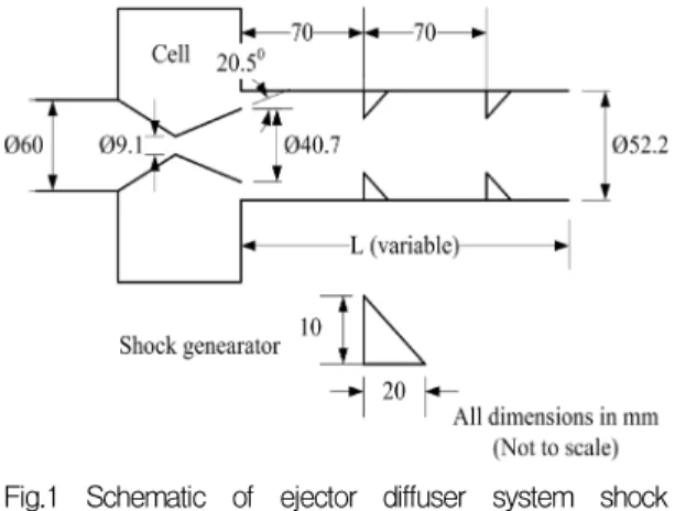
Fig. 1 shows the experimental setup [6].
High- pressure nitrogen gas is supplied to a conical nozzle having an exit half angle of 20.50. The annular space surrounding the nozzle is served as the test cell. The SED is exhausted to the atmosphere. Shock generators were arranged inside the SED as shown.
Fig.1 Schematic of ejector‐diffuser system shock generators (Ref. 6).
2. Numerical Scheme
Schematic of the vacuum ejector system with the computational boundary conditions are shown in Fig. 2. Simulations were done with a single conical nozzle of exit diameter 40.7 mm, diffuser duct of L/D = 3.72. Shock generators are placed at distance of 70mm from each other. Far space has been extended 15D and 6D in the linear and lateral directions.
Fig. 2 Schematic of ejector‐diffuser with boundary conditions.
Steady, two‐dimensional Reynolds-averaged compressible Navier‐Stokes equations are solved with SST-k- turbulence model for closure. The perfect gas relation and a
constant ratio of specific heats are used in the computation. The numerical boundary conditions used are total pressure and temperature (300 K) at the inlet, static pressure outlet, and the axis boundary conditions.
Nitrogen gas with ideal gas approximation is used as working fluid and viscosity is calculated by Sutherland law. All the walls are considered adiabatic with no slip. For all equations, convective terms are discretized using a second‐order upwind scheme:
inviscid fluxes are derived using second order flux splitting. Diffusion terms are always cast into a central difference form. The resulting system is time‐preconditioned, in order to overcome the numerical stiffness encountered at low Mach number. The discretized system is solved in a coupled way, using block Gauss Seidel algorithm.
3. Results and Discussion
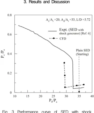
Fig. 3 Performance curve of SED with shock generators.
The conical rocket nozzle with exit half
angle of 20.50 is simulated with a short SED having L/D of 3.72. Cold N2 gas was supplied from high pressure cylinders, with P0
ranging from 0.1 to 4.0 MPa. A small cavity around the nozzle served as the vacuum test chamber. The ratio of distance between shock generators and SED diameter is 1.34. Some of the typical results are being presented here.
A typical characteristic curve of plain SED and SED with shock generators is shown in Fig. 3.
The hysteresis occurring in short diffusers is currently not evaluated. It can be clearly seen that with shock generators the starting pressure ratio of the SED is reduced, when compared to the plain SED. Qualitative trends are predicted by the CFD also. Hence, this device can be highly useful in the power savings of the HAT facility.
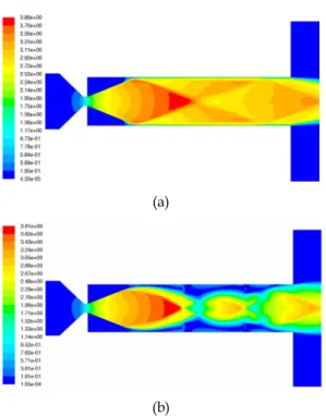
Shown for comparison are the Mach number distributions with and without shock generators. Ejectors with second throat are superior to those with straight diffuser, in the sense that they require a fewer overall starting pressure ratio. The shock generators act like a second throat (region between shock generators, cf. Fig. 4b), which explains the observed reduction in the starting pressure ratio.
The formation of second throat can be clearly be seen (with shock generators) in Fig. 5. The axial location of shock generators can influence the expansion from the nozzle, as the nozzle flow is not expanded fully (cf. Fig. 5b) due to the interaction of the primary jet and the shock generator. Placing shock generators even closer to the nozzle can result in nozzle un‐starting.
The position as well as the size/geometry of the shock generators can have a dominant influence on the characteristics of the SED. However, the present study is limited to the performance analysis of SED with 10mm shock generators placed at an equal interval of 70 mm.
(a)
(b)
Fig. 4 Contours of Mach number for (a) plain SED and (b) SED with shock generators.
(a)
(b)
Fig. 5 Sonic‐lines for (a) plain SED (b) SED with shock generators.
4. CONCLUSION
In the present work, a large number of CFD simulations have been carried out to investigate in detail, a method by which the performance of a vertical rocket engine test stand can be increased. Results clearly showed that this device is highly useful in the vertical firing of rocket engine test stands. The improvement comes from a reduction of the SED length as well as the starting pressure ratio. The pressure recovery characteristics of the SED are increased with shock generators, which can result in substantial savings in power requirements. In addition, no major design changes are not required in the existing HAT facility to accommodate the shock generators. The cooling of shock generators exposed to the hot rocket engine exhaust is not a problem of great significance as it can be tackled by the conventional cooling methods. Hence, the addition of shock generators can result in substantial improvement of short ejector‐diffuser systems.
REFERENCE
1 V. Lijo, H.D. Kim, T. Setoguchi, S. Matsuo, Numerical simulation of transient flows in a rocket propulsion nozzle, International Journal of Heat and Fluid Flow 31, pp.409~417, 2010.
2. E.P. Neumann, F. Lustwerk, Supersonic diffuser for wind tunnels, Journal of Applied Mechanics 16, pp.195~202, 1949.
3. B.H. Gothert, High altitude and space simulation testing, ARS Journal 32, pp.872~882, 1962.
4. R.C. German, R.C. Bauer, J.H. Panesci, Methods for determing the performance of
ejector‐diffuser systems, Journal of Spacecraft and Rockets 3, pp.193~200, 1966.
5. E.J. Roschke, P.F. Massier, H.L. Gier, Experimental investigation of exhaust diffusers for rocket engines, Technical Report No.32‐210, Jet Propulsion Laboratory, California Institute of
Technology, California, United States, 1962.
6. K. Annamalai, T.N.V. Satyanarayana, V.
Sriramulu, K.A. Bhaskaran, Development of design methods for short cylindrical supersonic exhaust diffuser. Experiments in Fluids 29, pp.305~308, 2000.