A Study on the Gas-Liquid Mixing Characteristics in Reactor System Using Ejector
ZhenHua Jin
†, Tony Utomo
*, HanShik Chung
**, HyoMin Jeong
**, YouSik Shin
***and SangChul Lee
***Key Words : mixing system, gas-liquid ejector, loop reactor, mass transfer, CFD Abstract
The aim of this paper is further studies to achieve deeper understanding in this field. First investigate the influence of operating conditions and design parameters on the hydrodynamics and the mass transfer properties of a loop reactor. This paper provides a literature review on the ejectors applications in the mixing system. A number of studies are grouped and discussed in several topics such as the background, theory of ejector, mixing characteristics, optimization of the system. Since the high efficiencies reactor using ejector widely used in gas-liquid system, especially in a number of chemical and biochemical processes. This is due to their high efficiency in gas dispersion resulting in high mass transfer rate and low power requirements.
Thus ejector has been applied to the mixing system. An investigation on hydrodynamics and mass transfer characteristics of gas-liquid ejector has been carried out using three-dimensional CFD modeling.
1. Introduction
In chemical process industry, efficient gas-liquid contacting is essential in processes such as hydrogen- nation, chlorination, etc. Due to their favorable mass transfer and mixing characteristics, ejectors are being increasingly used in the chemical and biochemical industries. [1, 2]
Many multiphase contacting devices have been described. They can be roughly classified into three groups:
▪ mechanically stirred tanks or columns in which a gas phase is dispersed using the mechanical power supplied by one or several impellers;
▪ gas-driven reactors in which power is mainly supplied by the gas phase; these include first pneumatically- agitated reactors, such as bubble columns and airlift reactor in which the liquid is the continuous phase and
for which power supply derives from gas compression, expansion; they include also packed columns in which the gas constitutes the continuous phase and for which power supply derives from the kinetic energy of the gas;
▪ liquid-driven reactors in which the mechanical power for dispersion is obtained from the kinetic energy of the liquid phase. [3]
Loop reactors represent a very attractive alternative technology for gas-liquid system. A typical loop reactor consists of a vessel, an ejector and a circulation loop equipped with a pump. The benefit of the loop reactor is efficient gas-liquid mass transfer which is accomplished with the ejector. Typically no mechanical agitation is needed.
In order to achieve the best performance of the reactor system, mathematical modeling is necessary. An appropriate model for the loop reactor should be fulfils at least the following requirements: the reaction kinetics should be described in a realistic, the non-idealities of the flow pattern should be included and the dynamic characteristics of the reactor should be a vital part of the model. [4]
Jet loop reactor with two phase flow has found various applications within areas such as fermentation and wastewater treatment or chemical reaction.
2. Background and theory
2.1 Ejector theory
The reactor in design and requires no extra compression device for dispersion of the gas dispersion as the gas
†Graduate School, Department of Mechanical and Precision Engineering, Gyeongsang National Univ.
E-mail : [email protected] TEL : (055)646-4766 FAX : (055)644-4766
*
Graduate School, Department of Mechanical and Precision Engineering, Gyeongsang National Univ.**
School of Mechanical and Aerospace Engineering, Gyeongsang National Univ. Institute of Marine Industry.***
Department of Mechatronics, Koje Univ.phase is sucked in and dispersed by the high-velocity liquid jet discharging through the ejector. The beneficial use of an ejector as a gas distributor in aerated towers has been highlighted the literature. The ejector provides high shear between the phases creating a fine gas-liquid dispersion, thereby giving smaller bubbles. In the gas- liquid reactor the main part is ejector. A standard ejector consists of a nozzle, throat, gas suction chamber, mixing tube and diffuser. Liquid is supplied to the ejector via nozzle and the fast liquid jet produced by the nozzle entrains and disperses the gas.
2.2 Mixing shock
According toWitte(1969), a so-called mixing shock occurs in the mixing tube. In the region of this region of this mixing shock, the two-phase flow changes from jet flow into a homogeneous bubble flow and this flow pattern transition is accompanied by a sudden pressure build up. Behind this mixing zone both phases flow homogeneously through the remaining part of the ejector.
When the gas-liquid flow stream leaves the ejector, a secondary dispersion of bubbles is obtained in the bulk fluid of the reactor vessel. According to Cunningham and Dopkin (1974), the location of the mixing shock zone is of key importance for the ejector performance. The optimum dispersion efficiency is achieved when the liquid jet breaks up just at the end of the mixing tube. If the jet disintegration occurs earlier, the flow of the homogeneous gas-liquid mixture through the remaining part of the mixing tube results in excessive friction losses.
If on the other hand, the mixing tube is too short, the jet does not break up and accordingly the momentum transport between the phases does not occur. As a result, the ejector efficiency in such a case strongly decreases.
The occurrence of the jet break up and the position of the mixing shock zone in the mixing tube depend generally on the gas and liquid flow rates, on the ejector pressure drop and on its geometrical parameters (nozzle, diameter and length of the mixing tube, angle of diffuser). For given flow conditions, ejector design has to be optimized to provide maximum dispersion efficiency. Due to the sensitivity of the location of the mixing shock region to the flow conditions, the dispersion efficiency decrease significantly with the variations of the liquid flow rate.
Numerous attempts have been reported in the literature at facilitating the jet disintegration and stabilizing the position of the mixing shock zone within a wide range of flow conditions, with the ultimate purpose of making the dispersion efficiency of ejectors less dependent on their working conditions. [5, 6]
3. Application of gas-liquid ejector in reactor system
3.1 Principle of gas-liquid ejector operation
Fig.1 shows the operating principles of gas-liquid ejector. The pumped liquid through the nozzle that provides a high velocity jet of fluid to create a low- pressure region in the suction chamber.
Fig. 1 Gas-liquid ejector
The secondary or entrained fluid typically is a gas phase, gets sucked into this chamber. The gas and liquid phases get mixed and gas-liquid dispersion is created in the mixing shock, result into much smaller bubbles. Thus, ejector gives better gas-liquid mass transfer rates and also subsequently higher rates of reaction.
3.2 Modeling of the reactor system
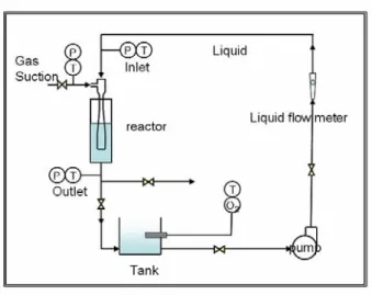
A schematic diagram of the ejector and the experimental facility used is show in Fig.2. As the working fluids used in this research were water as motive fluid and air as secondary fluid, the assumption of incompressible flow was seems to be appropriate. The experiments were carried out in an acrylic column of 0.2m in diameter and 0.475 m in height. The volumetric gas-liquid mass transfer rates were calculated from the oxygen concentration in the liquid phase. Make following assumption. The gas flow is considered to be constant and a pure gas is supplied.
This paper conducted to investigate performance and mass transfer in the mixing system. Also investigate on the hydrodynamics and mass transfer characteristics of gas-liquid ejector using CFD analysis. In order to approach optimize the geometry of gas-liquid ejector and other operating condition.
Fig.3 Schematic diagram of gas-liquid
4. Experimental results
Fig.3 shows the vacuum pressure for different diffuser angle. When diffuser angle is 5.0 the vacuum pressure is higher and when the flow rate of liquid is low, the vacuum difference is big but the vacuum difference was narrow with the flow rate increases.
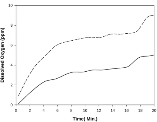
Fig.4, Fig.5 shows the effect of flow rate and diffuser angle on the two phases mixing. The dissolved oxygen is increase with increasing of flow rate at the both case. At the some flow rate of liquid, the dissolved oxygen is higher when diffuser angle is 5.0 but the difference is decreasing.
Flow rate (LPM)
65 70 75 80 85 90 95
Vaccum Pressure (mmHg)
500 550 600 650 700 750
Diffuser angle is 3.5 degree Diffuser angle is 5.0 degree
Fig.3 Distribution of vacuum pressure for different diffuser angle
Time(Min)
0 2 4 6 8 10 12 14 16 18 20
Dissolved Oxygen(ppm)
0 2 4 6 8 10
QL=70 LPM QL=80 LPM QL=90 LPM
Fig.4 Variation of dissolved oxygen for θ=3.5°
Time( Min.)
0 2 4 6 8 10 12 14 16 18 20
Dissolved Oxygen (ppm)
0 2 4 6 8 10
QL=70 LPM QL=80 LPM QL=90 LPM
Fig. 5 Variation of dissolved oxygen for θ=5.0°
Time( Min.)
0 2 4 6 8 10 12 14 16 18 20
Dissolved Oxygen (ppm)
0 2 4 6 8 10
3.5 deg 5.0 deg
Fig. 6 Distribution of dissolved oxygen (QL=80LPM)
Time( Min.)
0 2 4 6 8 10 12 14 16 18 20
Dissolved Oxygen (ppm)
0 2 4 6 8 10
Fig. 7 Distribution of dissolved oxygen (QL=80LPM)
Time( Min.)
0 2 4 6 8 10 12 14 16 18 20
Dissolved Oxygen (ppm)
0 2 4 6 8 10
Fig. 8 Distribution of dissolved oxygen (QL=90LPM)
5. Numerical analysis
Recently, with the rapid development of numerical solution method, some researchers attempted to apply Computational Fluid Dynamics (CFD) in modeling the flow within ejectors. The merits of using CFD approach is the capability on producing details the flow field and at any given operating conditions or model geometry can be simulated for extensive analysis of the flow related properties. Data that is difficult to obtain in an experimental set up can be easily analyzed using CFD.
5.1 model and boundary conditions
Fig.9 shows the basic shape of ejector used in CFD analysis. The grid generate shown in Fig.10. The governing equations are solved using the commercial
Fig. 9 Ejector model
The terms of computation were steady state and incompressible flow. Turbulent model was use standard
ε
−
k high Reynolds number model. Use SIMPLE algorithm and upwind scheme. Maximum residual tolerance was set under 0.0005.
The ejector configuration used in the present study had a mixing tube diameter of 22 mm and diffuser outlet diameter of 40 mm (i.e. diffuser angle of 3.5 and 5.0).
The nozzle diameter used was 8.5 mm. The mixing tube lengths were varied 70 LPM, 80 LPM, 90 LPM, respectively.
Fig. 10 The ejector grid generation
5.2 Results and discussion
0.00 0.05 0.10 0.15 0.20 0.25 0.30 0.35 0.40 0.45 0.50
Pressure (Pa)
0 1e+5 2e+5 3e+5 4e+5 5e+5
QL= 70 LPM QL= 80 LPM QL= 90 LPM
Distance along the ejctor (m)
0.00 0.05 0.10 0.15 0.20 0.25 0.30 0.35 0.40 0.45 0.50
Pressure (Pa)
0 1e+5 2e+5 3e+5 4e+5 5e+5
QL= 70 LPM QL= 80 LPM QL= 90 LPM
Fig. 12 Pressure distribution along the ejector for various QL (θ=5.0°)
Fig. 13 Contour of pressure along the ejector (θ=3.5°, QL =90 LPM)
Fig. 14 Contour of pressure along the ejector (θ=5.0°, QL =90 LPM)
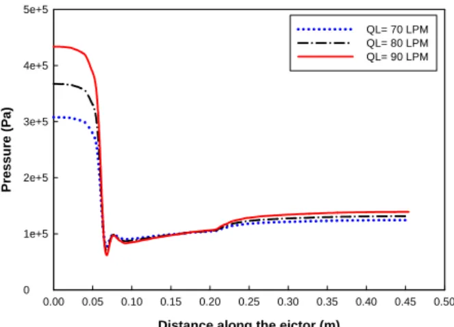
Fig.11 and Fig.12 shows the pressure along the ejector centerline for various flow rates. For pressure boundary conditions apply to experimental pressure value. With an increase in the flow rate the two phase pressure drop decreases. It was obviously at the nozzle can get lower pressure with the flow rate was higher
Fig.13 and Fig.14 shows the contour pressure along the ejector by numerical process. Fig.15 shows the comparison between two ejector models when flow rate was 90LPM. Fig.16 and Fig.17 shows the air fraction along the ejector when the high kinetic energy produces local low pressure zones resulting in entrain and disperse gas phase. Red color means air and blue means water.
Two phase flow through the nozzle, mixing tube and
Distance along the ejctor (m)
0.00 0.05 0.10 0.15 0.20 0.25 0.30 0.35 0.40 0.45 0.50
Pressure (Pa)
0 1e+5 2e+5 3e+5 4e+5 5e+5
3.5 degree 5.0 degree
Fig.15 Pressure distribution along the ejector for different θ
Fig. 16 Air fraction along the ejector (θ=3.5°, QL =90 LPM)
Fig. 17 Air fraction along the ejector (θ=5.0°, QL =90 LPM)
6. Conclusions
This paper describes a basic background and development of a gas-liquid ejector and its application in the reactor system. At this moment, it can be said that the understanding in gas-liquid reactor system theory has not been completely cleared. Now many researchers try to make new assumptions on mixing and flowing characteristic and applied on the computer simulation analysis. Also try to compare with experimental results then investigate the mass transfer properties, flow characteristics and characteristics of the reactor so that
Increasing attention is being paid to research and practice of high efficiency reactor system using gas- liquid ejector. Gas-liquid ejector is the critical component of reactor system. The system efficiency is not only depends on the system operating conditions, but also the ejector configuration has a significant effect.
From experiment and numerical analysis results can be summarized as follows:
(1) When diffuser angle is 5.0 the vacuum pressure is higher than diffuser angle is 3.5 and when the flow rate of liquid is low, the vacuum difference is big but the vacuum difference was narrow with the flow rate increases.
(2) The dissolved oxygen is increases by increasing of flow rate at the both case.
(3) At the some flow rate of liquid, the dissolved oxygen is higher when diffuser angle is 5.0 but the difference is decreasing.
(4) With an increase in the flow rate at the nozzle can get lower pressure.
(5) In the diffuser angle is 3.5 case can reach the homogeneous pattern earlier
The major purpose of using gas-liquid ejector is to increase mass transfer and efficiency. It is most desirable to design a device or select an operating condition. For this object more of knowledge and reasonable estimates are needed.
Acknowledgements
The authors gratefully acknowledge support provided by the second-phase of BK21 project, Industry-University- Institute R&D consortium and Korea Heat & Fluid Technology.
References
(1) Kandakure, M. T., Gaikar,V.G., Patwardhan, A.W., 2005, "Hydrodynamic aspects of ejectors", Chemical Engineering Science, 60(2005) 6391~6402.
(2) Lee, J., 2004, "Gas-Liquid mass transfer of VOC in the jet loop reactor with circulation of surfactant solution", thesis pp.4~11.
(3) Gouirich, B., Azher, N. E., Vial, C., Soulami, M. B., Ziyad, M., Zoulalian, A., 2006, "Influence of operating conditions and design parameters on hydrodynamics and mass transfer in an emulsion loop venturi reactor", Chemical Engineering and Processing.
(4) Lehtonen, J., Kaplin, J., Salmi, T., Haario, H., Vuori, A. and Tirronen, E, 1999, "Modelling and scale-up of a loop reactor for hydrogenation processes", Chemical Engineering Science, 54(1999) 2793~2798.
(5) Havelka, P., Linek, Sinkule, V., Zahradnik J. J. and Fialova, M., 1997, "Effect of the ejector configuration on the gas suction rate and gas hold-up in ejector loop reactors", Chemical Engineering Science. Vol, 52, No.
11, pp.1701~1713.
(6) CramersP.H.M.R. and A. A. C. M. Beenackers , 2001,
"Influence of the ejector configuration, scale and the gas density on the mass transfer characteristics of gas- liquid ejectors", Chemical Engineering Journal 82(2001)131~141.