Ultrasonic Estimation and FE Analysis of Elastic Modulus of Kelvin Foam
Nohyu Kim*✝ and Seungyong Yang*
Abstract The elastic modulus of a 3D-printed Kelvin foam plate is investigated by measuring the acoustic wave velocity of 1 MHz ultrasound. An isotropic tetrakaidecahedron foam with 3 mm unit cell is designed and printed layer upon layer to fabricate a Kelvin foam plate of 14 mm thickness with a 3D CAD/printer using ABS plastic.
The Kelvin foam plate is completely filled with paraffin wax for impedance matching, so that the acoustic wave may propagate through the porous foam plate. The acoustic wave velocity of the foam plate is measured using the time-of-flight (TOF) method and is used to calculate the elastic modulus of the Kelvin foam plate based on acousto-elasticity. Finite element method (FEM) and micromechanics is applied to the Kelvin foam plate to calculate the theoretical elastic modulus using a non-isotropic tetrakaidecahedron model. The predicted elastic modulus of the Kelvin foam plate from FEM and micromechanics model is similar, which is only 3-4% of the bulk material. The experimental value of the elastic modulus from the ultrasonic method is approximately twice as that of the numerical and theoretical methods because of the flexural deformation of the cell edges neglected in the ultrasonic method.
Keywords: Ultrasonic Nondestructive Evaluation, Kelvin Foam, Elastic Modulus, Acoustic Wave Velocity, Cellular Material, Porosity
[Received: November 23, 2015, Revised: December 20, 2015, Accepted: December 29, 2015] *School of Mechatronics Engineering, Korea University of Technology and Education, Cheonan-si, Chungcheongnam-do 31253, Korea ✝Corresponding Author: [email protected]
ⓒ 2016, Korean Society for Nondestructive Testing
1. Introduction
Three-dimensional cellular materials are widely used in the energy and transport industries as lightweight structural materials to achieve substantial gains in terms of increasing heat transfer, mixtures and chemical reactions. These materials can provide simultaneously a set of excellent qualities e.g. mechanical, thermal, catalytic that lead to significant reductions in cost, weight and offer opportunities for applications in diverse areas including auto- mobiles, fuel cells, chemical engineering.
This cellular material is primarily used for its mechanical properties especially in the aerospace and transportation where lightweight and resistant structures are needed. The thermal properties of such materials are equally important in many targeted applications e.g. cooling of
electronic components, thermal insulation (sandwich panels). Heat exchangers, reactors with foam as internals are one of the good examples of application. The acoustic properties are also used in applications such as vibration damping, adjusting the sound and noise reduction [1]. Their field of applications have increased substantially in recent years due to the properties already mentioned. For example, porous foams attract an interest as biomaterials for implantation purpose as the introduction of pores into the bulk material provides in-growth of living tissues and firm fixation in addition to reducing the alloy density [2,3]. It is a good candidate as a biomedical apparatus and implant device. Metallic foam structure has low enough value of elastic modulus which is much smaller than that of the bulk metal and comparable to that of human bone. Kim et al [4] produced
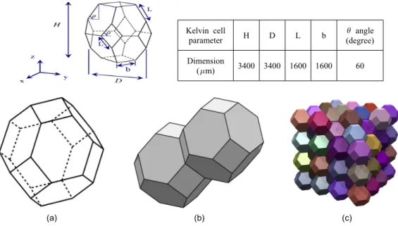
Table 1 Dimensions of Kelvin cell edges
Kelvin cell
parameter H D L b angle
(degree) Dimension
(m) 3400 3400 1600 1600 60
(a) (b) (c)
Fig. 1 Kelvin structure, (a) unit cell, (b) 1-D, and (c) 3-D formation
the Kelvin foam or tetrakaidecahedron is manufactured by 3D printer with ABS plastic material to investigte the Young’s modulus of the foam structure by ultrasonic method. It is shown from experiment that the Young’s modulus of the produced Kelvin foam is about 4% of the bulk value of the ABS plastic material, which agrees with theoretical results from FEM analysis and micromechanics model.
2. Fabrication of Kelvin Foam Plate
The geometrical problem of partitioning three-space into regions of identical volume with the least total interfacial area is known as the
intersection of multiple faces. It has a 14-sided polyhedron possessing eight hexagonal and six quadrilateral sides and packs to fill space. These cells are repeated periodically in the space so they can completely fill it like Fig. 1(c).
The unit cell structure is usually described by its morphological parameters, namely cell size, pore size, strut thickness and porosity. The Kelvin cell considered in this study is described in Fig. 2, and Table 1. CAD image of the Kelvin cell is illustrated in Fig. 2(a) with a sample Kelvin foam structure made by 3D printer in Fig. 2(b) which consists of two layers of 16 open cells with 81% of porosity.
(a) (b)
Fig. 2 CAD image of the unit cell and a 3D-printed example of Kelvin structure
(a) (b)
Fig. 3 Kelvin foam plate fabricated by 3D printer, (a) Kelvin foam itself, (b) two phase mixture of Kelvin foam and paraffin wax
For ultrasonic measurement, four layers of the Kelvin cells are printed layer upon layer by 3D printer to produce a 14 mm-thick foam plate (50mm wide and 100mm long) as shown in Fig.
3(a). As shown in Fig. 2(b) and Fig. 3, the Kelvin foam plate designed in this study has so many empty space (81 % of porosity), that the ultrasound cannot penetrate at all.
Therefore, it is filled with paraffin wax to make a mixture of Kelvin structure with paraffin wax as in Fig. 3(b). The paraffin wax in the mixture works as a filler to print and support the Kelvin foam, but also to match the acoustic impedance between the Kelvin foam and empty pores. Fig. 3(a) represents the Kelvin cell structure itself, and Fig. 3(b) shows the two phase mixture, a Kelvin foam infiltrated with the paraffin wax.
3. Ultrasonic Measurement of Elastic Modulus of Kelvin Foam Plate
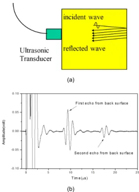
Measurements of ultrasonic velocities are conducted to estimate the elastic modulus of 3D-printed Kelvin structure. In the present work, the ultrasonic velocity measurements were carried out by using pulse-echo method, which uses the time-of-flight(TOF) measurement to calculate the wave velocity. In the TOF method, acoustic transducer generates a pulse signal that propagates through the structure and is reflected back, being detected after a delay. The duration of the wave propagation from the front surface to the back surface of the Kelvin structure depends on the thickness of the structure as well as on the elastic properties of the traveling medium (Kelvin structure). For an isotropic
(b)
Fig. 4 Wave propagation and reflection in Kelvin foam plate
inside the Kelvin foam plate. At the start of a measurement, a pulse generator excites a voltage pulse in a pulser/receiver (Panametrics 5072PR), which is converted in the ultrasonic transducer (Panametrics V103-RB) to an ultrasonic pulse of 1MHz center frequncy which propagates through the plate at a velocity c. When it propagates, the pulse reflects first at the interface of the transducer and the Kelvin plate, next at the back surface, and returns to the transducer repeating this round-trip travel as shown in Fig. 4(b).
After the back-wall echoes are recorded in digital oscilloscope (Lecroy Wave Runner 530), the time interval between two maximum peaks of consecutive echoes is measured. Fig. 4(b) shows one example of the measurement of the TOF for the Kelvin foam plate, where multiple echo signals from the back surface is captured and used to calculate the TOF of the ultrasonic wave. The acoustic velocity, , is expressed through the TOF and the thickness of the plate,
, by the simple relation of Eq. (2)
TOF (2)
The TOF method is very easy and simple to realize on actual sensor unless it suffers from low signal-to-noise ratio (SNR) or signal shape distortion. In this work, it works well due to high SNR without considerable signal distortion.
If the Kelvin foam plate produced in Fig.
2(b) is assumed as a composite material, according to the elastic theory of composite materials, the elastic modulus of the two phase
mixture, denoted by E, may be given by using the rule of mixtures[7]
, (3)
where, is the elastic constant for paraffin wax, is the elastic constant for Kelvin foam,
and are the volume fraction of wax and Kelvin foam. Since the bulk material of Kelvin foam (ABS plastic) has a broad range of elastic property, its elastic modulus is determined experimentally by the same ultrasonic TOF method using a coin-type specimen of 100%
bulk ABS plastic as shown in Fig. 5(a). The paraffin wax is also tested in the same way for accurate estimation of the elastic modulus of Kelvin foam. Fig. 5(b) displays the acoustic waveforms of 1 MHz ultrasound acquired from the test specimens, which include two coin specimens of Fig. 5(a) and the mixture of Kelvin foam and wax in Fig. 3(b). Fig. 5(b) shows that the mixture has a wave speed
(a) (b) Fig. 5 Shapes and waveforms of bulk ABS plastic and paraffin wax
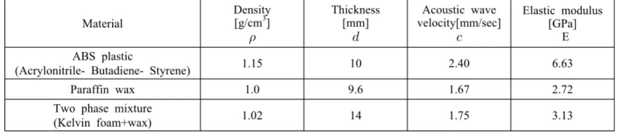
Table 2 Material property of ABS plastic, paraffin wax and the mixture
Material
Density [g/cm3]
Thickness [mm]
Acoustic wave velocity[mm/sec]
Elastic modulus [GPa]
E ABS plastic
(Acrylonitrile- Butadiene- Styrene) 1.15 10 2.40 6.63
Paraffin wax 1.0 9.6 1.67 2.72
Two phase mixture
(Kelvin foam+wax) 1.02 14 1.75 3.13
Table 3 Elastic modulus of two phase mixture of Kelvin foam and wax
Method Elastic modulus of two phase mixture
[GPa]
Ultrasonic test 3.13
The rule of mixture 3.46
Fig. 6 One-dimensional spring model of two phase mixture of Kelvin structure and wax
between the bulk ABS plastic and the paraffin wax, but much closer to the wax’s wave velocity. From the acoustic wave velocity obtained from Eq. (2) in ultrasonic test, the elastic modulus of the mixture is determined by Eq. (1) first. Table 2 lists the elastic and acoustic property of ABS plastic, paraffin wax, and the two phase mixture of Kelvin foam and wax. The elastic modulus of two phase mixture is compared in Table 3 with theoretical elastic modulus based on the rule of mixture derived from the mechanics of composite in Eq.(3). It shows a good agreement between the estimate of ultrasonic test and composite model for the mixture of the Kelvin foam and wax.
Next, in order to extract the elastic modulus of the Kelvin foam from the elastic modulus of the mixture, a simple hypothesis is formed that the Kelvin structure and the wax work as two elastic springs connected in parallel as represented in Fig. 6. In Fig. 6, is the elastic modulus (spring constant) of the Kelvin foam and is
the elastic modulus (spring constant) of the paraffin wax. On this assumption, the resultant elastic modulus (spring constant), of the mixture is equal to the simple sum of two elastic spring constants, i.e., . Since
listed in Table 4.
4. FEM Modeling and Microstructural Analysis of Kelvin Foam
In the micromechanics theory, an isotropic tetrakaidecahedron is adopted to develop equations for the Young's modulus for isotropic, open- celled Kelvin foams [8]. They assumed that the mechanical behavior of open-celled foams could be simulated by treating the cell edges as structural elements possessing axial, bending, and torsional rigidity. The equations for the foam elastic constants were derived and written in terms of the cell edge length L, the edge cross-sectional area A, moment of inertia I, and torsional constant J, as well as the Young's modulus E, and shear modulus G of the solid material. Recently, to treat non-isotropic Kelvin foams, Sullivan [9,10] has developed equations for the elastic constants and tensile strengths for non-isotropic, open-celled foams using the most general description of the Kelvin unit cell geometry as shown in Fig. 2(a). The tetrakaidecahedron with eight hexagonal sides, two horizontal square sides, and four rhombic- shaped vertical sides is uniquely defined by specifying the value of any three of the unit cell dimensions , , , , and . The same cell structure is also considered in this work for FEM analysis and theoretical calculation of elastic modulus. In Fig. 2(a), the angle defines the orientation of the hexagonal faces with respect to the direction z, as well as the obtuse
strength equations were obtained based on the critical (Euler) buckling load of the edges including the effects of shear deformation. In this paper, FEM analysis is performed on the same tetrakaidecahedron model of Sullivan to estimate the elastic modulus of the Kelvin foam described in Table 1 under the assumption that the majority of the solid mass is concentrated in the cell edges and that the faces do not contribute significantly to the overall mechanical behavior of the Kelvin foam. FEM result is also compared with the theoretical estimate of the elastic constant based on the equations from Sullivan’s model [10]. From Sullivan’s work, the equation for the elastic constant can be written as Eq. (4).
24 sin( )
2[cos ( ) (12 /2 2)sin ( )]( 2 cos( )2 )2 θ
θ θ θ
= + +
B K
E E I
L I AL L b
(4) where, is the elastic constant for bulk material (ABS plastic) of the Kelvin foam, is the elastic constant for Kelvin foam structure, A is the edge cross-sectional area of cell strut, and I for the area moment of inertia of the cell strut.
The mechanical behavior of Kelvin foam depends on the properties of the cell wall material, and the cell geometry. The individual response of cells to a loading is also strongly influenced by their location in the material, for instance, deformation of cells located in the bulk, surrounded by other cells is more
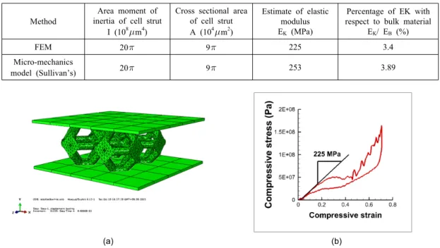
Table 5 Simulation results of FEM and micromechanics model
Method
Area moment of inertia of cell strut
I (108m4)
Cross sectional area of cell strut A (104m2)
Estimate of elastic modulus EK (MPa)
Percentage of EK with respect to bulk material
EK/ EB (%)
FEM 20 9 225 3.4
Micro-mechanics
model (Sullivan’s) 20 9 253 3.89
(a) (b)
Fig. 7 FEM model and compressive stress-strain behavior of Kelvin foam
constrained comparing to cells located adjacent to stress-free boundaries. It is reported that if the length, width, and thickness of a foam sample are large enough to include many cells, the differences in cellular response to a macroscopic loading are averaged out, leading to size-independent effective properties, as is the case in many practical applications including this study [11]. In this study, only a set of four cells is taken into account for FEM modeling, which is represented in Fig. 7(a), since the Kelvin foam has a symmetry in the direction of thickness (z-direction) and length (x and y- direction). Four unit cells are joined together on rhombic-shaped vertical sides and compressed by two artificial rigid plates on the top and the bottom of the cells as described in Fig. 7(a).
The cell material has the same Young’s modulus of 6.60 Gpa as the ABS plastic obtaind from experimental result in Table 2. As in experiment, the volume fraction of the Kelvin unit cell is 19% and the remaining 81% of the material is empty. Compressive displacement boundary motion is applied on the top of the body and
the reaction force is computed at the bottom of the body using SolisWorks. Average strain and stress are computed by dividing the values by the height and the surface area. Fig. 7(b) shows a progressive elastic behaviour of the Kelvin structure as the compressional load is increasing, where multiple buckling can be seen during the loading process. The average Young’s modulus of the structure is calculated about 225 Mpa, which is 3.4% of the stiffness of the bulk material, 6.6 Gpa. In Table 5, FEM result appears to be comparable to the analytical value of elastic modulus of the micromechanics model given by Eq. (4).
5. Discussion
In this paper, the elastic modulus of Kelvin foam plate was investigated by ultrasonic method and FEM analysis. From the direct comparison of the elastic modulus values by two methods, a noticeable difference is observed, 410 MPa from ultrasonic test and 225 MPa from FEM. Microscopic analysis
microstructural model. In fact, it is well known from previous reports that the flexural deformation of cell edges play an important role in the total deformation of the Kelvin foam structure. Since bulk waves like longitudinal or shear wave, which is used in this work, cannot excite flexural deformation of cell edges, it is necessary to suppress the flexural mode for more accurate ultrasonic estimate by means of decreasing either the cell size of Kelvin foam or the ultrasonic frequency. As the acoustic frequency becomes smaller down to 100 kHz, the effect of flexural deformation is expected to be smaller and negligible comparing with compressional deformation. In the future study, a low frequency of ultrasound such as 100 kHz should be employed to estimate the Young’s modulus. Nevertheless, the ultrasonic method developed in this work provides an excellent nondestructive tool not only to estimate the elastic modulus for Kelvin foam in macroscopic sense, but also to assess the porosity and density change of Kelvin foam structure whose porosity is not priori-known as in the medical case of osteoporosis diagnosis, implant dentistry and evaluation of bone density of whole body.
6. Conclusions
The elastic modulus of a 3D-printed Kelvin foam plate with 81% porosity is evaluated by the ultrasonic method using acoustic wave velocity based on TOF measurement. The
analysis for the tetrakaidecahedron model are also conducted to calculate the elastic modulus, which is about the same and only 3-4% of the bulk material. It is found that ultrasonic estimate of the elastic modulus of the Kelvin foam is as twice as the numerical and theoretical results because of the flexural deformation of cell edges neglected in the ultrasonic method.
It can be concluded from FEM and experiments results that the ultrasonic method is useful and effective to evaluate the elastic modulus of Kelvin foam structures in a fast and simple way. It is also expected that it has great potential for medical applications such as the measurement of bone density as well as industrial applications like industrial foams used for shock absorption and insulation.
Acknowledgment
This work was supported by Radiation Technology R&D program through NSF funded by the Ministry of Science, ICT & Future Planning (NRF-2013M2A2A9043274) and partly by University Research Fund of Korea University of Technology and Education.
References
[1] P. Kumar, "Investigation of Kelvin-like solid foams for potential engineering applications:
An attractive set of geometrical and thermo-hydraulic properties," Ph. D thesis,
Department of Mechanical Engineering, Aix-Marseille University, France (2014)
[2] R. A. Ayers, S. J. Simske, T. A. Bateman, A. Petkus, R. L. C. Sachdeva and V. E.
Gyunter, "Effect of nitinol implant porosity on cranial bone ingrowth and apposition after 6 weeks," Journal of Biomedical Materials Research, Vol. 45, No. 1, pp.
42-47 (1999)
[3] G. Ryon, A. Pandit and D. P. Apatsidis,
"Fabrication methods of porous metals for use in orthopaedic applications," Biomaterials, Vol. 27, No. 13, pp. 2651-2670 (2006) [4] Y-W Kim, T-H Nam and S. Young,
"Production of a highly porous Ti-Ni shape memory alloy by solid state sintering of rapidly solidified fibers," Science of Advanced Materials, Vol. 6, pp. 2005-2009 (2014) [5] C. Prest, J. Poole, J. Stevick, T. Waniuk
and Q Pham, "Layer-by-layer construction with bulk metallic glasses", United States Patent Application Publication, No.
US20130309121 (2013)
[6] C. Tekoglu, L. J. Gibson, T. Pardoen and P. R. Onck, "Size effects in foams: Experi-
ments and modeling," Progress in Materials Science, Vol. 56, pp. 109-138 (2011) [7] C. C. Chamis, "Mechanics of composite
materials: Past, present and future," Journal of Composites Technology and Research, Vol. 11, No. 1, pp. 3-14 (1989)
[8] W. E. Warren and A. M. Kraynik, "Linear elastic behavior of a low-density Kelvin foam with open cells," Journal of Applied Mechanics, Vol. 64, pp. 787-794 (1997) [9] R. M. Sullivan, L. J. Ghosn and B. A.
Lerch, "Application of an elongated Kelvin model to space shuttle foams," Journal of Spacecraft and Rockets, Vol. 46, No. 2, pp. 411-418 (2009)
[10] R. M. Sullivan, L. J. Ghosn and B. A.
Lerch, "A general tetrakaidecahedron model for open-celled foams," International Journal of Solids and Structures, Vol. 45, pp. 1754- 1765 (2011)
[11] R. Gabbrielli, "Foam geometry and structural design of porous material," Ph. D thesis, Department of Mechanical Engineering, University of Bath, England (2009)