Detection of Damages in Concrete Structures Using Non-Contact Air-Coupled Sensing Methods
Sung Woo Shin
Abstract Most nondestructive testing techniques require good contact between the sensor and tested concrete surface to obtain reliable data. But the surface preparation is often very time and labor consuming due to the rough surface or limited access of concrete structures. One approach to speed up the data collection process is to eliminate the need for physical contact between the sensor and tested structure. Non-contact air-coupled sensing technique can be a good solution to this problem. An obvious advantage of the non-contact air-coupled sensing technique is which can greatly speed up the data collection in field and thus the damage detection process can be completed very rapidly. In this article, recent developments in non-contact air-coupled sensing technique for rapid detection of damages in concrete structures are summarized to evoke interest, discussion and further developments on this technique to a NDT research community in Korea. It is worth noting that the works in this article have been published in the types of thesis, proceedings, and journals. All published sources are cited in the text and listed in reference.
Keywords: Concrete NDT, Damage Detection, Non-Contact Sensing, Air-Coupled Sensors
Received: April 15, 2010, Revised: June 9, 2010, Accepted: June 10, 2010. Division of Safety Engineering, Pukyong National University, 100 Yongdang-dong, Nam-gu, Busan 608-731, South Korea, (E-mail: [email protected])
[Review] Journal of the Korean Society for Nondestructive Testing
Vol. 30, No. 3 (2010. 6)
1. Introduction
Civil infrastructures such as bridges, dams, to name a few are deteriorated with time, damaged by unexpected events, and sometimes may contain initial flaws. All those kinds of harms in the structures can cause tremendous time and cost for repair and rehabilitation. Moreover, those can lead a catastrophic failure of the structures, if a timely and appropriate main- tenance has not been provided. In fact, most of developing countries in the world are moving their focuses away from building new infrastructures towards inspection, assessment and maintenance of the existing infrastructures since much of the structure in those countries is approaching or has passed its original design life (Rens, 1998). As described, a timely and appropriate maintenance can increase the lifespan
of the structure and assure its safety. To do this, the first step shall be the accurate assessment of the condition of the structure. This is why nondestructive testing (NDT) techniques which can detect, localize and characterize damages and flaws in the infrastructures are of great interests to the field engineers.
Many ultrasonic wave based NDT techniques have been developed and standardized for the detection and sizing of damages and flaws in concrete structures (Malhotra and Garino, 2004).
For examples, impact-echo method can be used
to detect delaminations and flaws in concrete
structures (Sansalone and Streett, 1997) and
surface wave method is used to size the depth
of the crack (Shin et al., 2008). However,
despite their effectiveness in the detection of
damages in concrete structures, still there are
many problems which prohibit those methods
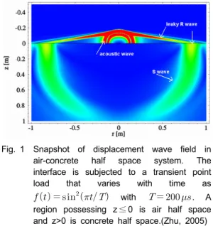
Fig. 1 Snapshot of displacement wave field in air-concrete half space system. The interface is subjected to a transient point load that varies with time as
with . A region possessing z ≤ 0 is air half space and z>0 is concrete half space.(Zhu, 2005) from being effective in field applications. One
major problem of the ultrasonic methods is the requirement of good contact between the sensor and tested concrete surface to obtain reliable data (Zhu, 2005). This problem can increase difficulties of the field implementation of the ultrasonic methods for the inspection of roadway concrete structures such as bridge decks and pavement. It is because the contact sensing needs a time- and labor-consuming surface preparation of rough concrete surface to mount the sensing units and which increase downtime of the structures during inspection period. A possible solution to this problem is to eliminate the need for physical contact between the sensor and tested structure. An obvious advantage of this non-contact sensing technique is which can greatly speed up the data collection in field and thus the damage detection process can be completed very rapidly.
In this article, recent developments in non-contact air-coupled sensing technique for rapid detection of damages in concrete structures are summarized to evoke interest, discussion and further developments on this technique to NDT research community in Korea. To this end, theoretical behind in non-contact sensing technique is briefly described and then some reported applications for damage detection of concrete structures are introduced. Finally, research efforts to overcome current limitations of the air-coupled sensing are provided. It is worth noting that the works in this summary have been published in the types of thesis, proceedings, and journals (Shin et al., 2009;
Zhu, 2005; Zhu and Popovics, 2005; Zhu and Popovics, 2007; Popovics et al., 2008). All published sources are cited in the text and listed in reference.
2. Technical Basis
In a fluid-solid half space system, the wave field in the solid is similar to that in the
(traction) free surface solid half space. All body waves, head waves, and Rayleigh waves exist in the solid. A distinct feature of the fluid-solid system from the free surface solid half space is that the propagating P-, S- and Rayleigh waves in the solid cause a small disturbance at the interface, resulting in out-of-plane surface motion. The resulting surface motion at each point causes an acoustic wave to “leak” into the surrounding fluid, assuming the fluid has lower acoustic impedance than the solid. It should be noted that this leaky wave exists only for stiff solid- light fluid cases, where the shear wave velocity of the solid is larger than the fluid velocity such as air-solid case. This type of wave can be excited by a transient point load that is normally applied to the solid at the interface. Fig. 1 shows the cross-sectional snapshot image of displacement field of fluid-solid half spaces (air-concrete) as generated by numerical simulation, at time t = 530 μs. In this simulation, material parameters are: for air
= 1.21(
),
= 343( ); and for concrete
= 2400(
),
= 4000( ),
. As clearly seen in this figure, wave
field in air is dominated by leaky Rayleigh
waves and direct acoustic waves nearby the
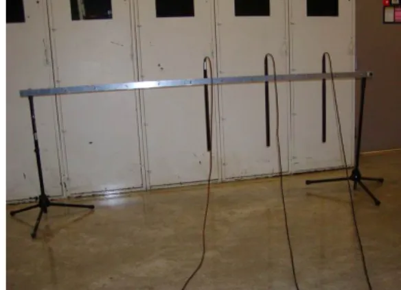
Fig. 2 Test setup showing microphones and the rack mount (Zhu and Popovics, 2005)
Fig. 3 Concrete floor slab with surface-opening cracks(Zhu and Popovics, 2005). Impact point source and three microphone receiver locations are shown at the top side
interface. Excitation efficiency of leaky Rayleigh waves for a point impact force with time duration of = 200 is about 0.1(Pa/kN), equivalent to a sound pressure level of 75 dB.
Such a pressure is large enough to be detected readily by an air-coupled sensor or microphone.
Theoretical basis in non-contact air-coupled sensing technique is set by the leaky waves excited by an impact load on concrete surface as described above. In the following chapters, two applications of non-contact air-coupled sensing for damage detection of concrete structures are summarized.
3. Introduction of Rapid Detection of Surface Opening Cracks in Concrete Structures
Non-contact air-coupled sensing not only improves test efficiency by eliminating the need for surface coupling, it also provides more useful information because of improved signal consistency by removing uncertainty in coupling condition. The latter advantage is more emphasized when wave attenuation information is needed for NDT of concrete structures. To utilize this merit in damage detection, the first application was done for detection of surface-opening cracks in concrete slab floor (Zhu and Popovics, 2005). The experiments were carried out at the Newmark Civil Engineering Laboratory (NCEL) of the University of Illinois at Urbana- Champaign.
3.1 Test Setup and Data Processing
The electronically-controlled impactor was used to generate repeatable point impulse forces.
The impulse force duration of the impactor is about 100 and the typical signal range generated by the impactor is 0-25(kHz). Three SHURE SM89 shot-gut type microphones were used as air-coupled sensors to detect leaky waves from the concrete floors. The microphones were mounted in line using a mounting system
that allows accurate placement of the sensors with regard to sensor separation and height from the test surface as shown in Fig. 2. Three microphones were used with 0.4 m spacing between each other and 0.67 m height from the test surface. The impact source is applied at a surface point along the line defined by the three aligned microphones, and the spacing between the source and the first microphone was 0.8 m.
The propagating leaky waves generated by the
source are detected by the microphones and are
sent to separate channels of a digital
oscilloscope. Each transient signal is collected
0 20 40 60 80 100 120 140 50
100
150
200
250
Fig. 4 Leaky surface waves y-scan energy ratio image(Zhu and Popovics, 2005)
0 20 40 60 80 100 120 140 160
40
60
80
100
120
140
160
180
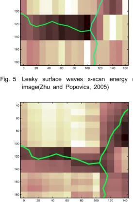
Fig. 5 Leaky surface waves x-scan energy ratio image(Zhu and Popovics, 2005)
0 20 40 60 80 100 120 140
40
60
80
100
120
140
160
180
Fig. 6 Leaky surface waves 2D-scan energy ratio image(Zhu and Popovics, 2005)
for duration of 5(ms) with 4096 digitized points.
An existing concrete floor slab in NCEL was used for testing. This slab has some regions that are apparently crack-free and other regions contain individual tightly-closed surface cracks.
A map of the floor slab specimen showing crack locations, microphone and impact positions and scan lines is shown in Fig. 3.
The attenuation was calculated based on leaky surface wave pulse energy ratio between the leaky wave signals detected by two adjacent microphones. The detailed procedures to calculate the energy ratio from captured wave signals can be found in reference . Here the results of each scan test are shown.
3.2 Damage Detection Results
Two 1-D scan tests were performed on the floor. First the microphone mounting frame was aligned along x direction (horizontal in Fig. 3) and moved in y direction, and a series of 30 parallel linear data sets were collected in the region (x = 0 – 160 cm) and (y = 0 – 290 cm), with 10 cm spacing in y direction between each data set. The x-scan test was performed in the region (x = 0 – 160 cm) and (y = 40 – 200 cm).
In this case, the microphone mounting frame was aligned along y-direction and moved in x-direction.
Fig. 4 shows the y-scan leaky surface wave
energy ratio images. The actual crack positions
are also superimposed on the images for
comparison. It can be seen that the energy ratio
image has clear and sharp contrast, and the dark
regions agree well with the actual crack
positions. The x-scan leaky surface wave energy
ratio image is shown in Fig. 5. It can be seen
that crack # 2 has been clearly identified by low
energy ratios, because the wave propagation
direction is perpendicular to the crack. In region
of (y = 140 – 180 cm), crack # 1 is nearly
parallel to wave propagation direction, so its is
difficult to identify the crack in image. However,
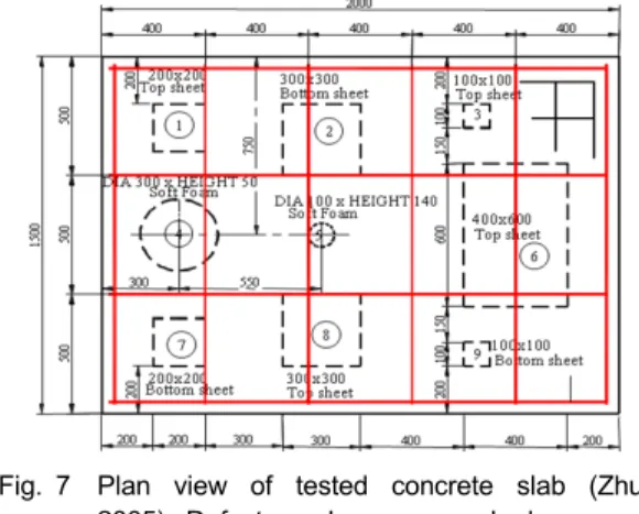
Fig. 7 Plan view of tested concrete slab (Zhu, 2005). Defect numbers are marked
the accuracy can be improved by combining two images obtained from the different scanning directions. Fig. 6 shows 2-D scan image obtained by taking summation of the normalized x-scan and y-scan parameters at the same position. The 2-D image clearly shows locations of all cracks as regions of low transmission.
From these results, we can conclude that leaky surface waves are sensitive to the existence of cracks when waves propagate across cracks and thus the non-contact air-coupled sensing technique can be effectively used for the detection of surface-opening cracks in the concrete slabs.
4. Introduction of Rapid Detection of Delaminations in Concrete Structures
Delamination in concrete structures is the most serious damage affecting service life of reinforced concrete bridge decks and slabs.
Delamination cracking generally propagates in the plane of the top reinforcing steel layer and parallel to the surface. The delamination will eventually propagate to the surface, causing large area spalling. Thus, it should be detected and evaluated at earlier time to reduce the cost to repair or rehabilitation. Many methods have been developed and suggested to detect this type of damage. Among them, impact-echo(IE) method is used for the implementation of air-coupled sensing technique. In this chapter, air-coupled IE is introduced for delamination detection in concrete structures (Zhu and Popovics, 2007).
4.1 Test Specimen and Air-Coupled Sensors
A concrete slab was prepared for the test of air-coupled IE. The slab specimen is nominally 0.25 m thick with lateral dimensions 1.5 m by 2.0 m. This slab contains artificial delaminations and voids with different sizes and depths as shown in Fig. 7. Artificial delaminations were simulated by embedding six double plastic
sheets. Three double sheets are located 60 mm below the surface (top sheet), and three are 200 mm below the top surface (bottom sheet).
The actual positions of plastic sheets were measured in the slab form before casting concrete.
To capture leaky wave signals from the IE test, a high sensitivity pre-polarized condenser type microphone is used (model name: PCB 377A1). Operational frequency range of the microphone is from 4 to 80 kHz at 2 dB. This microphone is able to detect higher frequencies corresponding to thickness of shallow delaminations. Moreover, its small size enables improved spatial resolution in IE scanning tests.
4.2 Point Test Results
Air-coupled IE tests were carried out over defect-free and defected regions on the slab specimen. The nine defects are numbered 1 to 9 from the left top corner to the right bottom corner as shown in Fig. 7. The sensor was positioned over the center of each defect when defect regions were tested. The source-to-sensor spacing is 5 cm, and the sensor was 3 cm above the concrete surface.
The air-coupled IE test results over defects
are listed in Table 1. Test points are grouped
according to type of defects. For example, test
points Nos. 1, 3, 6, and 8 are shallow
delaminations about 55 mm below the top
Table 1 Results from air-coupled IE point tests (Zhu and Popovics, 2007)
Point No.
Dominant Frequency
(kHz)
Tested Thickness
(mm)
Designed Thickness
(mm)
0 (solid) 7.81 252 250
1(shallow) 4.15 Flexural 55
3(shallow) 7.44 Flexural 55
6(shallow) 1.22 Flexural 55
8(shallow) 2.69 Flexural 55
4(void) 2.93 Flexural 75
5(void) 7.09 Flexural 50
2(deep) 10.62 185 190
7(deep) 10.62 185 195
9(deep) 7.69 - 190
Fig. 8 2D-image of the test slab built up using air-coupled IE data (Zhu and Popovics, 2007). The solid line indicates location of defects
surface. There is no defect at point No. 0 and the full thickness frequency 7.81 kHz was obtained. For shallow delaminations, the peak frequencies of air-coupled IE tests are lower than the full thickness frequency. In these cases, the peak frequencies do not correspond to the IE mode, but are set up by flexural modes. Flexural mode frequencies are affected by depth, areal size of defects and edge support conditions. With similar depth and support conditions, larger defect areas result in lower frequencies. The results show that shallow delaminations are easy to detect with air-coupled IE by observing peak frequencies shifting lower in the frequency spectra. Test points Nos 2, 7, and 9 are over deep delaminations at depth of 190 – 195 mm.
The measured IE peak frequencies at 10.62 kHz for points 2 and 7 give thickness of 185 mm, which agree well with the actual depth of 190 mm. However, no information was obtained for point No. 9, because the defect is too small and deep. The peak frequency slightly shifts to lower frequency range, which indicates possible presence of defects using the flexural mode response model.
4.3 Damage Imaging Results
A 2D-scanning test was conducted over the
entire area of the test slab to construct damage map. The measurement grid spacing is 10 cm in both directions (x and y); therefore in total of 261 signals were obtained, no data were collected along the slab edges. A 2D-matrix composed of the peak frequency of each signal’s amplitude spectrum at each point is used for image construction.
Fig. 8 shows a contour plot of the 2D-matrix
data. It can be seen that most defects are
identified in the image except for defect Nos. 3,
5, and 9. For large and shallow delaminations
and voids, i.e. defect No. 1, 4, 6, and 8, the
approximate areal size of damage regions are
also determined, and agree well with the actual
size and shape. For the small defects Nos. 3, 5,
and 9, the image shows slightly lower
frequencies than the normal full-thickness
frequency, which indicates very minor damage
level. The small defects can still be differentiated
from the surrounding solid regions. Hot spots
(high frequency) are observed over defect Nos. 2
and 7, which indicate existence of deep
delaminations. However, the size of damage
region cannot be accurately determined. The high
frequency corresponding to the depth of
delaminations is observed only in a small region
near the center of damaged area. The peak frequency shifts to a lower frequency range when the test point is over edges of defects. In addition to the designed nine defects, the regions marked ‘A’ and ‘B’ in the figure show a different color from the surrounding solid regions. The color represents a slightly higher frequency than the full-thickness frequency at 7.8 kHz. However, there are no designed defects in regions ‘A’ and ‘B’. Close examination of Fig. 7 reveals two steel chairs at locations ‘A’
and ‘B’, which were used to support the top layer rebars. Existence of these steel chairs affects the results of IE.
5. On-Going Research Effort
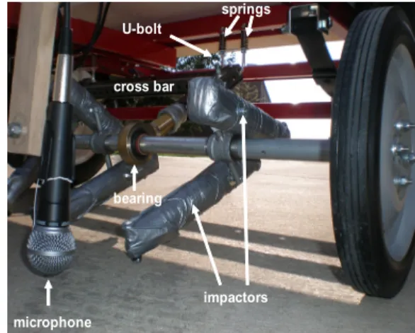
As shown in the previous chapter, air-coupled impact-echo testing can be used for detection and visualization of defects in concrete structures. However, still it has a significant drawback: it is a local, point contact method that cannot be implemented in a moving platform (Popovics et al., 2008). As a result, the inspection of a large structure is very time consuming and would normally require a significant disruption to the normal service of an existing a bridge in the case of a full deck survey. To overcome this problem, a project has been started for development of an innovative system which enables the powerful and cost effective impact-echo method to be carried out from a moving platform in an effective scanning configuration. The ultimate objective of this research is to design, fabricate and evaluate a prototype scanning system with an array of sensors in a wheeled frame configured to be towed behind a survey vehicle. The envisioned tool consist of an instrumented frame supporting up to 6 sources and 6 microphones connected to PC-based data acquisition system, which would scan a full traffic lane in a single pass. The testing prototype will be designed to work with minimal traffic control, optimally capable of
rapid scanning of in-service concrete bridge decks adjacent to active traffic lanes. Data will be collected using a custom-built PC-based acquisition system and interpretation will be simplified through the use of two-dimensional scan images, accurately identifying the location and character of defects in a deck “damage map.” The feasibility of future implementation of other more advanced analysis methods, such as guided wave dispersion analysis, will also be investigated. To achieve this goal, cost effective impact-echo method and the scanning platform are under development as shown in Fig. 9. By fusing the benefits of impact-echo with a scanning system, unparalleled bridge deck inspection capability will be provided to infrastructure management agencies.
microphone
impactors U-bolt
bearing cross bar
springs