Vol.14, No.4, pp.1-9 (2020)
Analysis of the Characteristics of an Aerospike Pintle Nozzle in terms of Stroke and Operating Pressure
Jeongjin Kim1,†
1Agency for Defense Development, the 4th R&D Institute, 1st Directorate
Abstract
The characteristics of an aerospike pintle nozzle system with excellent altitude compensation were analyzed using cold air testing. It was confirmed that reducing the stroke of the aerospike nozzle is effective in increasing the thrust. However, the results of additional numerical analysis indicated that the discharge coefficient factor was significantly lower at the maximum stroke. The Vena contracta due to the cowl reduction angle decreased the effective nozzle throat area at the maximum stroke and hindered expansion. Complementing the cowl design may thus increase the efficiency of a solid- propellant rocket engine that uses the aerospike pintle nozzle system.
Key Words: Aerospike Pintle Nozzle, Pintle Stroke, Operating Pressure
1. Introduction
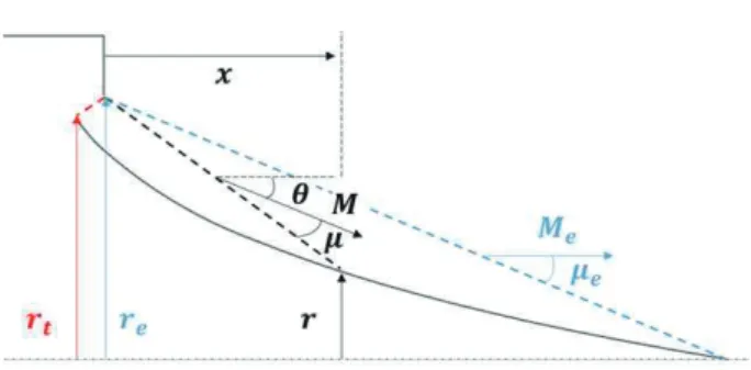
The aerospike pintle nozzle, which is illustrated in Fig. 1, is a reverse-shaped convergent-divergent rocket engine nozzle that assumes the role of the diverging section in a classic nozzle.
The higher the divergence ratio the greater the radius of the diverging section in a convergent-divergent nozzle and the smaller the tip of the aerospike nozzle.
The diverging section in a classic nozzle divides the air and the internal flow. Contrastively, aerospike nozzles that do not have an expander have been found to have excellent altitude compensation because the flow is not separated and changes in the shape of the exhaust gas depend only on the atmospheric pressure [1]. This design has been tested for practical application in liquid propellant rocket engines using both single [2,3] and cluster injectors [4].
The main focus of research into aerospike pintle nozzles has been concerned with liquid propellant rocket engines in which the injector flow rate can be controlled. Several studies have been carried out investigating the application of aerospike pintle nozzles to solid-propellant rocket engines [5]. Previous research has also included studies examining how changes to
the pintle shape and pintle nozzle stroke affect the thrust characteristics [6-8] and the heat transfer characteristics of a pintle nozzle [9], with the aim of controlling the thrust in solid- propellant rocket engines that use a convergent-divergent nozzle. However, no research has yet been conducted that examines the stroke-dependent characteristics of the aerospike pintle nozzle.
Solid propellant rocket engines require pintles for thrust control. The use of an aerospike that is capable of performing the function of a diverging section as a pintle in a solid- propellant rocket engine enables the construction of a lightweight system (as there is no need for a diverging section) and excellent altitude compensation. The application of the design to a real-time thrust control system such as the dual thrust and divert and altitude control system (DACS) would therefore ensure maximum efficiency.
Fig. 1 Nozzle Configuration
Received: Feb. 10, 2020 Revised: Mar. 09, 2020 Accepted: Jun. 04, 2020
† Corresponding Author
Tel: +82-42-821-0616, E-mail: [email protected]
Ⓒ The Society for Aerospace System Engineering
This study was conducted with the aim of designing an aerospike pintle nozzle that includes the characteristics of a dual-thrust solid-rocket engine. The applicability of the aerospike pintle actuation system was examined and discussed.
The characteristics of the aerospike pintle nozzle, which depend on the stroke and the operating pressure, were analyzed through cold air testing. Numerical analysis was performed in an effort to find the cause of the decrease in the discharge and thrust coefficients and to provide a means of improving the system by supplementing limitations in cold air testing, such as difficulties in measuring the flow rate or the pressure distribution on the wall.
2. Cold Air Test
2.1 Aerospike nozzle design
Fig. 2 shows the design concept for an aerospike nozzle that can enable an ideal expansion at any given exit Mach number
. Given that the working fluid is flowing parallel to the central axis when ideal expansion is reached (= 0) , the nozzle throat turn angle = ν() can be determined using the Prandtl-Meyer function, which is expressed in Eq. (1).
ν() = tan(− 1) (1)
− tan− 1
The area ratio ⁄ is a function of the Mach number at any
given position on the nozzle, as expressed in Eq. (2):
= 1 +
() (2)
The turn angle and Mach angle can also be obtained using Eq. (3):
= − , = sin(1 ⁄ ) (3) If the area of the nozzle throat is included in the design, the coordinates of the aerospike nozzle can be obtained using Eq.
(4).
= − (− )
()
, = () (4) The aerospike nozzle can therefore be verified to maintain efficiency compared to the simple cone-shaped nozzles that satisfy the Prandtl-Meyer expansion fan; not only in conditions that satisfy ideal expansion, but also across all NPR (nozzle pressure ratio) conditions [10].
The aerospike nozzle was designed with the intention of application in a dual-thrust solid-propellant rocket engine, in which the minimum thrust that allows smooth navigation is set
Fig. 2 Contour Calculation Model of the Aerospike Nozzle
Fig. 3 Cross-sectional Diagram of the Aerospike Nozzle and a maximum chamber pressure that is greater than that of a classic rocket engine is required to satisfy the target thrust ratio.
In this respect, two design points may be considered: a combination of minimum stroke (closed conditions; the minimum nozzle throat area) with the maximum NPR, and a combination of maximum stroke (open conditions; the maximum nozzle throat area) with the minimum NPR. These two points can be implemented into a design in which the stroke is increased by selecting a contour that expands ideally under maximum NPR and the stroke is reduced by selecting a contour that expands ideally at the minimum NPR. While altitude compensation ensures a certain efficiency under both methods, the maximum radius of the aerospike pintle head must invariably increase in the former case in order for the exhaust gas to rotate and expand sufficiently. Not only does this characteristic cause an increase in the weight of the system, but it also triggers a sudden change in the area of the nozzle throat that is due to oscillation in the actuator and the thermal expansion of the pintle, making it difficult to control the thrust or the pressure in the pintle rocket engine. An aerospike pintle nozzle contour that allows an ideal expansion at the point designed for minimum pressure was therefore selected.
The height of the pintle fastening and the radius of the pintle head were designed to be similar, as shown in Fig. 3. This offsets the compressive and tensile forces that occur within the system, allowing the pintle to be exposed to only compressive load under all conditions, thus precluding the possibility of the pintle touching the cowl and blocking the path of the flow,
which would be caused by a loss in actuator power during the subsequent actuation test.
Lastly, in the test case in which the aerospike pintle nozzle was applied with a single stroke, structural failure was observed in ether the pintle support shaft or the nozzle throat area on the cowl, as shown in Fig. 4 [2,3]. Therefore, the abrasion resistance was reinforced by using tungsten-rhenium (W-Re) to construct the entire pintle and the expected nozzle throat area on the cowl for the combustion test. A fillet was also applied to the nozzle throat area on the cowl in order to overcome the limitations that result from using this material in the manufacturing process, as shown in Fig. 5. The same design was applied in the cold air test, and the position of the nozzle throat on the cowl was checked prior to each test because its position changes according to the pintle stroke.
2.2 Test conditions
To ensure the repeatability of the combustion test, the same maximum and minimum nozzle throat areas were selected. An end burning grain was used to maintain the same chamber pressure throughout the entire combustion in order to test the solid-propellant rocket engine. The specific nozzle throat area that satisfies a specific thrust ratio was determined in advance, depending on the characteristics and length of the propellant and the diameter of the combustion chamber. The minimum cross-sectional area that can be geometrically formed according to the pintle stroke is shown in Fig. 6. The nozzle throat area and the stroke were rendered dimensionless by the exit area (= ) and the system limit stroke(20 mm), respectively.
This configuration can be used to define three different stroke conditions with maximum, minimum, and medium nozzle throat areas. Fig. 7 shows the pintle positions under closed (minimum nozzle throat area) and open (maximum nozzle throat area) conditions.
Fig. 4 Structural Failure of the Aerospike Nozzle [2,3]
Fig. 5 Round Fillet applied to the Cowl
The area ratio is obtained by comparing the exit area relative to the nozzle throat area under given stroke conditions with the radius of the cowl. First, the test conditions for different strokes were set based on the operating pressure, enabling ideal expansion in the ambient air. Different levels of pressure were added to include conditions including over-expansion, under- expansion, the ideal expansion for each stroke, double and triple (A) the ideal expansion pressure of the minimum stroke, and 0.3-fold (B) and 0.5-fold of the maximum stroke, as outlined in Table 1.
Fig. 6 Nozzle Throat Area according to the Pintle Stroke
Fig. 7 Cross-Section of the Aerospike Nozzle according to Changes in the Stroke
Table 1 Test Conditions
Stroke(mm) 3 6.1 12
NPR
2 - - (B)
Over
3 - Over Over
5 Over Over Ideal
11 Over Ideal Under
30 Ideal Under Under
55 Under Under Under
100 (A)
Under - -
Pa = 14.7 psia, Temperature = 300 K
However, certain combinations were omitted because of the difficulty in supplying air stably, which results from the performance limitations of the test apparatus. A cold air test was performed for 10 s under each test condition, and the segment from 5–9 s, during which time the internal pressure was kept constant, was assumed as a quasi-steady state for data analysis.
2.3 Test apparatus
The apparatus used in the cold air test consisted of a high- pressure supply tank (320 bar, 30 m3), a pressure control valve, a capacity control tank (200 bar, 0.75 m3) to maintain constant pressure, and the pintle system. Although air (up to 150 bar) was provided at high pressure, an operating pressure approximation equation was obtained through a preliminary test in order to control the resulting tank pressure.
The HBM load cell (2,000 kgf) and the DACELL load cell (500 kgf) were used to measure axial thrust and the pintle load, respectively. The air was injected through four evenly distributed inlets to minimize the flow disturbance inside the chamber. The pressure (Kulite ETM-375-5000) and temperature (K type) were measured at the positions given in Fig. 8. The flow according to each test condition was visualized using an average image obtained from measurements taken at 250 fps around the tip of the aerospike nozzle using a high- speed camera. The pintle test apparatus was modularized to accommodate different pintle shapes. As shown in Fig. 9, the accurate location of each test condition can be easily spotted using a jig and Vernier caliper, using the moment at which the pintle nozzle touches the cowl as the origin of the stroke.
Fig. 8 Experimental Setup
Fig. 9 Test Apparatus
2.4 Test results
Fig. 10 indicates that only compressive load is being applied under all thrust and pintle load conditions, as was intended.
Further, as shown in Fig. 11, the pintle load increases linearly as the operating pressure increases, which implies that the flow characteristics are maintained throughout the test. No flow separation was observed on the pintle surface because of the altitude compensation effect; thus, a linear prediction of the pintle load is available, which can be used for dynamic testing in the future.
Fig. 12 outlines the thrust coefficients, which depend on the operating pressure and stroke. The theoretical thrust coefficient assumes an ideal expansion and is delineated by the black line.
The thrust efficiency with a 3 mm stroke was generally highest under high-pressure conditions, and similar tendencies were observed regardless of the stroke used under low-pressure conditions.
For situations requiring a greater thrust than that associated with an NPR of 11, which is similar to the minimum operating pressure conditions of the dual-thrust rocket engine, increasing the operating pressure by lowering the stroke through pintle actuation (B) was found to be 14% more efficient than increasing the operating pressure via a single stroke (A). It can therefore be assumed that the aerospike pintle system can be applied in dual-thrust solid-rocket engines.
We also intended to test the system at thrusts lower than NPR 11, but no difference was observed in the efficiency whether the operating pressure was lowered by a single stroke or by increasing the stroke. However, low-NPR conditions are presumed to yield no specific tendencies and are strongly affected by error factors because of the low thrust generated by surpassing the recommended area for the supply of a constant flow rate. It is therefore necessary to design an aerospike pintle with a high reference NPR in order to examine its efficacy in the future.
Fig. 10 Pintle Load/Thrust Ratio
Fig. 11 Pintle Load with Different Strokes and NPR
Fig. 12 Thrust Coefficient with Different Strokes and NPR
Fig. 13 Averaged Experimental Schlieren Images
Fig. 13 shows images of the flow structures at different strokes and operating pressures. The conditions marked in red correspond to the area ratio-dependent ideal expansion pressure for each stroke condition. Despite the errors associated with using an approximation formula to adjust the control tank pressure, it is apparent that the exhaust gas is gathered towards the center under over-expanded conditions on the upper part of the reference NPR. In contrast, the exhaust gas passes the cowl and expands outwards in under-expanded conditions. The Schlieren images did not provide a view of the flow structure near the nozzle throat inside the cowl, and additional numerical analysis was therefore performed to complement the cold air test without the need for measuring the flow.
3. Numerical Analysis
3.1 Analysis model and boundary conditions
Three unstructured 2D grids were configured using approximately 120 000 cells with a maximum ortho skew of 1.6 e-1 that conformed with the stroke conditions. Fig. 14 illustrates the computational domain measuring 120R × 70R, based on the radius R of the exit cowl.
Numerical analysis was performed using the commercial software FLUENT set to the conditions “density-based typed,”
“steady,” “2D axisymmetric,” and “k-omega SST” as a turbulence model. Air (assumed to be an ideal gas) was used as a working fluid. The ambient pressure and operating pressure were applied to the pressure outlet (outer air) and pressure inlet (combustion chamber inlet), respectively.
Fig. 14 Computational Domain and Boundary Conditions of the Aerospike Nozzle [11]
Fig. 15 Two Grids of Different Densities that have been Magnified Near the Pintle Throat
To examine the grid size-dependency, a grid at a minimum of 1/3 the size of the initial grid was also configured for numerical analysis, as shown in Fig. 15. However, this configuration led to only minimal differences for thrust (-0.2%) and load (-0.26%) under an NPR of 30 and a stroke of 3 mm. Given the negligible differences, numerical analysis was therefore only performed using the initial grid in order to save time.
3.2 Analysis result
Since both points that form the nozzle throat have curved surfaces, it is necessary to check whether the nozzle throat has formed at the intended position for each stroke. The discharge correction factor was therefore computed using the theoretical discharge coefficient in Eq. (5), whereas the theoretical discharge coefficient was determined from the properties of the working fluid expressed in Eq. (6).
= ̇/() (5)
̇ : mass flow
: mean inlet pressure
: nozzle throat area
=
(6)
: specific gas constant
: mean inlet temperature γ : specific heat ratio
As shown in Figure 16, the discharge correction factor was found to be low at a 12 mm stroke, with the possibility of a decrease in the flow rate that was due to the reduced effective nozzle throat area as compared with the value assumed by the
Fig. 16 Discharge Coefficient Factor according to Stroke and NPR
design. Since measuring the flow rate was impossible with the limited equipment available, the thrust coefficient and the flow structure were compared instead of directly comparing the results of the numerical analysis with those of the cold air test.
Fig. 17 is a plot of the results of the thrust coefficient , which was computed by dividing the value for thrust calculated by the numerical analysis in Eq. (7) by . Despite errors, similar patterns were observed for the different stroke and NPR conditions.
= [̇ + ( − ) ] (7) + (− ) cos
: mean flow velocity at the exit along the central axis
: mean pressure at the exit
: post-exit pressure on the pintle surface
: ambient pressure
: angle with the central axis
Fig. 17 Comparison of the Thrust Coefficient by Experiment and Numerical Analysis.
Fig. 18 Flow Structure for NPR 30, Stroke 3 mm; (top) Numerical Shadow Graphs; (bottom) Averaged Experimental Schlieren Image
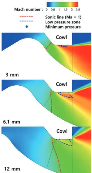
The flow structure was also verified to be similar to that shown in Fig. 18, which suggests that the characteristics found via the numerical analysis and the cold air test are similar in terms of thrust and flow structure and that the discharge coefficient is highly likely to be low in the cold air test. If the discharge coefficient is lower than that designed, in addition to a loss of thrust, the internal pressure surpasses the designed value in the actual combustion test. Therefore, the cause of the reduced discharge coefficient was analyzed.
Assuming that the internal flow that occurs during the cold air test is similar to that found via the results of numerical analysis, the pressure in the cylindrical part of the cowl exit was differentiated in the axial direction, as illustrated. Stroke- dependent differences were observed, but an adverse pressure gradient also appeared in the vicinity of the cowl exit, which is marked in red in Fig. 19. Fig. 20 shows a zone that is separated from the surrounding pressure field in which a relatively low pressure is maintained. This is ascribable to the Vena contracta phenomenon, in which relatively low pressure forms because the pressure cannot be recovered due to a large cowl convergence angle, which is unlike the surface of the aerospike pintle nozzle, while the accelerated flow is revolving around the nozzle throat area and the flow velocity is being increased.
Independent of the pintle, Vena contracta arises due to convergence at the cowl. However, as the maximum stroke was reached, the position of the lowest pressure at which the pressure gradient was adverse appeared in the forefront, followed by a long segment of pressure increase, thus intensifying its influence. On the contrary, the distortion of the sonic line (Ma=1), occurring in the geometric nozzle throat position, decreased towards the minimum stroke. Unlike the 12 mm stroke, the pintle was observed to approach the cowl under the minimum and medium strokes, affecting the flow and causing it to advance in a parallel direction to the cylindrical part of the cowl exit. Numerical analysis under the same pressure conditions, where only the converging part of the cowl was left after removing the pintle, yielded a discharge coefficient as low as 0.69. Furthermore, the minimum and medium strokes were positioned geometrically preceding the round fillet of the nozzle throat, i.e., before the occurrence of Vena contracta. On the other hand, at the maximum stroke of 12 mm, the nozzle throat is positioned geometrically past the round fillet. Vena contracta occurred in the vicinity of the designed nozzle throat, reducing the effective nozzle throat area, which appeared to narrow the effective nozzle throat area and lower the discharge coefficient.
Moreover, Eq. (8) reveals that the thrust is affected not only by the discharge coefficient but also by the exit velocity. In this respect, if the expansion is hindered by an adverse pressure gradient that causes the exit velocity to fall below the theoretical value because of the shape of the cowl, the thrust coefficient is also reduced. As discussed previously, unlike the experimental results in which no significant stroke-dependent differences
Fig. 19 Static Pressure Gradient along the Cylindrical Part of the Cowl
Fig. 20 Sonic (Mach number = 1) Line and Vena Contracta Location for an NPR of 30
were observed, detrimental effects were observed when the 12 mm stroke was used, as shown in Fig. 17. The results of the numerical analysis revealed the thrust coefficient of the 12 mm stroke to be highest under low-pressure conditions.
Therefore, although the cold air test requires revalidation, it may be assumed that lowering the operating pressure by increasing the stroke is highly likely to be more effective than lowering the operating pressure in a single stroke when a thrust lower than that associated with an NPR of 11 is required.
~̇~∙ (8)
: mean outlet flow velocity along the central axis
: discharge correction factor
: theoretical discharge coefficient
: velocity correction factor decided by the cowl shape
: theoretical outlet flow velocity along the central axis
It was verified that the adverse pressure gradient arises in the cylindrical part of the cowl by the effect of the Vena contracta generated along the convergence angle of the cowl, hindering proper expansion and resulting in a loss of thrust and a reduction in the effective nozzle throat area, especially under maximum stroke conditions. This suggests that the efficiency of the aerospike pintle system can be enhanced by reducing the divergence angle.
If the presence of the actuation system and the limit to the total length of the rocket engine make it difficult to control the convergence angle, the convergence angle can be reduced by selecting a contour that is designed with maximum NPR conditions. The nozzle throat area can be efficiently increased via a slight change in the stroke when the radius of the pintle head is increased. In this case, even under maximum stroke conditions, the distance between the pintle and the cowl is narrow enough to reduce the extent of the decrease in the discharge coefficient.
However, as mentioned above, an increase in the pintle head radius entails drawbacks. To improve the efficiency of the aerospike pintle system, it is therefore necessary to optimize the actuation pathways by investigating a large variety of stroke and NPR conditions at the contour designed to induce an ideal expansion under various NPR conditions.
4. Conclusion
A system capable of thrust control at a variety of altitudes through the altitude compensation effect can be constructed by applying the aerospike nozzle pintle to a solid-propellant rocket engine. In this study, an aerospike pintle nozzle was designed that takes into account the characteristics of a dual-thrust solid- propellant rocket engine, and a cold air test was performed to investigate the thrust and flow characteristics under different strokes and operating pressure conditions.
The cold air test did not result in verification of a tendency of reductions in the thrust as a result of the technical limitations of the test apparatus. However, the fact that the thrust coefficient can be efficiently increased by using an aerospike pintle system while enhancing thrust was verified.
As a result of the numerical analysis that was performed to complement the cold air test, which did not lend itself well to measuring and observing the flow rate and internal flow patterns, the discharge coefficient was verified to be the lowest under maximum stroke conditions. This can be ascribed to the Vena contracta effect, which occurred in the vicinity of the nozzle throat under maximum stroke, narrowing the efficient nozzle throat area. It was also verified that the adverse pressure gradient that incurred in the cylindrical part of the cowl thrust led to thrust loss.
In summary, it is expected that improving the cowl design and optimizing the actuation pathways in follow-up studies would enable the aerospike nozzle pintle system to perform with more efficient thrust control.
References**
[1] J. H. Ruf and P. K. McConnaughey, “The Plume Physics Behind Aerospike Nozzle Altitude Compensation and Slipstream Effect”, 33rd Joint Propulsion Conference &
Exhibit, Seattle, Washington, AIAA Paper no. 97-3217, July 1997.
[2] E. Besnard, H. H. Chen, T. Chen and J. Garvey, “Design, Manufacturing and Test of a Plug Nozzle Rocket Engine,”
38th AIAA/ASME/SAE/ASEE Joint Propulsion Conference
& Exhibit, Indianapolis, Indiana, AIAA-02-4038, July 2002.
[3] E. Besnard and J. Garvey, “Development and Flight- Testing of Liquid Propellant Aerospoke Engines,” 40th AIAA/ASME/SAE/ASEE Joint Propulsion Conference &
Exhibit, Fort Lauderdale, Florida, AIAA-2004-3354, July 2004.
[4] A. Kotake, D. B. Jones and I. Cannon, “Assembly of the XRS-2200 Linear Aerospike Rocket Engine,” 35th AIAA/ASME/SAE/ASEE Joint Propulsion Conference &
Exhibit, Los Angeles, California, AIAA-99-2183, June 1999.
[5] T. T. Bui, J. E. Murray, C. E. Rogers, S. Bartel, A. Cesaroni and M. Dennett, “Flight Research of an Aerospike Nozzle using High Power Solid Rockets,” 41th AIAA/ASME/SAE/ASEE Joint Propulsion Conference &
Exhibit, Tucson, Arizona, AIAA-2005-3797, July 2005.
[6] J. Heo, K. Jeong, H. Sung, “Numerical Study of the Dynamic Characteristics of Pintle Nozzles for Variable Thrust,” Journal of Propulsion and Power, vol. 31, no. 1, pp. 230-237, Jan. 2015.
[7] H. Sung, K. Jeong, J. Heo, “Performance characteristics of a pintle nozzle using the conformal sliding mesh technique,”
Aerospace Science and Technology, vol. 16, pp. 85-94, Feb.
2016.
[8] G. Lee and H. Sung, “Three-dimensional Effects of an Axi- symmetric Pintle Nozzle,” Journal of the Korean Society of Propulsion Engineers, vol. 22, no. 6, pp. 47-55, Dec.
2018.
[9] S. S. Park, Y. Moon, J. S. Kawk, “Numerical Analysis and 2-D Experiment of Heat Transfer Coefficient on the Pintle of a Controllable Thruster Nozzle,” Journal of Aerospace System Engineering, vol. 6, no. 4, pp. 24-28, Dec. 2012.
[10] J. Kim, S. Oh, J. Heo, D. Lee, “Analysis of the Flow Characteristics of Plug Nozzle for Cold Air Test with Pintle Shape and Operating Pressure,” Journal of the Korean Society of Propulsion Engineers, vol. 23, no. 3, pp. 28-34, June 2018.
[11] D. S. Ha, J. J. Kim, H. J. Kim, “Dynamic Characteristics of the Aerospike Shape Pintle Nozzle for Variable Thrust,”
AIAA Propulsion and Energy 2019 Forum, Indianapolis, IN, August 2019.