P2-30 / Y. -T. Lim
• IMID 2009 DIGEST
Abstract
In this paper, we explained characteristics of integral imaging microscope using point light source. To display the bio-medical information, which is captured as a form of the elemental images, using autostereoscopic displays, the characteristics analysis of three-dimensional information is required. For integral imaging microscope using point light source array, the elemental image capturing configuration has to satisfy a specific condition. We explain the condition to capture the elemental images and show the experimental results
1. Introduction
Integral Imaging(II), which is also called integral photography, is originally an autostereoscopic display technique with full parallax of the object[1]. Recently, various researches and applications of integral imaging are investigated and implemented[2]. Integral imaging microscope(IIM) is one of the applications using this technique. Previous researches for IIM showed successful reconstruction of the two dimensional images with different disparities and generation of the depth plane images[3]. However, conventional IIM has problem in observing the transparent specimen. Non-uniform surface of the object keeps off the depth plane image and reflection of light degrades the elemental images captured by the CCD, respectively. Hence, IIM using point light source(PLS) array is proper to capture the transparent object[4].
In this paper, we explain the condition to capture the elemental images in the PLS array based IIM and show the experimental results.
2. IIM using PLS array
IIM using PLS consists of PLS generation part and the overlapped image capturing part. Each part of IIM
uses infinity corrected optical system. Figure 1(a) shows PLS array generation part. On the plane 1, PLS is generated by micro lens array and these are focused again at the plane 2. Interval of each PLS on the plane 2 is given by 1 1 2 t o p f f m =
ϕ
, (1) where φ is pitch size of elemental lens, fo1 and ft1 are focal length of objective lens O1 and tube lens T1 respectively. Each PLS on the plane 2 passes through the specimen and is captured by a CCD as shown in Fig. 1(b). Each PLS on the plane 2 illuminates certain area of the specimen. Each point in the specimen is illuminated by multiple PLSs. From the geometrical analysis, overlapped area is given by1 1 2 ' ' t o o overlap f f f zh a = −ϕ , (2) where z is the distance between plane 2 and specimen,
fo2 is focal length of objective O2 and h'' is exit pupil
of objective lens O2 and tube lens T2. To generate overlapped area of the specimen, the distance between plane 2 and specimen z should satisfy the condition given by 2 1 2 1 2 t o m o f f f z f > > , (3) where fm is focal length of micro lens array. By substituting equation (2) into (3), we get
⎟⎟ ⎠ ⎞ ⎜⎜ ⎝ ⎛ − > > − 1 1 1 1 2 1 2 2 1 1 1 ) ( t o overlap o t m o m o t f f a f f f f f f f ϕ ϕ . (4)
For capturing the elemental images, the gap between plane 2 and CCD, g, should be given by
Characteristics of integral imaging microscope using
point light source array
Young-Tae Lim*, Jae-Hyeung Park, Ki-Chul Kwon, and Nam Kim
College of Electrical & Computer Engineering, Chungbuk National University, Cheong-ju, Korea
Tel.:82-43-267-2578, E-mail: [email protected]
P2-30 / Y. -T. Lim IMID 2009 DIGEST • , ) ( 12 2 1 2 1 2 2 1 1 m o o m t o t t o m f f f f zf f f f f kzf g + − =
ϕ
ϕ
(5)
where k is the size of CCD.
(a) Part of generating point light source array
(b) Part of capturing the overlapped image Fig. 1. Structure of integral imaging microscope
using point light source array
3. Experiment
In our experiment, we used the 10x objective lens for focusing point light source array and the 20x objective lens for capturing the elemental image. The object is transparent ovary of plant specimen. Pitch size of micro lens array is 0.125um and focal length of micro lens array is 2.4mm. Focal length of ft1, fo1 and fo2 are
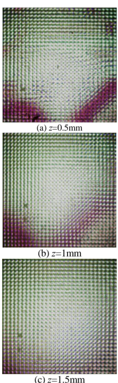
200mm, 20mm and 10mm, respectively. Pitch size of CCD is 5.9um. From the equation (5), we set the g to 220um and captured elemental images with z =0.5 to z=1.5mm. Captured elemental images are shown in Fig. 2.
(a) z=0.5mm
(b) z=1mm
(c) z=1.5mm
Fig. 2. Captured elemental image with different z
4. Conclusion
In this paper, we explained characteristics of IIM using PLS array. From the results, we can find that elemental images corresponding to the overlapped area on the specimen are related with equation (4) and (5). This work provides a theoretical basis for implementing the PLS based IIM combined with integral imaging display system for the bio-medical transparent specimen.
Acknowledgement
“This work was supported by the grant of the Korean Ministry of Education, Science and Technology(The Regional Core Research Program/Chungbuk BIT Research-Oriented University Consortium)”
P2-30 / Y. -T. Lim
• IMID 2009 DIGEST
5. References
1. B. Lee, J.-H Park and S.-W. Min, Digital holography and Three-Dimensional Display, Springer, New York, p.333 (2006).
2. Y.-T. Lim, J.-H. Park, K. C. Kwon and N. Kim, DH
2009, DWB14, (2009).
3. Y.-T. Lim, J.-H. Park, N. Kim and K. C. Kwon,
Proc. of SPIE, 7237-65, (2009).
4. Y.-T. Lim, J.-H. Park, K. C. Kwon and N. Kim,