접수일: 2018년 5월 31일, 게재승인일: 2018년 6월 10일 책임저자: 이광재, 전주시 완산구 서원로 365
뿸 54987, 예수병원 재활의학과
Tel: 063-230-1460, Fax: 063-282-3385 E-mail: rytt@naver.com
퇴행성 척추질환과 요추 초음파 유도 중재시술
예수병원 재활의학과
윤용순ㆍ이광재
Degenerative Diseases and Ultrasound- guided Intervention in Lumbar Spine
Yong-Soon Yoon, M.D., Ph.D. and Kwang Jae Lee, M.D., Ph.D., RMSK
Department of Rehabilitation Medicine, Presbyterian Medical Center (Jesus Hospital), Jeonju, Korea
Degenerative disease of the spine affects all people and several distinct degenerative processes can be observed.
These processes are associated with characteristic radio- graphic and pathologic abnormalities. Intervertebral os- teochondrosis, spondylosis deformans, osteoarthritis of the facet joint, and diffuse idiopathic skeletal hyperostosis (DISH) are the major forms of degenerative diseases in lumbar spine. Ultrasound is frequently used to guide several lumbar procedures before and after operation, or just for nerve block and intra-articular injection even though fluoro- scopy have been used preferentially in interventional proce- dures due to well visualization of the needle and of the spreading of the injections. However, more and more clini- cians have applied ultrasound-guided intervention with sev- eral advantages, such as no radiation exposure, relatively inexpensive in cost, and smaller space in occupancy. We reviewed sonoanatomy and well established several ultra- sound-guided interventions in lumbar spine, such as medial branch block, facet joint injection, caudal block, and lumbar epidural block. (Clinical Pain 2018;17:6-15)
Key Words: Degenerative diseases, Lumbar vertebrae, Ultraso- nography, Interventions
서 론
인간은 누구나 나이가 들어감에 따라 근골격계 조직의 퇴행성 변화를 거치며 척추 또한 예외가 될 수 없다.1 몇몇 저자들은 80%의 사람에서 일생에 한 번 이상의 요통을 겪
는다고 보고하였는데 퇴행성 변화를 진행시키는 여러 인자 들 가운데 가장 중요한 것은 외상으로서 급성 외상, 만성적 인 반복 외상, 만성적인 과부하 모두를 포함한다.2
위 아래 척추는 크게 추간판과 척추후관절로 연결되어 있고 수 많은 인대와 근육이 그 주변을 감싸고 있어 이 모 두에서 퇴행성 변화가 일어나지만 더 깊이 들어가보면 더 욱 변화가 심한 또는 근본이 되는 해부학적 구조물을 구별 할 수가 있어 혹자는 추간판이 속한 연골성 관절연결 (cartilaginous articulation), 척추후관절이 중심이 되는 활막 성 관절연결(synovial articulation), 기타 인대, 근육과 힘줄 이 관여하는 섬유성 관절연결(fibrous articulation)에 의한 퇴행성 척추질환과 이에 따른 합병증으로 분류하였고,3 혹 자는 추간판의 퇴행(intervertebral disc degeneration), 관절 의 퇴행(joint degeneration), 신경 압박과 파행(nerve com- pression and spinal claudication), 시상면 상의 불균형 (sagittal imbalance)으로 구분하여 설명하였다.2 본 종설에 서는 전자의 분류를 기준으로 단순 방사선 사진으로 구별 되는 추간판 퇴행의 대표적인 두 질환인 intervertebral os- teochondrosis와 spondylosis deformans, 활막관절의 퇴행 성 변화인 osteoarthritis (of the facet joint)와 후방조직의 변성, 그리고 섬유성 관절연결의 퇴행성 변화 중 하나인 DISH (diffuse idiopathic skeletal hyperostosis)로 나누어 설 명하고, 추가로 추간판탈출증(disc herniation)에 대하여 설 명하고자 한다.
영상학적 진단은 병력 청취와 이학적 검사가 반드시 선 행되어야 하며, 정확한 진단의 바탕 위에 치료 방법, 부위 등을 결정해야 한다. 요추부 초음파의 가장 흔한 적응증은 초음파 유도 중재시술로서 초음파 유도 내측지 신경차단술 (medial branch block),4 척추후관절 관절내 주사(facet joint injection),4-6 꼬리블록(caudal block)4이 비교적 널리 알려 져 있고, 정확한 바늘 끝의 위치 확인이 어려운 점과 초음파 로 요추부의 깊은 해부학적 구조를 제대로 파악할 수 없는 점 등으로 보편화되지는 않았지만 경막외 신경차단술이 점 차 늘고 있다.7,8 요추부의 초음파 유도 중재시술이 향후 좀 더 보편화 될 것으로 기대하며 기존의 논문들을 바탕으로 요추부의 기본적인 해부학적인 이해와 더불어 각각의 초음 파 소견과 시술법 등에 대하여 정리해 보고자 한다. 모든 초음파 검사 및 중재시술은 필립스사의 iU22의 5-1 MHz
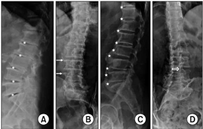
Fig. 1. Simple lateral (A, C) and oblique (B, D) X-ray findings of intervertebral osteochondrosis (A), spondylosis deformans (B), diffuse idiopathic skeletal hyperostosis (DISH) (C), and os- teoarthritis of the facet joint (D). Note the bone sclerosis, disc space loss, and vacuum phenomena (asterisks) in (A), marginal osteophytes (arrows) with relatively preserved disc space in (B), flowing ossification (stars) with normal disc space in (C), and joint space narrowing of L3-4 facet joint (void arrow) in (D).
곡면 탐촉자(curved transducer), 12-5 MHz 선형 탐촉자 (linear transducer)와 EPIQ evolution 4.0의 18-4 MHz 선형 탐촉자를 이용하였다.
본 론
1. 해부학적 구조
요추 5번의 천추화(sacralization of L5) 또는 천추 1번의 요추화(lumbarization of S1)와 같은 Lumbosacral transi- tional vertebra가 있지만 일반적으로 요추는 다섯 개의 척 추뼈(lumbar vertebra)로 구성되어 있고 척추체(vertebral body) 사이에 추간판(intervertebral disc)이 위치하여 위아 래 척추가 연결되고 뒤쪽으로는 윤활관절(synovial joint)인 척추후관절(facet joint, zygapophyseal joint)에 의해 위아래 척추가 서로 연결되어 있다. 척추후방조직은 척추후관절과 더불어 황색인대(ligamentum flavum), 극간인대(interspinous ligament), 극돌기(spinous process) 등을 일컫는다. 요추에 서 척추후관절의 관절면은 전내측을 향하고 있어 퇴행성 변화에 의해 요추의 전방 또는 후방전위가 나타나기 쉽다.9
추간판은 척추를 지탱하는 주된 구조물이며 동시에 굴 곡, 신전 및 회전 등 어느 정도의 움직임도 허용하는데 섬유 륜(annulus fibrosus)이라고 하는 15∼25 겹의 탄성 콜라겐 이 동심원의 합판 구조로 외부를 둘러싸서 내측에서 전달 된 충격을 막아내고 종인대(longitudinal ligament)가 앞과 뒤에서 일부를 감싸고 있으며 섬유륜의 내측에 젤라틴 성 분의 수핵(nucleus pulposus)이 있어 충격 흡수를 하는데 이 수핵의 물과 프로테오글리칸(proteoglycan) 성분은 나이가 들어감에 따라 감소한다.10 추간판은 혈관이 없어 대부분 확산에 의해서 영양분을 공급받지만 외측의 섬유륜은 혈관 을 통해 영양분을 공급받는다. 신경 또한 이와 비슷하게 섬 유륜의 바깥부분 1/3에만 있는데 특히 후방은 동굴척추신 경(sinuvertebral nerve)에 의해 신경지배를 받으며 통증을 전달하는 주요 신경이 된다.11
2. 요추의 퇴행성 질환
(Degenerative disorders of the lumbar spine) 요추부에 나타나는 퇴행성 변화는 추간판의 변성, 척추 후관절의 관절염, 척추주위 연부조직의 변화와 관련이 있 으며 외래에서 간단하게 촬영할 수 있는 단순 X-선 사진상 의 소견에 따라 intervertebral osteochondrosis, spondylosis deformans, osteoarthritis of the facet joint, 그리고 DISH로 나눌 수 있다.
Intervertebral osteochondrosis는 단순 X-선 소견상 골경 화(bone sclerosis), 추간판 높이 감소(disc space loss), 그리 고 추간판 변성에 의해 공기가 차는 진공 현상(vacuum
phenomenon) 등의 소견을 보인다(Fig. 1A). 물과 프리테오 글리칸 성분이 소실됨에 따라 수핵이 누렇게 변하고 (yellow-brown discoloration), 균열과 틈이 생기고 커져 이 갈라진 공간에 음압이 생기면 그 안으로 질소가스가 차며 섬유륜의 파열이 동반되면 가스가 추간판을 지나 주변 조 직으로도 퍼진다. 수핵이 수직으로 갈라져 척추체의 연골 하 골(subchondral bone) 또는 척추체 내로도 확장될 수 있 으며 이렇게 추간판이나 척추체에서 공기음영이 관찰되면 척추감염이나 종양일 가능성은 매우 낮다.3
Spondylosis deformans는 방사선 소견 상 모서리뼈돌기 (marginal osteophyte)가 관찰되는 것이 대표적인 특징이며 추간판 높이는 정상이거나 약간 감소된 정도다(Fig. 1B).
모서리뼈돌기는 앞쪽 말단부 섬유륜의 rim tear에 의해 수 핵이 전체적으로 앞쪽으로 밀리며, 앞쪽 횡인대(anterior longitudinal ligament)의 내측 섬유와 이것에 붙어있는 Sharfey’s fiber에 견인력(traction force)이 가해지고 discov- ertebral junction에서 수 mm 떨어진 곳에 부착된 이 Sharfey’s fiber를 따라 처음에는 수평방향으로, 그리고 더 자라면서 수직방향으로 갈고리같이 자란다.3 모서리뼈돌기 는 강직성 척추염에서 관찰되는 인대골증식체(syndesmo- phyte), 건선관절염과 반응관절염(라이터증후군)에서 보이 는 척추주위골화(paravertebral ossification), 그리고 DISH 에서 관찰되는 물결모양의 골화(flowing ossification) 등과 구별해야 한다.1
요추의 Osteoarthritis of the facet joint (척추후관절염)은
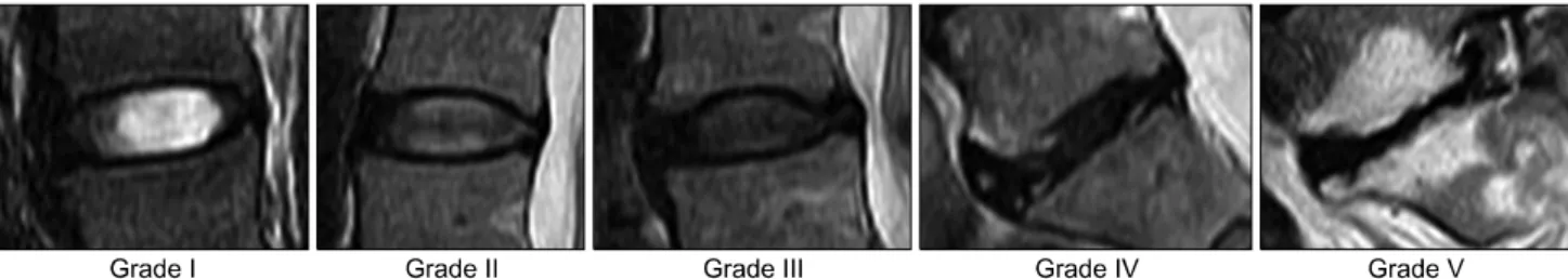
Fig. 2. Pfirrmann grading system for the assessment of lumbar disc degeneration. Grade I: The structure of the disc is homogeneous, with high signal intensity (SI) and a normal disc height. Grade II: The structure of the disc is inhomogeneous, with a high SI. The distinction between nucleus and annulus is clear, and the disc height is normal, with or without horizontal grey bands. Grade III:
The structure of the disc is inhomogeneous, with an intermediate grey SI. The distinction between nucleus and annulus is unclear, and the disc height is normal or slightly decreased. Grade IV: The structure of the disc is inhomogeneous, with low (dark grey) SI. The distinction between nucleus and annulus is lost, and the disc height is normal or moderately decreased. Grade V: The structure of the disc is inhomogeneous, with low (black) SI. The distinction between nucleus and annulus is lost, and the disc space is collapsed.
Grading is performed on T2-weighted sagittal images.
관절 방향에 따라 사위(oblique view) 촬영으로 잘 관찰되 며(Fig. 1D) 다른 활막관절의 퇴행성 관절염 같이 뼈돌기 형성(osteophyte formation), 관절간격 감소(joint space nar- rowing), 연골하골 경화(subchondral sclerosis), 연골하골 침식(subchondral erosion) 등이 보이며 때로는 관절삼출액 이 차거나 주변에 낭종을 형성하기도 한다.1,3 이러한 관절 염은 추간판 변성이나 탈출에 따라 후관절과 주변조직의 기계적인 압력이 증가되어 발생하고 퇴행성 척추전위증 (degenerative spondylolisthesis)의 원인이 된다. 동시에 황 색인데, 극간인대, 극돌기 같은 후방 조직의 퇴행 변화도 동반된다.12 후관절을 포함한 후방 조직의 풍부한 신경지배 로 환자를 괴롭히는 통증 등 다양한 임상양상을 보이며 2차 적으로 척수강 내 신경이나 신경근 등을 압박할 수도 있다.
DISH는 70대 이상의 노년층에서 원인을 알 수 없이 척 추 또는 척추 외 인대나 건의 골부착부에 미만성으로 골화 또는 석회화가 나타나는 질환으로 방사선 소견 상 추간판 이 있는 부분이 돌출되고 척추체의 중간 부분이 들어간 물 결모양의 골화(flowing ossification)가 연속된 네 개 이상의 척추 전측방에서 관찰된다(Fig. 1C). 흉추의 골화가 가장 흔하지만 경추나 요추의 골화도 드물지 않고 특히 경추의 후종인대골화증(OPLL, ossification of posterior spinal lig- ament)이 흔히 동반된다.3 관절운동범위의 제한이 주증상 이며 통증은 심하지 않다. 추간판의 높이는 대체로 유지되 고 양쪽 천장관절도 정상 소견을 보여 다른 퇴행성 척추질 환이나 강직성 척추염과 구별된다.
퇴행성 변화에 따라 2차적으로 위쪽 척추체가 앞쪽으로 이동하는 퇴행성 전방전위증(degenerative spondylolisthesis) 과 같은 불안정성이 초래될 수 있으며 중심관(central canal) 의 협착이 두드러지고 신경공(neural foramen) 또한 협착 소견이 관찰된다. 전방전위증은 단순 방사선 소견 상 아래
척추체의 윗면을 4등분하여 1/4씩 전위의 단계를 나누어 grade 1∼4로 구분한다.
3. 추간판탈출증(Herniated intervertebral disc, HIVD) 단순 X-선 사진 상 관찰되는 퇴행성 척추질환은 추간판 의 퇴행변화를 동반하고 있어 환자의 증상과 연관된 추간 판의 변성이나 탈출, 2차적인 신경압박 등에 대한 평가를 위해서 현재까지 가장 유용한 검사는 자기공명영상촬영 (MRI)이며 필요한 경우 근전도 검사도 시행한다.
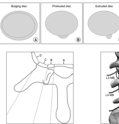
요추의 추간판의 변성은 MR T2 강조영상에서 저신호강 도 음영으로 나타나며 2001년 Pfirrmann 등13이 다섯 단계 로 나눈 분류를 많이 사용한다(Fig. 2). 섬유륜은 추간판 내 에서 concentric tear, radial tear, transverse (rim) tear 등 여 러 가지 형태로 찢어질 수 있는데 이 중 radial tear는 추간 판내장증(internal disc disruption, IDD)의 주된 원인으로 추간판성 요통(discogenic back pain)을 야기한다. 추간판이 정상 해부학적 범위 밖에 있는 것을 추간판탈출증(herni- ated intervertebral disc, HIVD)라고 하는데 외연이 50% 이 상 돌출된 경우는 따로 bulging disc로(Fig. 3A), 외연이 50% 이내로 돌출된 경우에만 herniated disc (또는 disc her- niation)이라고 명명하며 척추체 내로 탈출한 경우는 intra- vertebral herniation (Schmorl’s node)라고 정의한다.12,14 herniated disc는 축상영상(axial image)이나 시상영상(sagittal image)에서 모두, 돌출된 추간판 직경이 돌출 base의 길이 보다 작은 경우 protrusion (protruded disc)로(Fig. 3B), 큰 경우 extrusion (extruded disc)로(Fig. 3C) 구분하며 원래의 추간판에서 분리된 조각(sequestration)의 경우도 extrusion 에 포함된다. 축상면(axial plane)에서 탈출된 추간판의 방 향에 따라 central, subarticular, foraminal, extraforaminal (far lateral) zone으로 구분하며(Fig. 4) 일반적으로 central
Fig. 3. Schematic drawings of the bulging disc (A), protruded disc (B), and extruded disc (C).
Fig. 4. Schematic drawing of zones of the disc herniation in ax- ial plane. The direction of the disc herniation direction is div- ided into 4 zones; central (A), subarticular (B), foraminal (C), and extraforaminal (far lateral) (D) zones according to the ana- tomical structures. Subarticular zone (B) is from the medial edge of the facet articulations to the borders of the pedicle, and fora- minal zone (C) is between anterior and posterior borders of the pedicle. Most disc herniation will occupy more than one zone.
Fig. 5. Schematic picture of the third and fourth medial branches. Note that dual innervations for one facet joint. MB, medial branch; FJ, facet joint.
이나 subarticular zone으로의 탈출은 아래 요추 신경근(요 추 4∼5번 추간판의 경우 요추 5번 신경근)을, foraminal 이나 extraforaminal (far lateral) zone으로의 탈출은 신경공 을 통과하는 윗 요추 신경근(요추 4∼5번 추간판의 경우 요추 4번 신경근)을 누르기 때문에 이러한 구분이 중요하 다. 시상면(sagittal plane)에서도 추간판과 척추경(pedicle) 을 기준으로 disc/ infrapedicle/ pedicle/ suprapedicle level 로 나누어 구분한다.
요추 중심관 협착(central stenosis)에 대하여 2011년 Lee 등15은 협착이 없는 경우 grade 0, 협착되어 있지만 경미하 고 마미총(cauda equine)이 분명하게 서로 분리돼 보이는 경우 grade 1, 중등도의 협착으로 마미총 일부가 뭉쳐서 보
이는 경우 grade 2, 모든 마미총이 하나의 덩어리로 보이는 심한 협착을 grade 3로 분류하였고, 신경공 협착(neural for- aminal stenosis)에 대하여 Lee 등16은 정상을 grade 0, 어느 방향에서건 신경근 주위 지방조직(perineural fat)이 눌려서 좁아져 있으면 grade 1 (mild), 신경근 주위 지방조직이 네 방향 모두에서 눌려서 좁아져 있으면 grade 2 (moderate), 지방조직의 눌림 정도와는 상관없이 신경근 자체가 눌려 모양이 변형되어 있으면 grade 3 (severe)로 각각 분류하였다.
4. 초음파 유도 중재시술
1) 내측지 신경차단술(Medial branch block)과 척추후 관절 주사(Facet joint injection): 척추신경의 후방 일차 분 지(posterior primary ramus)에서 유래하는 내측지(medial branch)가 척추후관절의 신경을 담당하기 때문에 척추후관 절염 등 후관절 증후군17 때 선택적으로 내측지 신경차단술 또는 척추후관절 주사치료를 시행한다. 하나의 척추후관절
Table 1. Comparison between Medial Branch Block and Facet Joint Injection
Medial branch block Facet joint injection
Small amount of injectable solution Large amount of injectable solution
More effective Effective
More selective and less destructive Direct damage to the joint and adjacent structures 2 target points for 1 facet joint 1 target point for 1 facet joint
Deeper injection- more difficult More superficial injection
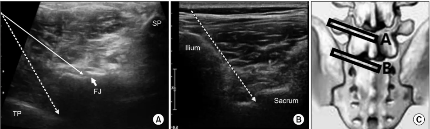
Fig. 6. Short-axis US images from the lumbar vertebra (A) with 5-1 MHz curved transducer and from the sacrum (B) with 12-5 MHz linear transducer show the needle direction for the medial branch block (thick dotted arrows) and for the facet injection (thin straight arrow) and transducer positions which are depicted in schematic picture. TP: transverse process, FJ: facet joint, SP: spinous process.
에 두 개의 내측지가 분포(예를 들어 요추 4∼5번 사이 후 관절의 경우, 요추 3번 내측지와 요추 4번 내측지가 분포) 하므로(Fig. 5) 내측지 신경차단술은 두 부위에서 시행한 다. 초음파 유도 중재시술의 효과가 방사선 투시 유도 중재 시술(fluoroscopy-guided intervention)과 비교해서 차이가 없고17 초음파를 사용할 경우 방사선 피폭 없이 외래에서 비교적 작은 공간에서 시행할 수 있다. 척추후관절 주사는 선형 탐촉자(linear probe)로도 시행할 수 있으나 일반적으 로 요추부의 중재시술은 곡면 탐촉자(curved probe)를 이용 한다. 우선 요추의 극돌기가 있는 하부 요추의 중앙에 장축 으로(long-axis) 탐촉자를 위치시켜 척추의 레벨을 정하는 데, 하부 요추로 갈수록 조금씩 깊어지는 언덕 모양 극돌기 들의 반복된 영상을 찾고 이와 달리 완만한 오르막길처럼 보이는 중앙천골능선(median sacral crest)을 확인하여 요추 5번과 천추의 경계를 구분하고 각각의 극돌기 영상을 중심 으로 단축(short-axis)으로 탐촉자를 돌려 극돌기, 수평의 고에코 구조물인 척추판(lamina)과 이와 연결된 척추후관 절, 그리고 또 다시 더 외측에 깊숙이 보이는 또 하나의 수 평 고에코 구조물인 횡돌기를 확인한 후 척추후관절을 목 표로 척추후관절 주사치료를 할 수 있고, 횡돌기가 시작되
는 부위를 목표로 내측지 차단술을 할 수 있다(Fig. 6A).
내측지 차단술의 경우 한 레벨 아래에서 한 번 더 주사해야 한다. 요추 5번과 천추 1번 사이 척추후관절의 경우 요추 5번에서, 그리고 천추 뒷면의 위관절돌기(superior articular process) 시작 부위의 외측에서(Fig. 6B) 한 번 더 주사한다.
두 가지 주사치료에 대한 비교는 표로 정리하였다(Table 1).
2) 꼬리뼈 신경차단술(꼬리블록, 미추차단술, Caudal block): 꼬리블록은 추간판 탈출에 의한 경막 또는 신경근 압박으로 발생한 요통, 허리 수술 후 통증, 척추관 협착증에 의한 요통 등 여러 원인에 의한 요통 및 하지 방사통을 경 감시키기 위해 시행한다.19 항문열(anal cleft)의 근위부에서 천골틈새(sacral hiatus)를 통해 천골관(sacral canal) 속으로 주사하며 경막외 신경성형술(RACZ)의 도관을 삽입하는 부위도 이 부위로서 정확한 위치 확인을 위해 초음파가 유 용하게 사용되며 주로 선형 탐촉자를 사용한다. 양쪽 Dimple of Venus를 이은 선을 기준으로 아래쪽으로 정삼각 형을 그리면 꼭지점에 해당하는 부위를 표시하고 이 곳에 단축으로 탐촉자를 대면 중앙에 천골틈새가, 양 옆으로 불 쑥 솟아있는 골조직인 천골각(sacral cornu)이 보이며, 탐촉 자를 조금씩 내리면 천골각은 얇아지고 천골틈새는 넓어지
Fig. 7. Short-axis (A) and Long-axis (C) US images with 12-5 MHz linear transducer and corresponding schematic drawings (B, D) of the sacrum. Needle (arrowheads in C and black straight line in D) passes into the sacral canal through the sacral hiatus.
고 얕아지고 탐촉자를 조금씩 올리면 천골각은 두꺼워지고 천골틈새는 좁고 깊어지다가 골조직으로 막혀 없어지는데 이 천골틈새가 좁고 깊은 부분이 초음파로 주사바늘을 관 찰할 수 있는 가장 근위부가 된다(Fig. 7A, B). 다시 탐촉자 를 장축으로 돌려 뼈로 덮인 천골의 후면과 이 뼈에서 이어 진 천미골 인대(sacrococcygeal ligament)를 확인하고 이 인 대의 아래쪽에서 보이는 골조직인 천골의 기저부를 확인하 고 인대를 뚫고 천골 후면의 아래쪽 천골틈새로 주사바늘 을 삽입한다(Fig. 7C, D). 주사액을 넣기 전 반드시 음압을 가해 혈액의 역류 여부를 확인하고 혈액의 역류가 관찰되 면 주사바늘의 위치를 조정한 후 반복하여 혈액의 역류가 없으면 주사한다. 2014년 Fukazawa 등20은 꼬리블록 시 혈 관 내 주사(accidental intravascular injection)가 41.7%
(n=211)에서 관찰되었다고 보고할 정도로 혈관 내 주사가 빈번한데 초음파로는 확인이 되지 않는 단점이 있다. 이 연 구에 의하면 통증 지속 기간이 길수록 그리고 신경근 압박 증상이 있는 경우 혈관 내 주사가 빈번하다고 분석하며 만 성적인 염증으로 인한 신생혈관의 증가로 인한 것으로 생 각하였다. 그리고 심호흡 정지(cardiopulmonary arrest), 척 수 경색(spinal cord infarction), 하반신 마비(paraplegia) 등
위중한 합병증의 발생이 보고되어 있어 복용 약제 및 기저 질환에 대한 파악이 필수적이며 환자 선택 및 시술 시 신중 한 접근이 필요하다.
3) 경막외 신경차단술(Epidural block): 경막외 신경차 단술은 추간판 탈출증에 의한 경막 또는 신경근 압박 등 척추주위 조직의 염증과 통증을 조절하기 위하여 시행하 며, 허리 수술 전후 통증 조절을 위해서도 시행한다. 뒤쪽 경막외 공간으로 접근하는 정중옆 척추판 사이 접근법 (Paramedian interlaminar approach)과 신경근이 나오는 신 경공 속(transforaminal, 경추간공) 공간으로 접근하는 신경 근옆 접근법(pararadicular/periradicular approach)이 있으며 실시간 초음파를 이용할 경우 전자는 장축으로 탐촉자를 위치시켜 시술을 하지만, 후자의 경우 장축 및 단축 영상을 이용한 시술법이 모두 보고되어 있고 장축 영상 유도 시 pararadicular, 단축 영상 유도 시 periradicular라고 나누기 도 한다. 깊은 시술 목표지점과 낮은 해상도, 해부학적인 요인, 혈관 내 주사를 확인할 수 없다는 점 등 여러 장애 요인들로 인해 초기에는 대략적인 깊이를 파악하는 정도에 만 초음파를 이용하였지만, 초음파 영상 및 시술자의 시술 기법의 발전 등으로 최근에는 정확도(accuracy)와 타당도
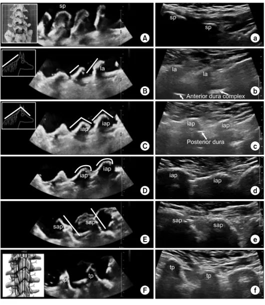
Fig. 8. Long-axis US images of the phantom’s (A-F) and corre- sponding real person’s (a-f) lum- bar vertebra with 5-1 MHz curved (A-F) and 18-4 MHz linear (a-f) transducer from spinous process to transverse process (From A to F indicating on the schematic picture in (F)). We made phantom with commercially available lumbar ver- tebra model and the water base that is shown in (A). All images are cephalad in left and caudad in right. sp, spinous process; la, lami- na; iap, inferior articular process;
sap, superior articular process; tp, transverse process.
(validity)가 높은 실행 가능한(feasible) 유도시술로 많이 보 고하였다.21-25
Interlaminar approach의 경우 맹검(blind technique)으로 시술할 때처럼 요추 3∼4번이나 요추 4∼5번 척추판 사이 공간으로 접근하며 중앙에서 여러 레벨의 요추 극돌기와 천추를 확인하고(Fig. 8A, a) 조금씩 외측으로 움직이면, 고 에코의 골조직이 깊은 곳에서 보이는데 말의 갈기가 붙어 있는 뒷목처럼 생긴 선이 보이며(Fig. 8B, b) 점차 외측으로 이동할수록 말의 얼굴 같이 보이는 앞부분의 고에코 음영 과 이어지는데(Fig. 8C, c) 이 말의 뒷목 같은 음영이 척추 판이고26 얼굴 같은 음영이 척추판에서 아래관절돌기 (inferior articular process)로 이행되는 부분이다. 초음파 유 도 시술을 위해 말의 뒷목 같은 고에코 음영만 보이는 부분 에 탐촉자를 고정하고 보면 척추판 사이 공간에서 말의 뒷 목 고에코 음영이 시작되는 깊이에서 탐촉자에 수평으로
보이는 구조가 뒤쪽의 경막(posterior dura)이며(Fig. 8C, c) 이 위를 저에코 또는 무에코의 황인대(ligamentum flavum) 가 덮고 있어 이 황인대까지 꼬리에서 머리 방향으로 (cephalad direction) 22 G Touhy needle을 진행시키고 황인 대에 바늘이 꽂혀 저항이 느껴지면 바늘에 공기나 생리식 염수가 들어 있는 주사기를 연결하여 플런저에 간헐적으로 압력을 주어 저항이 소실될 때까지 바늘을 조금씩 전진시 켜(loss-of-resistance technique)7,24 바늘 끝이 뒤쪽 경막외 공간에 위치하였다는 것을 확인하고 주사한다. 황인대까지 접근하고 주사기를 연결한 이후에는 탐촉자를 떼거나 (blind technique) 또는 탐촉자를 보조자가 잡고 시술자가 바늘과 주사기를 한 손씩 잡아서 안정적으로 시술하는 것 을 추천한다.
Pararadicular approach는 방사선 투시로 시행하는 선택 적 경추간공 경막외 신경차단술(selective transforaminal
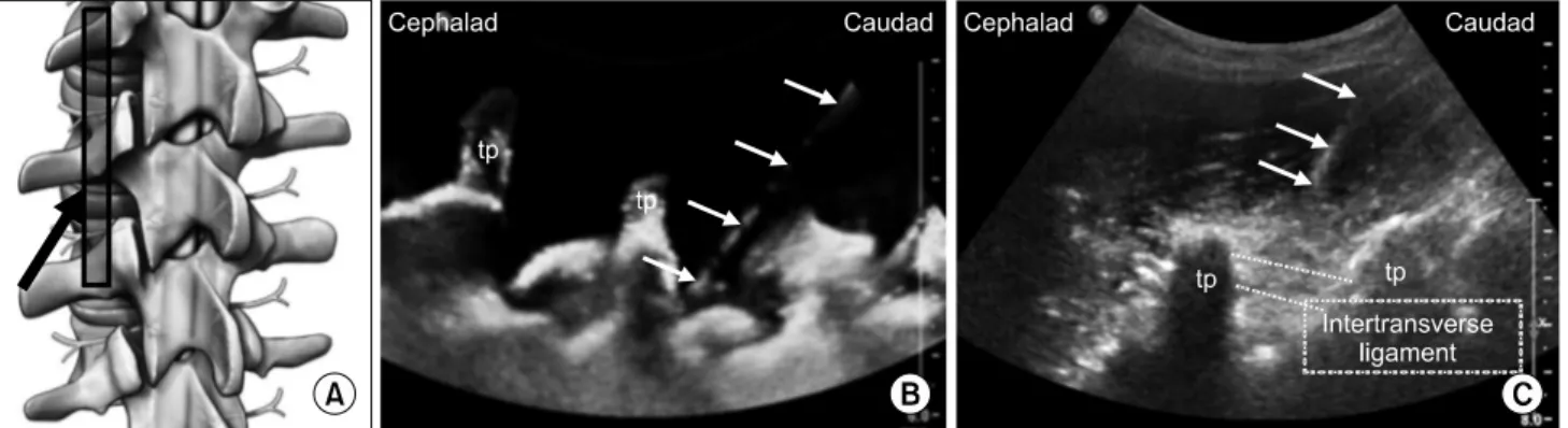
Fig. 9. Pararadicular epidural injection. Schematic picture (A) for needle direction (black arrow) and transducer position and long-axis US images of phantom (B) and real person (C) with 5-1 MHz curved transducer. Needle (white arrows) passes intertransverse ligament (structure between two dotted lines in C) into the transforaminal area. tp, transverse process.
epidural block, STE block)의 목표지점인 소위 ‘safe tri- angle’로 초음파를 이용해서 가이드해 주사하며 inter- laminar approach보다 외측에서 시행하게 된다. 척추에 대 하여 단축 영상22,23,25 또는 장축 영상8,21,24,25을 이용한 초음 파 유도 시술이 모두 보고가 되었는데 여기서는 장축 영상 을 이용한 접근법만 다루고자 한다. 위에서 기술한 척추판 과 아래관절돌기 부위에서 점차 외측으로 이동하면 각이 져 있던 말의 목과 얼굴 부분이 둥글어지며(Fig. 8D, d), 척 추후관절을 이루는 아래관절돌기의 최외측 부분이 관찰된 다. 더 외측으로 가면 꼬리방향으로 오름 경사 골구조가 없 어지며 이번에는 꼬리방향으로 내리막 경사 골구조가 나타 나는데(Fig. 8E, e) 이것이 아래 척추뼈의 윗관절돌기(superior articular process)이며 이 오름 경사 골구조와 내리막 경사 골구조 변환부위가 척추후관절이다. 더 외측으로 진행하면 윗관절돌기 음영이 없어지며 횡돌기의 기저부 음영이 나타 난다(Fig. 8F, f). 계속 외측으로 탐촉자를 이동하면 횡돌기 음영의 두께가 점차 얇아지다가 횡돌기의 끝(tip of trans- verse process)를 지나면 고에코의 음영이 사라진다. Para- radicular approach를 위한 주사바늘 삽입을 위해 윗관절돌 기 음영이 사라지며 횡돌기 기저부 음영이 보이기 시작하 는 위치에 탐촉자를 고정시키는데 이 때 최대한 횡돌기 기 저부의 내측이 보이도록 탐촉자를 외측으로 약간 기울인다 (paramedian oblique sagittal scanning). 22 G spinal needle 을 탐촉자의 원위부에서 삽입하고 꼬리에서 머리 방향으로 진행하여 횡돌기 음영의 중간 깊이 정도에서 탐촉자에 수 평으로 보이는 고에코 구조물인 횡돌기사이 인대(inter- transverse ligament)를 뚫고 주사하는데(Fig. 9B, C) 이 인 대의 전방으로 신경근이 지나기 때문이다. 2015년 Kim 등8 은 90명을 대상으로 paramedian approach로 초음파 유도 중재시술을 한 후 방사선 투시 검사로 확인하였는데 92.2%
(n=83)에서 조영제가 목표부위(targeted pararadicular com-
partment)로 주입되었고 4명의 환자에서 혈관 내 주사가 관 찰 되었지만 기타 심각한 합병증은 없었다고 보고하였다.
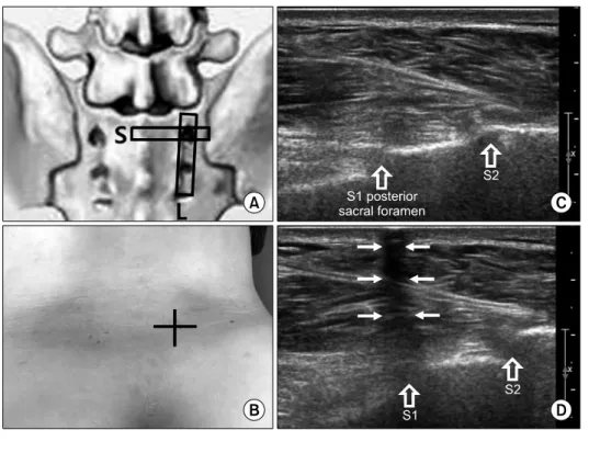
요추 5번 신경근이 지나는 요추 5번과 천추 1번 사이의 경 추간공은 골반골(pelvic bone)이 주사바늘이 지나가는 경로 를 막아 장축으로 접근은 불가능하여 단축 영상을 이용한 유도를 하든지 또는 2009년 Sato 등27이 보고한 것처럼 장 축 영상으로 요추 5번 신경근을 확인한 후 out of plane으로 바늘을 접근하여 요추 5번 신경근을 목표로 주사할 수도 있다. 천추 1번 신경근의 경우 첫 번째 전천추공(anterior sacral foramen)을 통해 빠져 나가고 전천추공은 후천추공 (posterior sacral foramen)과 통해 있기 때문에 초음파 유도 하 중재시술은 천추의 후천추공 안으로의 바늘 삽입이 목 표가 된다. 장축이나 단축 영상으로 첫 번째 후천추공을 어 렵지 않게 찾을 수 있으나 in plane으로 주사할 경우 후천추 공에서 다소 떨어진 내측(medial to lateral approach) 또는 꼬리쪽(caudal to cephalic or caudolateral to cephalomedial approach) 피부를 천자해서 접근해야 하는데 이 경우 후천 추공의 골조직에 걸려 신경근이 있는 더 깊숙한 공간으로 의 접근이 불가하다. 따라서 초음파 영상에 클립을 이용하 여 장축과 단축 영상 모두에서 후천추공의 직상방 피부의 위치를 파악해서 표시하고(Fig. 10) 맹검으로 바늘을 수직 으로 삽입해서 주사하거나 또는 Sato 등28의 보고처럼 천추 에 대한 장축 영상에 out of plane으로 주사를 삽입하는 유 도시술이 추천되며, 후천추공이 외측에서 내측으로 비스듬 히 뚫려 있기 때문에 탐촉자를 수직으로 유지하고 바늘을 탐촉자의 외측에서 내측을 향하게 비스듬히 삽입한다. 맹 검이나 out of plane으로 접근하면 바늘 끝이 보이지 않기 때 문에 전기자극(electrical stimulation)으로 바늘의 위치를 조 정해 가며 신경을 찾아서 주사하면 정확도를 높일 수 있다.
Fig. 10. S1 nerve root injection.
(A) Schematic picture shows long- axis (L) and short-axis (S) trans- ducer position for finding posterior sacral foramina. (B) Marking for blind approach to S1 posterior sa- cral foramen to block the S1 nerve root. Long-axis 12-5 MHz US im- ages before (C) and after (D) clip application to find the S1 posterior sacral foramen showing acoustic shadowing (arrows) after clip ap- plication in (D).
결 론
이상과 같이 다양한 초음파 유도 중재시술이 요추에서도 가능하며 중재시술의 효과를 높이기 위해서는 요추부의 초 음파 해부학(sonoanatomy)을 정확히 파악하고 있어야 하고 요추부에 호발하는 질환에 대한 정확한 진단이 선행되어야 한다. 요통과 하지 방사통의 많은 부분을 차지하는 요추의 퇴행성 질환을 이해하고 영상 소견을 통해 구별할 수 있으 며 정확한 병변의 위치를 확인한 후 초음파를 이용한 중재 시술까지 이어지기 위해서는 병력 청취, 이학적 검사와 더 불어 영상 검사, 근전도와 같은 기능검사를 적극적으로 시 행해야 하겠다. 최근 초음파를 이용한 요추부의 중재시술 은 초음파 기술의 발전, 의사들의 많은 임상경험과 더불어 빠르게 발전하고 있다.
재활의학 영역에서도 단순한 요통 환자뿐 아니라 재활치 료를 시행 중인 다양한 환자군에서 동반된 요통 환자들을 위해서도, 외래에서 비교적 빠르고 간단하게 시행할 수 있 는 초음파 유도 중재시술이 점차 확대되고 보편화되길 기 대한다.
REFERENCES
1. Resnick D, Kransforf M. Bone and joint imaging, 3rd ed.
Philadelphia: Elsevier-Sauders 2005; 394-424
2. Gallucci M, Puglielli E, Splendiani A, Pistoia F, Spacca G.
Degenerative disorders of the spine. Eur Radiol 2005;
15(3): 591-598
3. Resnick D. Degenerative diseases of the vertebral column, Radiology 1985; 156: 3-14
4. Chi M, Chen AS. Ultrasound for Lumbar Spinal Procedures. Phys Med Rehabil Clin N Am 2018; 29: 49-60 5. Gofeld M, Bristow SJ, Chiu S. Ultrasound-guided injection
of lumbar zygapophyseal joints: an anatomic study with fluoroscopy validation. Reg Anesth Pain Med 2012; 37(2):
228-231
6. Greher M, Kirchmair L, Enna B, Kovacs P, Gustorff B, Kapral S, Moriggl B. Ultrasound-guided lumbar facet nerve block: accuracy of a new technique confirmed by computed tomography. Anesthesiology 2004; 101(5): 1195-1200 7. Karmakar MK, Li X, Ho AM, Kwok WH, Chui PT.
Real-time ultrasound-guided paramedian epidural access:
evaluation of a novel in-plane technique. Br J Anaesth 2009; 102(6): 845-854
8. Kim YH, Park HJ, Moon DE Ultrasound-guided Pararadicular Injection in the Lumbar Spine: A Comparative Study of the Paramedian Sagittal and Paramedian Sagittal Oblique Approaches. Pain Pract 2015;
15(8): 693-700
9. Nizard RS, Wybier M, Laredo JD. Radiologic assessment of lumbar intervertebral instability and degenerative spondylolisthesis. Radiol Clin North Am 2001; 39(1):
55-71
10. Devereaux MW. Anatomy and examination of the spine.
Neurol Clin 2007; 25(2): 331-351
11. Fagan A, Moore R, Vernon Roberts B, Blumbergs P, Fraser R. ISSLS prize winner: The innervation of the interverte- bral disc: a quantitative analysis. Spine 2003; 28(23):
2570-2576
12. Malfair D, Beall DP. Imaging the degenerative diseases of the lumbar spine. Magn Reson Imaging Clin N Am 2007;
15(2): 221-238
13. Pfirrmann CW, Metzdorf A, Zanetti M, Hodler J, Boos N.
Magnetic resonance classification of lumbar intervertebral disc degeneration. Spine 2001; 26(17): 1873-1878 14. Costello RF, Beall DP. Nomenclature and standard report-
ing terminology of intervertebral disk herniation. Magn Reson Imaging Clin N Am 2007; 15(2): 167-174 15. Lee GY, Lee JW, Choi HS, Oh KJ, Kang HS. A new grad-
ing system of lumbar central canal stenosis on MRI: an easy and reliable method. Skeletal Radiol 2011; 40(8):
1033-1039
16. Lee S, Lee JW, Yeom JS, Kim KJ, Kim HJ, Chung SK, Kang HS. A practical MRI grading system for lumbar fora- minal stenosis. AJR Am J Roentgenol 2010; 194(4):
1095-1098
17. Cohen SP, Raja SN. Pathogenesis, diagnosis, and treatment of lumbar zygapophysial (facet) joint pain. Anesthesiology 2007; 106(3): 591-614
18. Han SH, Park KD, Cho KR, Park Y. Ultrasound versus flu- oroscopy-guided medial branch block for the treatment of lower lumbar facet joint pain: A retrospective comparative study. Medicine (Baltimore) 2017; 96(16): 1-7
19. Parr AT, Manchikanti L, Hameed H, Conn A, Manchikanti KN, Benyamin RM, Diwan S, Singh V, Abdi S. Caudal epidural injections in the management of chronic low back pain: a systematic appraisal of the literature. Pain Physician
2012; 15(3): 159-198
20. Fukazawa K, Matsuki Y, Ueno H, Hosokawa T, Hirose M.
Risk factors related to accidental intravascular injection during caudal anesthesia. J Anesth 2014; 28(6): 940-943 21. Loizides A, Gruber H, Peer S, Galiano K, Bale R,
Obernauer J. Ultrasound guided versus CT-controlled para- radicular injections in the lumbar spine: a prospective randomized clinical trial. AJNR Am J Neuroradiol 2013;
34(2): 466-470
22. Wan Q, Wu S, Li X, Lin C, Ke S, Liu C, Xin W, Ma C.
Ultrasonography-Guided Lumbar Periradicular Injections for Unilateral Radicular Pain. Biomed Res Int 2017; 2017:
8784149
23. Yang G, Liu J, Ma L, Cai Z, Meng C, Qi S, Zhou H.
Ultrasound-guided Versus Fluoroscopy-controlled Lumbar Transforaminal Epidural Injections: A Prospective Randomized Clinical Trial. Clin J Pain 2016; 32(2):
103-108
24. Hurdle MF. Ultrasound-Guided Spinal Procedures for Pain:
A Review. Phys Med Rehabil Clin N Am 2016; 27(3):
673-686
25. Gofeld M, Bristow SJ, Chiu SC, McQueen CK, Bollag L.
Ultrasound-guided lumbar transforaminal injections: feasi- bility and validation study. Spine 2012; 37(9): 808-812 26. Karmakar MK, Li X, Kwok WH, Ho AM, Ngan Kee WD.
Sonoanatomy relevant for ultrasound-guided central neu- raxial blocks via the paramedian approach in the lumbar region. Br J Radiol 2012; 85(1015): e262-e269
27. Sato M, Simizu S, Kadota R, Takahasi H. Ultrasound and nerve stimulation-guided L5 nerve root block. Spine (Phila Pa 1976) 2009; 34(24): 2669-2673
28. Sato M, Mikawa Y, Matuda A. Ultrasound and electrical nerve stimulation-guided S1 nerve root block. J Anesth 2013; 27(5): 775-777