헬리컬 기어계의 가진원 성능 평가에 대한 실험적 연구
Experimental Study on Performance Tests of Vibration Source for Helical
Gears
박광민
†․ 김찬중* ․ 이재원* ․ 이봉현*․ 김완수**
Gwang-Min Park, Chan-Jung Kim, Jae-won Lee, Bong-Hyun Lee, Wan-soo Kim
Key Words : Helical Gear(헬리컬기어), Transmission Error(전달오차), Gear Mesh Frequency(기어 물림 주파
수), Vibration(진동), Gear Wine Noise(기어 와인 소음)
ABSTRACT
A gearbox can be regarded as a self-exciting dynamic system, which has a vibration source. Transmission error (TE) is considered to be an main excitation source for gear noise and vibration. The TE excitation is transmitted through the gears, shafts, bearings, and housings. Thus, an ex-perimental approach to each mechanical parts is useful in order to understand and evaluate the dy-namic behaviour of a gearbox. This study is focused on the transmission and vibration characteristics of a helical gear system in development stage. In addition, by considering the tolerance factors and resonance characteristics, the vibration response of actual dynamic system is analysed.
1. 서 론1) 종래의 기어장치는 대부분 동력전달과 감가속 등 의 기본 목적을 위해 적용된 반면, 최근에는 저소음, 저진동을 유지하면서 원활한 운동 전달이 가능한 고 급품질의 기어가 요구되고 있다. 본 연구에서는 대 표적인 기어 장치인 헬리컬 기어를 대상으로 기어구 동계를 설계·제작하여 가진원 평가를 위한 시험적 프로세스 개발을 목표로 하고 있으며, 특히 진동원 이 되는 제작요인, 공진특성 등을 고려하여 실제 시 스템의 동적 응답 특성을 측정 및 분석하였다. 2. 가진원 성능 평가 2.1 제작/조립 오차 측정 기어 진동은 크게 제조/조립요인, 각 기계부품의 † 교신저자 ; 정회원, 자동차부품연구원 대구경북본부 E-mail : [email protected] Tel : 053-592-8977, Fax : 053-592-3169 * 자동차부품연구원 ** 현대기아자동차
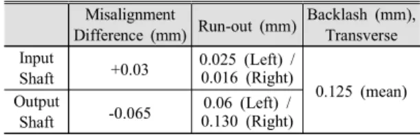
Table 1 Measurement Data
Misalignment Difference (mm) Run-out (mm) Backlash (mm), Transverse Input Shaft +0.03 0.025 (Left) / 0.016 (Right) 0.125 (mean) Output Shaft -0.065 0.06 (Left) / 0.130 (Right)
Table 2 Natural Frequency Characteristics
Parts Natural Frequency [Hz]
1st 2nd
Test Rig (Left) 1,499 3,048 Test Rig (Right) 1,076 1,861 Input Bearing 282 795 Output Bearing 222 -공진 등에 의하여 발생된다. 치형 오차 이외에도 축 정렬 오차 등의 조립요인은 치의 맞물림 충격과 치 면 응력집중 현상을 야기한다. Table 1은 제작된 헬 리컬 기어셋의 주요 제작/조립 오차를 나타낸다. 2.2 공진특성 평가 기어계의 작동 영역 내의 로컬 공진점은 시스템 한국소음진동공학회 2014년 추계학술대회 602
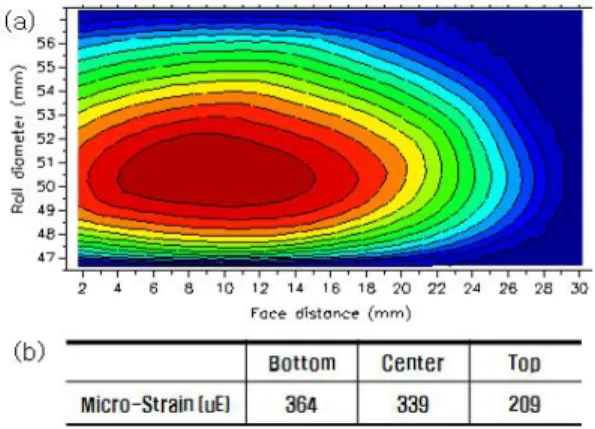
Fig. 1 Tooth Contact Stress Pattern (a) Simulation
Result (b) Root Strain (Experiment)
의 진동 응답 특성에 영향을 준다. Table 2는 본 연 구에서 구축한 헬리컬 기어계의 작동 주파수 내에 공진 특성을 가지고 있는 주요 기계요소에 대한 고 유진동수를 측정한 결과를 나타낸다. 2.3 접촉 응력 분포 해석/시험 Fig 1은 기어 접촉응력 분포의 시뮬레이션 결과 와 실제 치저부 스트레인 측정 결과를 나타낸다. 시 스템의 제작/조립 오차 측정결과에서 예상할 수 있 듯이 치면의 Bottom Lead 쪽에 응력이 집중되었다. 2.4 전달오차 성능 시험 기어의 회전방향 진동 전달 특성을 평가하기 위 하여 입력축과 출력축에 로터리 엔코더를 장착하여 정적 전달오차와 동적 전달오차를 각각 측정하였다. Table 3은 저속영역에서 부하별로 Peak-Peak TE (PPTE)를 측정한 결과를 나타낸다. 본 대상품의 치 형 특성은 저토크 영역보다 약 60Nm 토크 영역에 서 진동 특성이 개선된 모델인 것으로 분석된다.
Table 3 Peak-Peak TE results (at 60 rpm)
Load cases 30 Nm 60 Nm 90 Nm PPTE (average, um) 12.33 11.92 14.55
Fig. 2 Dynamic Transmission Error Trace
Fig 2는 입력축 회전수에 따른 동적 전달오차의 크 기를 분석한 결과이다. 구동속도에 따라 비교적 선 형적으로 증가하지만 750rpm 부근에서 진폭이 커지 며, 이는 출력축 베어링의 고유진동수와 기어의 물 림주파수가 중첩되어 나타나는 현상으로 사료된다. 2.5 진동 시험 Fig 3은 베어링부 마운팅을 위한 테스트 리그의 진동 측정 데이터에 대한 Waterfall 분석결과를 도 시한 것이다. 220Hz 부근의 베어링 공진과 1,075Hz 부근의 테스트 리그 등에 의한 로컬 공진점에 의하 여 진동의 크기가 증가함을 확인할 수 있다.
Fig. 3 Waterfall Analysis (Color Map)
3. 결 론 본 연구에서는 헬리컬 기어계의 진동 전달 특성 을 분석하기 위해 기존의 기어 치형 오차 분석 관점 이 아닌 조립오차, 구조적 공진 등의 관점에서 가진 원을 평가하는 실험적 프로세스를 제시하였다. 또한 시험 결과를 통해 대상 기어계의 구조적 진동 요인 을 거시적인 관점에서 파악할 수 있었다. 본 시험 평가 방법을 활용하여 치형 수정 전 단계에서 제작 오차, 구성부품의 공진점 분석을 통해 가진원의 전 달 특성을 평가하고 진동성능을 개선하기 위해 필요 한 기초자료로 활용할 수 있을 것으로 기대한다. 후 기 본 연구는 산업통상자원부에서 시행중인 산업융 합원천기술개발사업(FF형 PHEV를 위한 150kW 급 멀티모드 변속시스템을 적용한 동력전달장치 개 발, 10040083)의 지원하에 수행되었습니다. 603