A Study on the Noise and Vibration Analysis of 200kW PMSM for
Electric Propulsion Ship
Yang-Uk Cho *, and Gyu-Hong Kang *
Abstract
– This paper presents one of the methods for design to reduce the noise and vibration of 200kW motor for electric propulsion ship. One of the important factors affecting vibration of the motor is the resonance. The natural frequency and natural mode of the 200kW motor is analyzed by using FEM tool and impact test equipment to avoid the resonance. Also, compare FEM result with impact test result to make a reliable FE model of 200kW motor. In order to find out the effect of the noise and vibration of the motor by electromagnetic excitation force, conduct electromagnetic-structure coupled analysis. These characteristics are much useful to design 200kW motor for electric propulsion shipKeywords:
Natural frequency, Natural mode, Resonance, Tangential force, Radial force, Structural vibration, Electromagnetic force, Radiated noise, Boundary element method1. Introduction
The Study of the electric motor has been conducted due to CO2 emission regulation policy and its increasing trend
capacity. However, the increasing noise and vibration problem is occurred according to increasing the electric motor capacity. Focus on design of the increasing electrical characteristics of the motor for high output, the noise and vibration that occurs will affect the system. To reduce the vibration and noise, it needs to analyze the characteristics of the motor causing the noise and vibration.
The basic function of the motor is converting electrical energy into mechanical energy. In the process of converting energy, the electromagnetic force is generated. The radial electromagnetic force is the greatest effect on the noise and vibration of the motor during operation [1]-[2]. Particularly the more noise and vibration will occur when the rotation frequency of the electric motor leads to the resonance. William was analyzed by dividing the electrical part and mechanical part of noise and vibration source, and dealing with resonance, critical speed, and rotating unbalance [3]-[5]. The vibration caused motor noises can be reduced by changing of design avoiding the resonance and electromagnetic forces that occur in the motor operating condition. Thus, the vibration characteristic and the natural frequency analysis of the motor are very important.
In this paper, 200kW motor for electric propulsion ship
was analyzed to design the low vibration motor. Finite element method (FEM) analysis and impact test was carried out to find the natural frequency and the natural mode. And compare FEM analysis result with impact test result to obtain a reliable FE model of the 200kW motor. On the basis of the validated FE model, electromagnetic-structure coupled analysis was carried out in order to see effect on the vibration of the motor by electromagnetic force. The low vibration motor will be designed by comparing the experimental result with numerical results. And the vibration characteristics of 200kW motor will be based testing on the improvements.
2. Natural Frequency Analysis
Analysis model of the 200kW motor for electric propulsion ship is shown in Fig. 1 and the specifications are shown in Table 1. FE model mesh shown in Fig. 1 used 3D solid element composed of 160,901 hexa elements and 1,854 penta elements.
Fig. 1. 3D and FE model of 200kW motor * Electric & Electronic Research Division, Korea Marine Equipment
Research Institute, Korea. ([email protected])
Table 1. Specifications of the 200kW motor ITEM Specification Rated Speed [rpm] 3500 Rated Torque [Nm] 555.28 Rated Current [Arms] 255 Poles / Slots 16 / 18 Air-gap length [mm] 2 Stator diameter [mm] 220
FEM analysis and impact test were performed to analyze the natural frequency and the natural mode. And FE model of 200kW motor parts was verified by comparison FEM analysis with impact test result. Commercial program Nastran was used for modal analysis and LMS Test. Lab was used for impact test. FE model is shown in Fig. 1 and impact test equipment is shown in Fig. 2.
Impact test equipment was composed with LMS Test.Lab, accelerometer and impact hammer. And impact test data acquisition setting was shown in Table 2. The sampling frequency was set at 3200 Hz since excitation frequency of the impact hammer is 3200Hz. And use window function in order to reduce leakage error.
Fig. 2. Impact test equipment Table 2. Impact test data acquisition setting
ITEM Specification
Sampling frequency [Hz] 3200
Resolution [Hz] 0.7592
Record length [s] 1.317
Averaging 3 times
Window function Input – Force exponential/ Output – Exponential Impact test was performed about 200kW motor parts on the sponge to make condition of free DOF.
Impact test geometry of the front cover, one of the 200kW motor parts, was shown in Fig. 3 and composed of the 56 nodes. Impact test was carried out about 56 nodes and 3 times average per one node.
FRF (Frequency response function) was shown in Fig. 6 at self-excitation point on the front cover. And natural mode was shown in combination with the natural vector of each node. Fig. 4 shows natural mode shape of the front cover. There are bending mode at first mode (443 Hz) and
second mode (767 Hz).
Also, the modal analysis was performed using FEM tool. The result was shown in Fig. 5. It was confirmed that the same mode shape of the impact test result and FEM analysis result. FE model of the 200kW motor was verified by comparison with impact test result.
Fig. 6 shows the FRF at self-excitation point on the front cover. It can be seen that impact test result and FEM analysis result are relatively well matched.
Fig. 3. Impact test geometry of the front cover
Fig. 4. First and second natural mode shape by impact test
Fig. 5. First and second natural mode shape by FEM
Fig. 6. FE model of the 200kW motor and front cover Even more impact test and FEM analysis was performed
0 500 1000 1500 2000 2500 3000 10-2 100 102 104 106 108 Frequency(Hz) Ampli tude(Acceleration, m/s 2 ) Impact test FEM analysis
about other motor parts and the first and second natural frequency was shown in Table 3. It seems that the result of the impact test and FEM analysis was almost coincided. Table 3. Natural frequency of the 200kW motor
ITEM Experiment(Hz) FEM Analysis(Hz) 1st mode 2nd mode 1st mode 2nd mode Front cover 443 767 436 772 Housing 390 537 369 513 Rear cover 356 416 354 420 Shaft 1208 2829 1211 2824
3. Electromagnetic Analysis
The electromagnetic characteristic of the 200kW motor was applied to a finite element analysis in this study. Changing of the air-gap flux density was investigated to effect vibration of the motor by electromagnetic force.
Fig. 7 shows magnetic flux density distribution and magnetic flux line about 1/2 model of 16 poles and 18 slots. Segmentation of permanent magnetic, shape of a magnetic circuit and combination of the pole and slot were optimized through design of experiment to minimize cogging torque and torque ripple.
Fig. 7. Magnetic flux density and magnetic flux line
Fig. 8. Electromagnetic force distribution according to time and distance
Fig. 8 shows that electromagnetic force according to time and distance of teeth. Unbalanced magnetic forces acting on the rotor surface was calculated with the Maxwell stress tensor and the radial and tangential force is (1) and (2) [6].
t)] , (θ B t) , (θ [B 2μ 1 t) , (θ F s 2 θ s 2 r 0 s rad (1) t)] , (θ B t) , (θ [B μ 1 t) , (θ F r s θ s 0 s tan (2)
where, Frad is radial component of force density, and Ftan is
tangential component. Br and Bθ are the radial and
tangential component of the air-gap flux density. μ0 is
magnetic permeability at free space. θs is angular position
and t is time. It was assumed that electromagnetic force between rotor surface and teeth will occur through action and reaction at air gap. Input source of structure analysis is calculated the sum of the electromagnetic force every step.
Fig. 9 shows the radial and tangential force in frequency domain. Looking in the frequency domain, there is a frequency of the electromagnetic force (933 Hz) in both radial and tangential force.
Fig. 9. Frequency domain of the radial and tangential force
4. Structure Vibration Analysis
Frequency response analysis was carried out using electromagnetic force calculated by electromagnetic analysis. It was assumed that the electromagnetic force is acting on the teeth surface. So, structural excitation force was applied to the nodes of teeth surface.
0 500 1000 1500 2000 2500 3000 3500 4000 4500 5000 10-2 100 102 104 Frequency(Hz) A mpl itude (Radi al Fo rc e, N ) 0 500 1000 1500 2000 2500 3000 10-4 10-2 100 102 Frequency(Hz) A m p li tu d e (T a n g e n ti a l F o rc e , N )
Frequency response at a node of housing surface was shown in Fig. 10. The frequency of electromagnetic force and the multiple component of the rotating frequency appear significantly.
Fig. 10. The caption for a figure must follow the figure The RMS (Root mean square) value of the vibration at the housing is 2.10 um and peak to peak value is 91.7 um.
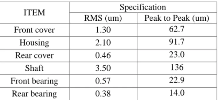
To compare the magnitude of the motor vibration generated by electromagnetic force, the magnitude of the frequency response at the nodes of the motor surface was shown in Table 4.
Table 4. Magnitude of the vibration at the motor surface
ITEM Specification
RMS (um) Peak to Peak (um)
Front cover 1.30 62.7 Housing 2.10 91.7 Rear cover 0.46 23.0 Shaft 3.50 136 Front bearing 0.57 22.9 Rear bearing 0.38 14.0
It can be seen that the more vibration occur at shaft, the next is housing. The motor vibration occur entirely front part of the motor more than rear part of the motor.
5. Radiated Noise Analysis
The radiated noise analysis of the 200kW motor is conducted by boundary element method. The results of the structure vibration by electromagnetic force are given as a boundary condition. Boundary element model was composed of outer surface of the motor, base plane and field point. Symmetry plane was modeled for reflection of bottom and field point was modeled as shown in Fig. 11 according to ISO 3744.
The radiated noise distribution by electromagnetic force was shown in Fig. 12. Looking at the sound pressure
distribution in field point, it can be seen that it has occurred up to 86.1 dB(A).
Fig. 13 shows that 1/3 octave band of sound pressure level at the field point. The sound pressure level was generally higher in the high-frequency band and 1000 Hz band was confirmed to appear high. The electromagnetic force (933 Hz) is the main component in the 1000 Hz band.
Fig. 11. Field point mesh according to ISO 3744
Fig. 12. Sound pressure distribution over the field point mesh
Fig. 13. 1/3 Octave band of sound pressure level
6. Conclusion
In this paper, the method for design to reduce the noise and vibration of the 200kW motor for electric propulsion ship was presented by FEM analysis and impact test. Also structural vibration analysis was carried out to see the effect
0 500 1000 1500 2000 2500 3000 3500 4000 4500 5000 10-8 10-6 10-4 10-2 100 Frequency(Hz) A mpl itude (D is pl ac e me nt, mm)
of the noise and vibration of the motor by electromagnetic excitation force.
To find out the resonance of the motor, the FEM analysis and impact test was performed. A reliable FE model was obtained by comparison the FEM analysis result and the impact test result. Analysis of whether or not the resonance with the electromagnetic excitation force was performed. The problem by the resonance was not detected.
The radial and tangential force acting on the teeth was calculated by electromagnetic analysis. The 933 Hz component of the radial and tangential force appears. Looking at the structural vibration analysis, there is a 933 Hz component, too. Compared to the magnitude of the vibration of the motor for each part, the most significant vibration occurred in the shaft and the more vibration occurs in front parts than rear parts. Thus, it is recommended to adjust the stiffness of the front part of the motor.
In the radiated noise analysis, 1000 Hz band component appear high. The electromagnetic force (933 Hz) is the main component in the 1000 Hz band. In order to reduce the noise and vibration of the motor should be reduced 933 Hz component which is frequency of the electromagnetic excitation force.
The analysis of 200kw motor vibration and radiated noise by electromagnetic excitation force was approached numerically, but it needs to be verified experimentally.
Acknowledgements
This work was supported by SW Convergence Components and Materials Technology Development (11043799) funded by Ministry of Trade, industry & Energy.
References
[1] W. H. Kim, I. H. Hong and J. T. Chung, “A study on noise reduction for the driving system of a forklift,” Transactions
of the Korean society for noise and vibration, vol. 18, no. 1,
pp.80-86, 2008.
[2] H. J. Lee, J. H. Kwon, C. M. Lee, G. Y. Hwang and S. M. Hwang, “Analysis of noise characteristics considering magnetic force of IPM motor,” KSNVE, vol. 19, no. 5, pp. 439-446.
[3] S. P. Verma and A. Balan, “Determination of radial force in relation to noise and vibration problems of squirrel-cage induction motors,” IEEE Transactions on Energy Conversion, vol. 9, no. 2, pp. 404-412, 1994.
[4] R. William, “An analytic approach to solving motor vibration problems” IEEE., vol. 36, pp. 1476-1480, 2000.
[5] D. G. Dorell, “Calculation of unbalanced magnetic pull in small cage induction motors with skewed rotors and dynamic rotor eccentricity,” IEEE Transaction of Energy Conversion, vol. 11, no. 3, pp. 483-488, 1996.
[6] J. F. Gieras, C. Wang and J. C. Laj, “Noise of Polyphase Electrical Motors,” Taylor & Francis Group, ISBN 01-8247-2381-3
Yang-Uk Cho received B.S degree in mechanical engineering from Pusan National University. He is researcher in Korea Marine Equipment Research Institute. His research interests are noise and vibration.
Gyu-Hong Kang received M.S and Ph.D. degree in electrical engineering from Changwon National University. He is general manager in Korea Marine Equipment Research Institute. His research interests are electrical machine and FEM analysis.