P2-29 / K. Hong
• IMID 2009 DIGEST
Abstract
Conventional depth extraction in integral imaging is based on the disparity information between the elemental images. Since the disparity is measured in pixel unit, however, the extracted depth is discrete, resulting in the quantization error. Moreover, the quantization error grows as the object depth increases, which limits the accuracy of the depth extraction for distant objects. In this paper, we propose a new method for depth extraction in integral imaging using pixel registration information between sub-images to obtain linear and accurate depth.
1. Introduction
Integral imaging is a well known three-dimensional (3D) display method which was firstly proposed by Lippmann in 1908 [1]. System configuration of integral imaging comprises a lens array and a two-dimensional (2D) display device on which an elemental image set is displayed. The elemental image set is integrated through the lens array to be perceived as a 3D image by observers. In the focused mode integral imaging system, the display panel is positioned at the focal length of the lens array [2].
Acquiring depth information of three-dimensional objects in the real world is an important issue in the three-dimensional display and computer vision. The depth information of object can be extracted from integral imaging system. In the integral imaging system, corresponding points of the object are located in the adjacent elemental images. The depth of object
can be extracted from the disparity of these corresponding points [3]. g l p 1 d d2 Lens2 Lens1
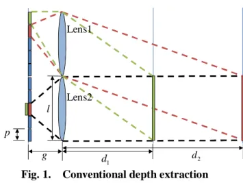
Fig. 1. Conventional depth extraction
In Fig. 1, conventional depth extraction method for the focused mode of integral imaging is shown. The depth can be extracted by using triangulation from the disparity between the center pixel of Lens 2 and its corresponding pixel in the elemental image of Lens 1. In this figure, the depth is given by
i
gl
d
pi
=
(1)where g is gap between elemental image plane and
Accurate depth extraction in 3D integral imaging using
sub-pixel registration information
Keehoon Hong*
1, Jisoo Hong
1, Jae-Hyeung Park
2and Byoungho Lee
11
School of Electrical Engineering, Seoul National University, Seoul 151-744, Korea Tel.:82-2-880-9570, E-mail: [email protected]
2
School of Electrical & Computer Engineering, Chungbuk National University, Cheongju-Si 361-763, Korea
P2-29 / K. Hong
IMID 2009 DIGEST • lens array, l is lens pitch, p is CCD pixel pitch
and i is the pixel-unit distance between corresponding pixel and the center of Lens 2. This conventional method has two major drawbacks. One is the discontinuity of the extracted depth due to the finite size of CCD pixels and the other one is that the extracted depth resolution becomes sparser for farther objects. The objective of this paper is to extract the depth with reduced discontinuity and uniform resolution using the sub-pixel registration information of sub-images. In the followings, the principle of the proposed method and its verification are presented.
2. Principle of proposed method
The inaccuracy of conventional depth extraction method originates from the limited precision of the disparity measurement in the elemental image set.
g l dis d obj d dcon reg d err d
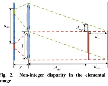
Fig. 2. Non-integer disparity in the elemental image
Figure 2 shows the depth extraction when the object is placed on the depth plane which has non-integer corresponding pixel disparity value in the elemental image. The true depth of the object is dobj, but the conventional method extracts depth
d
con with depth errord
err .Sub-image, which is also called directional image, is a collection of the pixels at the same position in every elemental image. The projection geometry of the sub-image is orthographic [4]. If we know the registration vector dreg between two sub-images; one from a set of lens’ center pixels and the other one
from a set of corresponding pixels, object depth
d
con, extracted by conventional method, can be corrected.Iterative intensity interpolation algorithm is used to find sub-pixel registration vectors between two sub images [5, 6]. The error of depth in the conventional method is calculated by using simple triangulation with registration information, and can be expressed by
tan
reg errd
d
θ
=
(2)where,
θ
is perspective angle difference between two sub images which is given byarctan
d
disl
g
θ
=
⎛
⎜
−
⎞
⎟
⎝
⎠
. (3)After the error of extracted depth from conventional method is obtained, the depth of object dobjcan be determined by
tan
obj con err reg con
d
d
d
d
d
θ
=
+
=
+
(4)3. Simulation results
In this simulation, lens array composed of 1 mm x 1 mm, 20(V) x 20(H) lenses are used for pick-up process in the integral imaging system. The gap between the lens array and CCD plane is 3 mm.
P2-29 / K. Hong
• IMID 2009 DIGEST
The elemental image sets are taken from a plane object at various depth planes ranging from 30 mm to 38 mm with an interval of 1 mm. Figure 3 shows the plane objects in the different depths which are used in the simulation.
In each depth, the depth extraction is performed by both conventional and proposed method. To find depth error of conventional method, sub-images are generated. Figure 4 shows the sub images of the planar object which is located at 35 mm. Figure 4(a) is the sub-image from the center pixels of elemental images and Fig. 4(b) is the sub-image from the corresponding pixels of the elemental images.
(a) (b)
Fig. 4. Sub-images (a) from center pixels, (b) from corresponding pixels
Using these sub-images, registration vectors are estimated with 0.001 pixel registration accuracy. In this simulation, ground truth of the x registration value is 0 because upper sub-image is selected as the second sub-image. The estimated registration vectors (x, y) between two sub-images are shown in Table 1.
TABLE 1. Registration vectors
Depth [mm] 30 31 32 33 34 Registration vector[mm] (-0.003, 0.297) (-0.002, 0.317) (-0.004, 0.388) (-0.003, -0.007) (-0.001, -0.006) Depth 35 36 37 38 Registration vector (-0.002, 0.030) (-0.002, 0.060) (-0.004, 0.117) (-0.004, 0.151)
Using the estimated registration vectors shown in Table 1, the accurate depths of the object can be calculated by Eq. (3).
Figures 5 and 6 compare two simulation results obtained from the conventional and the proposed depth extraction methods. In both graphs, ground-truth results are represented as a dotted line and simulation results as a solid line.
Fig. 5. Conventional result
Figure 5 shows extracted depth result of the conventional method. The conventional method extracts only two discontinuous depths, 23 mm and 35 mm, in the depth range 30 mm to 38 mm. The error of extracted depth is also significant compared to the ground-truth results.
Fig. 6. Proposed result
Figure 6 shows the result of the proposed depth extraction method. Compared to the conventional method shown in Fig. 5, the proposed method extracts the depth with much reduced errors with minimized discontinuity.
P2-29 / K. Hong
IMID 2009 DIGEST •
4. Summary
Accurate depth extraction in the integral imaging using sub-pixel registration information is proposed. Conventional depth extraction extracts discontinuous and erroneous depths due to the quantization error. But the proposed error correction algorithm can overcome this problem using sub-pixel difference information between sub-images in integral imaging. Simulation results show that the proposed depth extraction method provides continuous and accurate depth information compared to the conventional method.
Acknowledgment
This work was supported by the Brain Korea 21 Program (Information Technologies).
5. References
1. G. Lippmann, C. R. Acad. Sci. 46, p.446–451 (1908).
2. J. Park, Y. Kim, J. Kim, S. Min, and B. Lee, Opt.
Express. 12, p.6020-6032 (2004).
3. J.-H. Park, S. Jung, H.Choi, Y. Kim, and B. Lee,
Appl. Opt. 43, p.4882-4895 (2004).
4. B. Lee, J.-H. Park, and S.-W. Min, Digital Holography and Three-Dimensional Display, T.-C. Poon, eds. (Springer, New York, USA, 2006) Chapter 12.
5. P. Thévenaz, U.E. Ruttimann and M. Unser, IEEE
Transactions on Image Processing 7, p.27–41
(1998).
6. Q. Tian, M.N. Huhns, Comput. Vision Graphics