IEEE PHOTONICS TECHNOLOGY LETTERS, VOL. 33, NO. 1, JANUARY 1, 2021 23
112-Gb/s PAM4 Transmission Over 1 km of MMF
With Mode-Field Matched
Center-Launching in 850-nm Band
Minsik Kim , Byung Gon Kim , Member, IEEE, Sunghyun Bae , Member, IEEE,
and Yun C. Chung , Fellow, IEEE
Abstract— We evaluate possibility of utilizing the
mode-field matched center-launching (MCL) technique in the 850-nm band. For this purpose, we realize the MCL technique by fusion-splicing the HI-780 pigtail fiber of the transmitter to the OM2-type transmission multi-mode fiber (MMF). The results show that we can achieve the high coupling efficiency of >92% by optimizing the splicing conditions such as the arc-discharge duration and fiber-push distance. We confirm that, in the case of utilizing the MCL technique, the frequency-response characteristics of the MMF link becomes almost identical to that of the single-mode fiber (SMF) link. As a result, we could demonstrate the successful transmission of 112-Gb/s four-level pulse amplitude modulation (PAM4) signal operating at 852 nm over 1 km of the OM2-type MMF by utilizing the MCL technique. The performance of this link is measured to be very stable even in the presence of the mechanical perturbations such as fiber bending and fiber shaking.
Index Terms— Multi-mode fiber, pulse amplitude modulation,
mode-field matched center-launching technique.
I. INTRODUCTION
M
ULTI-MODE fiber (MMF) has been widely used in various short-reach applications such as the datacenter networks and local area networks [1]. Recently, the data rate required in these applications has been increased to>50 Gb/s/channel [2], [3]. However, it is difficult to transmit
such a high-speed signal through the MMF due to the modal dispersion. For example, it has been reported that, even in the case of utilizing the OM4-type MMF together with a decision-feedback equalizer (DFE), the transmission distance of the 107-Gb/s signal modulated in the four-level pulse amplitude modulation (PAM4) format is limited to be merely 105 m [4]. Previously, we have proposed the mode-field matched center-launching (MCL) technique to overcome the modal dispersion in the MMF link [5], [6]. In this technique, the mode-field matched center-launching condition is achieved simply by
Manuscript received October 8, 2020; revised November 4, 2020; accepted November 25, 2020. Date of publication December 1, 2020; date of current version December 11, 2020. This work was supported by the Institute for Information and Communication Technology Planning and Evaluation (IITP) Grant through the Korean Government under Grant 2017-0-00702. (Corresponding author: Yun C. Chung.)
The authors are with the School of Electrical Engineering, Korea Advanced Institute of Science and Technology (KAIST), Daejeon 34141, South Korea (e-mail: [email protected]; [email protected]; bsh88@kaist. ac.kr; [email protected]).
Color versions of one or more figures in this letter are available at https://doi.org/10.1109/LPT.2020.3041718.
Digital Object Identifier 10.1109/LPT.2020.3041718
fusion-splicing the pigtail single-mode fiber (SMF) of the transmitter to the transmission MMF. We have reported that, under this condition, it is possible to excite almost only the fundamental mode of the transmission MMF. For example, the coupling efficiencies (i.e., the ratio between the optical powers launched in the fundamental mode to the total modes in the MMF) achieved by the MCL technique are reported to be as high as∼95% in the 1.3- and 1.55-µm bands [5]–[7]. However, it is not clear if the MCL technique can still be used in the 850-nm band since the mode-field diameter of the SMF used in this band (i.e., HI-780 fiber) is much smaller than that of the standard SMF (i.e., SMF-28 fiber). For example, the mode-field diameters of the HI-780 and SMF-28 fibers are 5.0µm (@ 850 nm) and 9.2 µm (@ 1.3 µm), respectively. On the other hand, the mode-field diameter of the fundamental mode of the MMF is 11.6 µm at 850 nm and is 14.5 µm at 1.3 µm. Thus, the ratio between the mode-field diame-ters of the MMF and SMF is 2.32 at 850 nm, while it is only 1.58 at 1.3 µm. As a result, in the case of using the 850-nm band, it could be difficult to achieve the mode-field matched center-launching condition. Nevertheless, it would be highly desirable if we can utilize the MCL technique in the 850-nm band as well since it is the most commonly used wavelength band in the MMF links [2], [8].
In this letter, we evaluate the possibility of utilizing the MCL technique in the 850-nm band. The results show that we can still achieve a high coupling efficiency of >92% by utilizing the MCL technique (i.e., by fusion-splicing the HI-780 pigtail fiber of the optical transmitter to the legacy MMF under the optimum splicing conditions). We also confirm that, in the case of using the MCL technique, the frequency-response characteristics of the MMF link becomes almost identical to that of the SMF link. In addition, by utilizing the MCL technique, we demonstrate the transmis-sion of the 112-Gb/s PAM4 signal operating at 852 nm over 1 km of the OM2-type MMF. The performance of this link is measured to be very stable even when we shake the MMF by using a fiber shaker.
II. EXPERIMENT ANDRESULTS
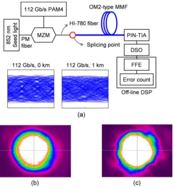
Figure 1(a) shows the experimental setup used to evalu-ate the performance of the MCL technique in the 850-nm band. In this experiment, we used a single-frequency laser diode operating at 852 nm (linewidth: 15 MHz) [9]. For
This work is licensed under a Creative Commons Attribution-NonCommercial-NoDerivatives 4.0 License. For more information, see https://creativecommons.org/licenses/by-nc-nd/4.0/
24 IEEE PHOTONICS TECHNOLOGY LETTERS, VOL. 33, NO. 1, JANUARY 1, 2021
Fig. 1. (a) Experimental setup to evaluate the performance of the MCL technique in the 850-nm band. The MCL technique was realized simply by fusion-splicing the HI-780 pigtail fiber of MZM to the OM2-type transmission MMF. The eye diagrams were measured in the back-to-back condition and the transmission over 1 km of the OM2-type MMF. (b) and (c) are the mode intensity profiles (obtained by using the MCL technique) measured in the back-to-back condition and after the transmission over 2.2 km of the OM2-type MMF, respectively.
the generation of the 112-Gb/s PAM4 signal, the output of this laser was directed to a LiNbO3Mach-Zehnder modulator
(MZM) having a 3-dB bandwidth of 25 GHz. Due to the use of the MZM, the null-to-null optical spectral width of this 112-Gb/s PAM4 signal was measured to be only ∼0.25 nm (indicating that it was limited by the information bandwidth). We fusion-spliced the HI-780 pigtail fiber of this MZM to the OM2-type MMF. The splicing conditions, such as the arc-discharge duration and fiber-push distance, were optimized to achieve the maximum coupling efficiency. We estimated the coupling efficiency by measuring the impulse response in a 2.2-km long OM2-type MMF [10], [11]. In this experiment, we utilized the MZM to demonstrate the capability of the MCL technique for the MMF transmission of the high-speed (>100 Gb/s) signal. However, in practice, we expect that an inexpensive SMF-pigtailed directly modulated laser (such as a vertical-cavity surface-emitting laser (VCSEL) or a distributed feedback (DFB) laser) could be used instead of the externally modulated transmitter [12]–[14]. We noted that, in this case, the system’s performance could be affected more by the chromatic dispersion than in the case of using the MZM due to the frequency chirp of the directly modulated laser.
The results in Fig. 2 showed that the maximum coupling efficiency of >92% was achieved when we set the arc-discharge duration and fiber-push distance to be 17 s and 19 µm, respectively. This efficiency of >92% was quite remarkable considering that the mode-field diameter of the HI-780 fiber (5.0 µm) was much smaller than that of the fundamental mode of MMF (11.6 µm) in the 850-nm band.
Fig. 2. Measured coupling efficiencies as functions of the arc-discharge duration and fiber-push distance.
Fig. 3. (a) Theoretically calculated frequency-response characteristics of the 500-m, 1-km, and 2-km long OM2-type MMF transmission links utilizing the MCL technique. (b) Measured frequency-response characteristics of the 1-km long OM2-type MMF link with and without utilizing the MCL technique in comparison with the calculated curve. The theoretically calculated curve in (b) is the same with the curve for 1-km long MMF in (a).
Due to this large coupling efficiency, the mode intensity profile was measured to be almost symmetrical and circular even after the transmission over 2.2-km long OM2-type MMF, as shown in Fig. 1(c).
We transmitted the 112-Gb/s PAM4 signal over the OM2-type MMF (either 500 m or 1 km), and then detected it by using an MMF-pigtailed receiver having a 3-dB bandwidth of 22 GHz. The MMF-pigtailed receiver was used (instead of the SMF-pigtailed receiver) to detect the PAM4 signal without the modal noises [6]. We sampled the detected signal at 80 Gsample/s by using a digital sampling oscilloscope (DSO), and applied a 9-tap feed-forward equalizer (FFE) to compensate for the signal distortions caused by the limited bandwidth and chromatic dispersion. The use of this FFE was indispensable since the end-to-end 3-dB bandwidth was mea-sured to be only∼13 GHz even in the back-to-back condition (due to the non-flat frequency-response characteristics of the modulator and receiver). As a result, the eye diagram of the 112-Gb/s PAM4 signal was measured to be completely closed even before the MMF transmission, as shown in the inset of Fig. 1(a).
We first evaluated the frequency-response characteristics of the OM2-type MMF link utilizing the MCL technique. Figure 3(a) shows the calculated frequency-response charac-teristics of 500-m, 1-km, and 2-km long MMF links achievable by using the MCL technique [15]. In these calculations, we assumed that the dispersion coefficient of the MMF was
KIM et al.: 112-Gb/s PAM4 TRANSMISSION OVER 1 km OF MMF WITH MODE-FIELD MCL 25
Fig. 4. Measured BER curves of the 112-Gb/s PAM4 signal in the back-to-back condition and after the transmission over 500 m and 1 km of the OM2-type MMF by using the MCL technique together with a 9-tap FFE.
−100 ps/km/nm in the 850-nm band [16] and neglected the modal dispersion (since the signal was carried mostly by the fundamental mode of the MMF when the MCL technique was utilized). In other words, we considered the MMF link utilizing the MCL technique as an SMF link. We also assumed that the laser output was intensity-modulated without chirp (i.e., by using an external modulator). The results showed that, even without considering the modal dispersion, the 3-dB bandwidth of the MMF link operating in the 850-nm band was reduced from 45 GHz to 32 GHz to 22 GHz when we increased its length from 500 m to 1 km to 2 km, respectively. The frequency notch observed at ∼32 GHz was caused by the RF power fading [15]. Thus, we concluded that it would be difficult to increase the transmission distance of the 112-Gb/s PAM4 signal to be much longer than 1 km in this OM2-type MMF link. Figure 3(b) shows the measured frequency-response characteristics of the 1-km long OM2-type MMF link (obtained with and without using the MCL technique) in comparison with the theoretically calculated curve (without considering the modal dispersion). When we utilized the MCL technique (i.e., the HI-780 pigtail fiber was fusion-spliced to the OM2-type MMF under the optimum conditions), the measured frequency-response characteristics of this MMF link agreed well with the calculated curve. This result indicated that, by using the MCL technique, we could utilize the MMF link as if it were an SMF link in the 850-nm band as well. In comparison, when we did not utilize the MCL technique (i.e., the HI-780 pigtail fiber was connected to the MMF by a fiber connector), the frequency-response characteristics of this MMF link was measured to be quite different from the theoretically calculated curve.
Figure 4 shows the measured BER curves of the 112-Gb/s PAM4 signal in the OM2-type MMF link implemented by using the MCL technique. We utilized a 9-tap FFE at the receiver. The receiver sensitivities of this 112-Gb/s PAM4 sig-nal were measured to be -3.5 dBm (@ BER= 3.8 × 10⁻³)
in the back-to-back condition, and -3.15 dBm and -2.5 dBm after the transmission over 500 m and 1 km of the OM2-type MMF, respectively. We utilized this BER of 3.8 × 10⁻³ as a reference assuming the use of the two interleaved BCH (1020, 988) super forward-error-correction (FEC) code described in the ITU-T recommendation (G.975.1.I.9) [17].
Fig. 5. Measured power penalties of the 112-Gb/s PAM4 signal after the transmission over 1 km of the OM2-type MMF as a function of the winding turns.
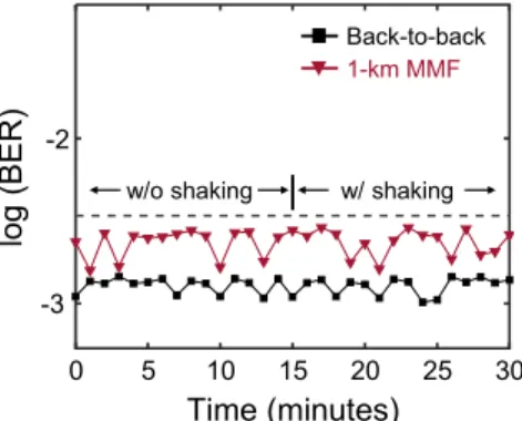
Fig. 6. Measured BER of the 112-Gb/s PAM4 signal in the back-to-back condition and after the transmission over 1 km of the OM2-type MMF with and without using the fiber shaker. In this measurement, the BER was measured at every minute.
These results indicated that, by utilizing the MCL technique, we could limit the power penalty of this 112-Gb/s PAM4 signal (operating at 852 nm) to be<1 dB even after the transmission over 1 km of the OM2-type MMF. This penalty was caused mostly by the chromatic dispersion. Thus, we concluded that the MCL technique could enable us to utilize the legacy MMF almost like an SMF even in the 850-nm band.
To evaluate the robustness of the MMF link implemented by using the MCL technique in the 850-nm band, we measured its BER performances under the effects of fiber bending and fiber shaking. For example, we wound the beginning portion of the 1-km long OM2-type MMF around a cylindrical post having a small radius of 1.2 cm and measured the power penalties of 112-Gb/s PAM4 signal as a function of the winding turns. The results in Fig. 5 showed that the power penalty caused by the fiber bending was negligibly small (since it was measured to be merely 0.15 dB even when we wound the MMF 20 times around the cylindrical post). We also measured the BER performance of 112-Gb/s PAM4 signal in the presence of fiber shaking. For this purpose, we placed a fiber shaker, consisted of a 3-m-long patch cord and a linear actuator moving at the speed of 3 Hz, at the front of the transmission MMF. The results in Fig. 6 showed that the performance of this MMF link was not affected by the fiber shaking. Thus, we concluded that the effects of fiber bending and fiber shaking could be neglected in the MCL-based MMF links operating in the 850-nm band (as in the 1.3- and 1.55-µm bands [5]).
26 IEEE PHOTONICS TECHNOLOGY LETTERS, VOL. 33, NO. 1, JANUARY 1, 2021
III. SUMMARY
We evaluated the possibility of utilizing the MCL technique in the 850-nm band. For this evaluation, we first realized the MCL technique by fusion-splicing the HI-780 pigtail fiber of MZM to the OM2-type transmission MMF under the optimum splicing conditions (i.e., the arc-discharge duration and fiber-push distance were set to be 17 s and 19 µm, respectively). The results showed that, despite the large difference in the mode-field diameters of the HI-780 fiber and OM2-type MMF, we could still achieve a high coupling efficiency of >92%. We then evaluated the frequency-response charac-teristics of the OM2-type MMF links implemented with the MCL technique. The measured frequency-response charac-teristics agreed well with the theoretically calculated curve obtained without considering the modal dispersion. From this result, we concluded that the MCL technique could be utilized in the 850-nm band as well to overcome the modal dispersion of the MMF link. By using the MCL technique, we also demonstrated the transmission of the 112-Gb/s PAM4 signal operating at 852 nm over 1 km of the OM2-type MMF. It should be noted that only a 9-tap FFE was utilized in this experiment. In addition, we confirmed that the performance of the MCL technique was quite robust against the mechanical perturbations, such as the fiber bending and fiber shaking, even in the 850-nm band.
REFERENCES
[1] D. Coleman, “Optical trends in the data center,” ICT Today, vol. 36, no. 5, pp. 16–22, Sep. 2015.
[2] IEEE Standard for Ethernet-Amendment 7: Physical Layer and Manage-ment Parameters for 400 Gb/s over Multimode Fiber, Standard 802.3cm-2020, Jan. 2020.
[3] IEEE Standard for Ethernet-Amendment 10: Media Access Con-trol Parameters, Physical Layers, and Management Parameters for 200 Gb/s and 400 Gb/s Operation, Standard 802.3bs-2017, Dec. 2017.
[4] J. Lavrencik, S. Varughese, J. S. Gustavsson, E. Haglund, A. Larsson, and S. E. Ralph, “Error-free 100 Gbps PAM-4 transmission over 100 m wideband fiber using 850 nm VCSELs,” in Proc. Eur. Conf. Opt. Commun. (ECOC), Sep. 2017, pp. 1–3.
[5] D. H. Sim, Y. Takushima, and Y. C. Chung, “High-speed multimode fiber transmission by using mode-field matched center-launching technique,” J. Lightw. Technol., vol. 27, no. 8, pp. 1018–1026, Apr. 2009. [6] M. S. Kim, B. G. Kim, S. H. Bae, and Y. C. Chung, “Effects of
multi-level format in MMF system based on mode-field matched center-launching technique,” IEEE Photon. Technol. Lett., vol. 30, no. 22, pp. 1972–1975, Nov. 15, 2018.
[7] M. Kim, B. G. Kim, H. Kim, and Y. C. Chung, “Transmission of 56-Gb/s PAM-4 signal over 2.3 km of MMF using mode-field matched center-launching technique,” in Proc. Opto-Electron. Commun. Conf. (OECC) Photon. Global Conf. (PGC), Jul. 2017, pp. 1–2.
[8] IEEE Standard for Ethernet-Amendment 3: Media Access Control Para-meters for 50 Gb/s and Physical Layers and Management ParaPara-meters for 50 Gb/s, 100 Gb/s, and 200 Gb/s Operation, Standard 802.3cd, Dec. 2018.
[9] G. J. Steckman, W. Liu, R. Platz, D. Schroeder, C. Moser, and F. Havermeyer, “Volume holographic grating wavelength stabilized laser diodes,” IEEE J. Sel. Topics Quantum Electron., vol. 13, no. 3, pp. 672–678, May 2007.
[10] R. Olshansky and D. B. Keck, “Pulse broadening in graded-index optical fibers,” Appl. Opt., vol. 15, no. 2, pp. 483–491, Feb. 1976.
[11] Z. A. Maricevic, T. K. Sarkar, Y. Hua, and A. R. Djordjevic, “Time-domain measurements with the hewlett-packard network analyzer HP 8510 using the matrix pencil method,” IEEE Trans. Microw. Theory Techn., vol. 39, no. 3, pp. 538–547, Mar. 1991.
[12] H.-Y. Kao et al., “Comparison of single-/few-/multi-mode 850 nm VCSELs for optical OFDM transmission,” Opt. Exp., vol. 25, no. 14, pp. 16347–16363, 2017.
[13] R. Puerta et al., “Effective 100 Gb/s IM/DD 850-nm multi- and single-mode VCSEL transmission through OM4 MMF,” J. Lightw. Technol., vol. 35, no. 3, pp. 423–429, Feb. 1, 2017.
[14] P. Zhang et al., “850 nm GaAs/AlGaAs DFB lasers with shallow surface gratings and oxide aperture,” Opt. Exp., vol. 27, no. 22, pp. 31225–31234, Oct. 2019.
[15] S. H. Bae, H. Kim, and Y. C. Chung, “Transmission of 51.56-Gb/s OOK signal using 1.55-µm directly modulated laser and duobinary electrical equalizer,” Opt. Exp., vol. 24, no. 20, pp. 22555–22562, Oct. 2016. [16] P. Bell, “Fiber selection guide for premises networks,” Corning, Corning,
NY, USA, White Paper WP1160, Sep. 2004.
[17] ITU-T Telecommunication Standardization Sector of ITU-Series G, Transmission System and Media, Digital Systems and Networks, doc-ument G.975.1, ITU-T Recommendation, Feb. 2004.