Development of Flow Mixing Header Assembly for Integral Reactor
Gyu-Mahn Lee,a Young-In Kim,a Woo-Seok Choi,a Jong-Wook Kim,a Kyeong-Hoon Jeong,a Tae-Wan Kim,a Jong-In Kin,a Ju-Hyeon Yoon, aa Korea Atomic Energy Research Institute, 150 Deokjin-dong, Yuseong gu, Daejeon 305-353, Korea
1. Introduction
In integral reactor, several steam generator cassettes are installed inside the reactor pressure vessel. If the simultaneous failure of one steam generate cassette section and the adjacent passive residual heat removal system occurs, the coolant temperature entering into the reactor core would be ununiform. To make the coolant temperature uniform, the FMHA (Flow Mixing Header Assembly) is developed by KAERI(Korea Atomic Research Institute). The FMHA is mechanical coolant mixing device installed between the steam generator cassette outlet and the core inlet in the reactor pressure vessel.
2. Background
Generally, twelve SGCs(Steam Generator Cassettes) are installed in the reactor pressure vessel of the integral reactor and classified into four separate sections of cooling loop. Each separate section consists of three adjacent SGCs and they are coupled with an independent feed water and a main steam line as shown in Figure 1. If one section of the SGC fails and an adjacent passive residual heat removal system is malfunctioned, it will make the coolant passing this SGC section and entering into the reactor core have locally higher temperature than the other sections. This phenomenon will cause non-uniform power distribution of the reactor core. To eliminate this phenomenon, the development of the FMHA is required.
3. Flow Mixing Header Assembly
The FMHA is a quadruple concentric conical shell structure, which has a lot of coolant flow holes. It is installed between the steam generator cassette and the reactor core. It helps mixing of coolant which flow out from the steam generate cassette and guiding the coolant to the reactor core. The FMHA shown in Figure 2 is designed to meet the requirements of Reference [1] and [2].
The FMHA consists of an external shell, an internal shell, a FMH(Flow Mixing Header), an outer guide shell, an upper plate, two seal rings, and FMH. The upper plate is an annular plate with twelve circular holes into which the bottom of the SGC is inserted. The upper plate guides the SGC vertically and provides a coolant path from the SGC outlet to the FMH inlet hole. The FMH is conical structure installed between the external shell and the internal shell. The outer guide
shell is a cylindrical shell that surrounds the external shell. It protects the reactor pressure vessel from excessive horizontal loads due to the thermal expansion of the FMHA.
The FMHA is divided into four sections of which configuration is the same to the SGC sections. The coolant from the SGCs flows separately into the corresponding FMHA's sections. The FMH has four layers in the vertical direction as shown in Figure 3. The first section of the coolant flows into the first layer, the second section of the coolant flows into the third layer, the third section of the coolant flows into the second layer, and the forth section of the coolant flows into the forth layer. The coolant into each layer can uniformly flow out through the outlet holes on the FMH's outer shell. The coolant from each layer is fully mixed in the outer region between the FMH outer shell and the internal shell. The size and location of coolant flow holes in the FMH inner and outer shells will be controlled for uniform coolant discharge.
4. Functional Verification
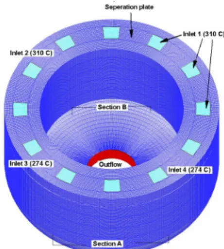
The flow of the FMHA was investigated numerically using a commercial CFD code, Fluent[3]. The porous media model, the k-epsilon turbulence model, the material properties of cold water, and the structure grids as shown on Figure 1 were adapted to simplify the structure of the FMHA and the flow pattern and to reduce the grid numbers. Through the CFD calculation of the radial distribution of the mass flow, the pressure loss coefficients of the porous media were revised repeatedly. The condition of a failure of two adjacent SGC sections was simulated. Figure 5 shows the temperature distributions at the section A and B of figure 4. The CFD results show that the temperature deviation of coolant entering into the reactor core has been remarkably reduced from 36℃ to about 7℃.
5. Conclusion
The FMHA is a unique design feature developed by KAERI to mix the coolant uniformly in the reactor pressure vessel. This structure shows highly effective performance for mixing the reactor coolant in the integral reactor and improving core performance when single section of SGC fails in conjunction with a malfunction of an adjacent passive residual heat removal system. The FMHA can reduce the fuel temperature by providing a fully mixed coolant into the Transactions of the Korean Nuclear Society Autumn Meeting
reactor core with rather uniformly distributed temperature.
6. Acknowledgement
This project has been carried out under the Nuclear R&D program by MOST.
REFERENCES
[1] Korea Electric Power Industry Code, MNG, Core Support Structure, 2000 edition..
[2] ANSI/ANS-51.1, American National Standard Nuclear Safety Criteria for the Design of Stationary Pressurized Water Reactor Plants, 1983.
[3] Fluent 6.1 User’s Guide, Fluent Inc., 2003.
Figure 1. Sections of SGCs in the integral reactor
Figure 2. Flow mixing header assembly
Figure 3. Section view of the flow mixing header
Figure 4. Grid and boundary conditions
(a) Section A
(b) Section B