INTRODUCTION
Since the radiation generator was developed by Roentgen in 1895, its use has continued to increase day by day. Linear accelerators evolved significantly with RF technology devel-oped during World War II after the initial attempts by Wid-eröe and Lawrence and Sloan(Wideröe 1928; Lawrence and Sloan 1931; Martins et al. 2014).
X-ray generators are routinely used in the medical field.
Recently, electronic accelerators have been used in various ways to improve product quality(Lawrence et al. 1931).
The Advanced Radiation Technology Institute(ARTI) in the Korea Atomic Energy Research Institute(KERI) intends to conduct empirical research to industrialize radiation appli-cation technologies already developed at the laboratory scale. An electron beam accelerator capable of continuous radiation treatment was installed at the Advanced Radiation Research Institute in 2018. The accelerator is a 10MeV energy elec-tronic accelerator manufactured by Mevex of Canada with a current rating of 3mA. The accelerator is equipped with a
Performance Qualifications for the Beam in a 10
MeV
Electron Accelerator
Yunjong Lee1,*, Jin-Mun Yun1, Youn-Mook Lim1, Byungnam Kim1 and Sang young Lee2 1Korea Atomic Energy Research Institute(KAERI), 1266, Sinjeoung-dong, Jeongeup-si,
Jeollabuk-do 56212, Republic of Korea
2Seoul Radiology Services(SRS), 37-19, Maengdongsandan-ro, Maengdong-myeon, Eumseong-gun, Chungcheongbuk-do 27733, Republic of Korea
Abstract - The Advanced Radiation Technology Institute(ARTI) introduced an electron beam
accelerator capable of continuous radiation processing in 2018. The instrument can be used for empirical research to industrialize already developed radiation technologies. Radiation processing has minimum absorbed dose requirements and maximum absorbed dose limits. It is important for radiation accelerators to maintain constant values for the device̓s operating parameters to meet
the absorbed dose required by the product(AAPM 1998). Therefore, an inspection(Performance
Qualification) of the accelerator performance is required, and the operation values of all processes
need to be set so that the absorption dose requirements can be met(ISO/ASTM International 2015).
To maintain dose requirements during the process, the processing variables need to be controlled:
electronic energy, beam current, and parameters according to material handling(transfer vehicle
speed or survey time), beam width, and characteristics of the processing process and conditions of
investigation(Chilkulwar 2012). In this study, the performance test of the electron-ray accelerators
presented by the international standards of ISO/ASTM was carried out. Assessments include
Electron Beam Energy, Average Beam Current, Beam Size(Beam Spot Size), Spoken Size and
Homogeneity(Scan Size and Uniformity of Unit), and Moving Dose Assessment(Uniformity). This
allowed individual measurements to be obtained within the allowable range for each item specified in ISO/ASTM 51649. Periodic inspection procedures will need to be established to maintain a constant dose for the devices (Zofia and Slawomir 2008) .
Key words : Performance qualifications, Dosimetry, E-beam, Accelerator, CTA film, B3, Dose distribution
─ 333 ─ * Corresponding author: Yunjong Lee, Tel. +82-63-570-3270,
large conveyor 2m wide and 20m long to enable radiation treatment of large objects.
Electrons, unlike photons, have unique characteristics in their interaction with matter as particles. The electrons have mass, and energy is transferred to the material through two interactions with the material: collisions and radiation. The radiation treatment process using these electron beams has a minimum absorbed dose requirement and a maximum ab-sorbed dose limit. It is important to keep the device operating parameter values constant so that the radiation accelerator can meet the absorbed dose required by the product(AAPM 1998; Soares 2007).
Therefore, after the accelerator installation was completed, performance qualification of the device should be performed (Meissner 1999). The process parameters obtained through this operating qualification should be set so that the absorbed dose requirements can be met(IAEA 2000; Miller et al. 2019).
The processing parameters that need to be controlled for the absorbed dose during radiation processing are as follows: electron energy, beam current, parameters(conveyor speed or irradiation time), beam width, process load characteristics and irradiation conditions.
MATERIALS AND METHODS
This study was conducted on a 10Mev electron radiation accelerator installed in a building in the ARTI. The model name of the device is MB10-30, and was manufactured by Canada’s MEVEX; the installation was completed in October
2018. The evaluation was carried out in accordance with the procedure described in ISO/ASTM 51649 to obtain the re-sults of the characterization of the electron beam.
A total of eight items were evaluated: Electron Beam Ener-gy, Average Beam Current, Beam Spot Size, Scan Size, Scan Uniformity, and Travel Uniformity, Dose-Speed Linearity Characterization, and Process Interruption for measuring the continuity of the dose due to beam downtime.
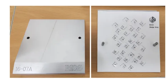
Rp and R50 were measured using film dosimeters(B3) provided by Riso and GEX as shown in Fig. 1(Butson et al. 2003). The operating conditions of the accelerator were a PRF of 618Hz, a beam average current of 3022μA, and a scan speed of 4Hz. The driving values did not change during the measurement. Rp and R50 values obtained using aluminum wedges were calculated using eq. 1 and eq. 2. At least three measurements of EA were made.
Ep=(5.09×Rp)+0.20 (eq. 1)
EA=6.20× (R50) (eq. 2)
An aluminum beam stop under the accelerator window was used to obtain the average amount of current in the beam. The resistor value of the aluminum block was measured and a beam pulse signal was obtained through the oscilloscope from the beam stop to the ground through the load resistor. The amplitude of the beam pulse VB was measured, and the peak beam current IB(A) was calculated by substituting eq. 3.
VB
IB=--- (eq. 3)
RL
To measure the beam spot size, CTA film was attached as
shown in Fig. 2 and 25kGy was irradiated on the film. The beam spot size is usually defined as the width with half the value(FWHM) of the dose maximum, and the beam spot is rotationally symmetric.
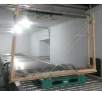
The scan width of the accelerator electron beam should be at least 2300mm for large products, as shown in Fig. 4. and typically at 2000mm or greater on the conveyor surface, as shown in Fig. 3. The uniformity of the beam scan was tested to satisfy more than 90% of the maximum dose measured at the scan width. The measurement was repeated several times.
Dose uniformity during product movement was measured at the bottom of the accelerator window. The average dose absorbed during travel should be within a range of ±5%. In this experiment, a CTA film was used. The film was allowed to pass in a direction perpendicular to the beam(Teixeira and Caldas 2002).
For the relationship between the conveyor speed and dose below the beam, the rate of the transfer vehicle was measured in a range of 0.3m·min-1 to 7.5m·min-1 to derive the func-tion between the speed and the dose. As shown in Fig. 4, the test was conducted using a 10MeV phantom and a B3 dosim-eter specified in ISO / ASTM 51261.
Sudden interruption of the accelerator beam may lead to
failure to meet the product’s intended absorbed dose. The ac-celerator consists of an interlocked system between beam ir-radiation and conveyor movement speed, and the dose change due to the change of the conveyor speed during stop and re-start was measured. In this test, the dose range was over 50 cm. The measurement surface was determined to be the one with the greatest effect of process interruption. The CTA film was attached to the product and placed at the centerline where the beam was drawn out. The emergency stop was performed
Fig. 2. A picture for the beam spot size measurement.
Fig. 3. Photograph of a scan quality experiment on the surface of a conveyor.
Fig. 4. Photograph experimenting with scan quality of large products.
Fig. 5. Photograph to evaluate the travel uniformity of the dose during the movement of the product.
Table 1. Measurement of continuity variation of dose according to process interference
Measurement position Conveyor surface
Measurement position Conveyor surface
Method of interruption or parameter tripped Beam clamp Persist counts of parameter tripped 0.2s Distance of test surface from scan horn 2050
after half of the total length was determined in consideration of the conveyor speed, and then the dose was measured by restarting the accelerator again. The accelerator was operated under the conditions shown in Table 1 to see the change in dose continuity due to process interruption.
A 24-hour endurance test was performed with the acceler-ator running at 95% or higher. The acceleracceler-ator conveyor sys-tem was also operated for 24hours. Possible stop situations
and their delay times were measured. Operation variable values during operation were BEAM_CLAMP_1, BEAM_I_ AVERAGE, PRF, PFN_V, KLY_PUL_I, RF_FWD, RF_REF, RF_FREQ, which were recorded. To measure all these vari-ables, measuring instruments were used as shown in Table 2.
RESULTS AND DISCUSSION
1. Beam energy
The beam energy was measured at 10.14, 10.14 and 10.13, using the film dosimeter(Model B3000) provided by Riso and GEX. The average was calculated at 10.14MeV. This value met the acceptance criteria of 10MeV±0.5MeV.
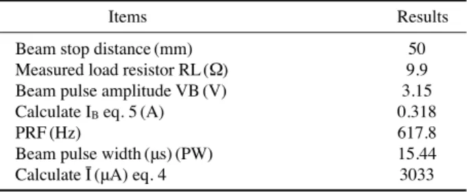
2. Average beam current
In this test, the distance between the beam window and the beam stop was 5cm. The RL value obtained through the oscilloscope was 9.9Ω, and the VB value, the beam pulse amplitude, was measured at 3.15V. The calculated results by
Fig. 7. Dose distribution curve by depth of aluminum wedge.
Table 3. Experimental results of average beam current
Items Results
Beam stop distance(mm) 50
Measured load resistor RL(Ω) 9.9
Beam pulse amplitude VB(V) 3.15
Calculate IB eq. 5(A) 0.318
PRF(Hz) 617.8
Beam pulse width(μs)(PW) 15.44
Calculate Ī(μA) eq. 4 3033
Table 4. Experimental values for obtaining beam spot size Position Conveyor surface Large productsurface Distance from scan horn
to dosimeter(mm) 2000 300
10 MeV Cross-plane
spot dimension(mm) 340.7 44.2
Fig. 6. Picture of 10 MeV calibration phantom allowing alanine do-simeters and thin-film routine dosimetry system dodo-simeters to be irradiated at the same position on the depth-dose curve.
the evaluation conditions.
3. Beam spot size
The beam spot size was measured on the conveyor in the direction of intersection with the 10MeV beam. The beam
window was measured at 340.7mm and the beam spot size at the top of the product at a distance of 30cm from the beam window was measured at 44.2mm. Experimental conditions and results are given in Table 4.
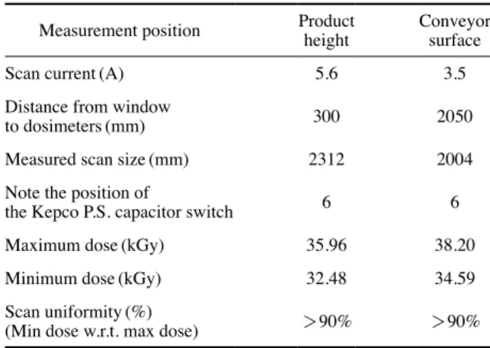
4. Scan size and uniformity
After placing the CTA film on a flat wooden surface, the beam irradiation uniformity test was carried out on the con-veyor surface. A 30kGy dose was irradiated, and the result of the measurement was that the beam scan width was 2004 mm and the beam width at the top of the larger product was 2,312mm. In both cases, the beam uniformity was measured at over 90%. The experimental conditions and results for the scan size and uniformity of the beam are given in Table 5.
5. Dose uniformity during product movement
The purpose of this test was to check dose uniformity on the surface of the product according to product motion while the beam was irradiating. After attaching the CTA film to the top of the product, the experiment was carried out. As a result of reading the CTA film, satisfactory results were obtained within ±5% as shown in Table 6.
6. Dose-speed linearity characterization
Tests were conducted for 0.3, 1.0, 3.0 and 5.0m·min-1 at typical UBC speeds used in daily operation. Three mea-surements were taken and the average values were
calculat-Table 6. The results of an assessment of the travel uniformity of the dose during the movement of the product
Dosimeter position Conveyor surface
Distance from window to dosimeters(mm) 2050
Conveyor speed(m·min-1) 0.3
Maximum dose along travel direction(kGy) 37.53 Minimum dose along travel direction(kGy) 35.91 Average dose along travel direction(kGy) 34.57
Travel uniformity(%) +4.5/-4.7
Table 7. Results of dose-speed linearity characterization UBC speed
(m·min-1) Inverse UBC speed(min·m-1) Trials and dose(kGy) Average dose(kGy)
1 2 3
0.3 3.333 38.625 36.375 37.225 37.41
1.0 1.000 10.300 10.475 10.225 10.33
3.0 0.333 3.500 3.450 3.400 3.45
5.0 0.200 2.300 2.400 2.350 2.35
7.5 0.133 No readings-Dose was below calibration curve minimum
Table 5. Experimental results on the scan size and uniformity of the beam
Measurement position Productheight Conveyorsurface
Scan current(A) 5.6 3.5
Distance from window
to dosimeters(mm) 300 2050
Measured scan size(mm) 2312 2004
Note the position of
the Kepco P.S. capacitor switch 6 6
Maximum dose(kGy) 35.96 38.20
Minimum dose(kGy) 32.48 34.59
Scan uniformity(%)
(Min dose w.r.t. max dose) >90% >90%
Table 8. Process interruption data for interruption at conveyor surface UBC speed
(m·min-1) Trial 1 Trial 2 Average
% U.D. % O.D. % U.D. % O.D. Ave % U.D. Ave % O.D.
0.3 8.5 7.5 5.9 8.1 7.2 7.8
0.6 7.0 7.3 9.4 9.3 8.2 8.3
The Process Interruption test was performed twice for each conveyor speed. After stopping the process, the conveyor was restarted without changing the position of the measuring device on the conveyor. The Maximum Over Dose(% O.D.) and the Under Dose(% U.D.) were calculated to determine the deviation from the reference dose in each test to distin-guish the effects of beam irradiation interruption from other variables.
100×(Max dose-Reference dose)
% O.D.=---Reference dose (eq. 4) 100×(-Min dose+Reference dose)
% U.D.=---Reference dose (eq. 5)
8. Endurance test
Accelerator endurance tests were performed to determine if the instrument was able to operate normally at more than 95% over 24 hours. The results of tests indicated that, the system operated for 24 hours without interruption, so there was no device off or delay time.
CONCLUSION
Through this study, all eight of the verification items were satisfied. To ensure the stable operation of the accelerator, it is necessary to continuously evaluate the eight items. In addi-tion, other test methods specified in ISO / ASTM 51649 need to be performed periodically. In particular, it was concluded that Dose-Speed Linearity Characterization should be con-ducted at least once a week to ensure that the performance of the equipment is stable. In the future, the Beam Spot Size
American Association of Physicists in Medicine. 1998. Radio-chromic Film Dosimetry, AAPM Report No. 63. Radiation Therapy Committee Task Group No. 55.
Soares CG. 2007. Radiochromic film dosimetry. Radiation
Mea-surements 41:S100-S116.
International Atomic Energy Agency. 2000. Gamma Irradiators for Radiation Processing, Vienna, Austria.
ISO/ASTM International. 2015. Practice for dosimetry in an electron beam facility for radiation processing at energies between 300keV and 25MeV, ISO/ASTM 51649:2015(E). Lawrence EO and Sloan, D. 1931. The production of heavy
high-speed ions without the use of high voltages. Phys. Rev. 38:2022.
Martins MN and Silva TF. 2014. Electron accelerators: History, applications and perspectives. Radiation Physics and
Chem-istry 95:78-85.
Teixeira MI and Caldas LVE. 2002. Dosimetric properties of various colored commercial glasses. Applied Radiation and
Isotopes 57:407-413.
Butson MJ, Yu PKN, Cheung T and Metcalfe P. 2003. Radio-chromic film for medical radiation dosimetry. Materials
Sci-ence and Engineering R41:61-120.
Miller A. 2019. Dosimetry for Electron Beam Applications. Risø National Laboratory, Risø-M, No. 2401.
Chilkulwar RH, Sharma SD, Chaudhary N, Acharya S, Mayya YS, Mittal KC and Gantayet LM. 2012. Dosimetric evalu-ation of an indigenously developed 10MeV industrial elec-tron beam irradiator. Radiation Measurements 47:628-633. Wideröe R. 1928. Über ein neues Prinzip zur Herstellung hoher
Spannungen. Archiv für Elektrotechnik 21:387-406. Zofia PS, Slawomir F. 2008. A comparison of the performance
characteristics of four film dosimeters in a 10-MeV electron beam. Applied Radiation and Isotopes 66:346-352.
Received: 19 September 2019 Revised: 3 October 2019 Revision accepted: 19 October 2019