Development of a Wall-Climbing Drone
Capable of Vertical Soft Landing Using
a Tilt-Rotor Mechanism
WANCHEOL MYEONG AND HYUN MYUNG , (Senior Member, IEEE)
Urban Robotics Laboratory, Korea Advanced Institute of Science and Technology, Daejeon 34141, South Korea Corresponding author: Hyun Myung ([email protected])
This work was supported in part by the Ministry of Land, Infrastructure and Transport of Korean Government through the Construction Technology Research Program under Grant 16SCIPC116873-01 and in part by the National Research Foundation of Korea through the Ministry of Science and ICT for the First-Mover Program for Accelerating Disruptive Technology Development under Grant NRF-2018M3C1B9088328.
ABSTRACT Wall-climbing drones have many applications, including structural health monitoring of civil structures, such as bridges and high-rise buildings, cleaning of solar panels to improve power generation efficiency, and airplane visual inspections. For these applications, the drone requires a high-payload capacity, and consequently the size and weight of the drone increase. The drone also should not damage the target structures considering the purpose of its mission. Our previous versions of a wall-climbing drone could have high-impact force on the surface where the drone perches and on the platform itself because of the impact caused by a fast pose change and landing speed. In order to overcome this potential risk, a mechanism and a control algorithm for perching on a vertical surface through low-speed pose change are proposed in this paper. The drone platform is based on an X-configuration quadcopter, and a tilt-rotor mechanism is incorporated into the two axes, such that the front thrusters and the rear thrusters are paired. The vertical soft landing mechanism using the tilt-rotors is validated by the experimental tests of the prototype.
INDEX TERMS Soft landing, tilt-rotor, wall-climbing drone, wall-perching.
I. INTRODUCTION
WAll-climbing robot technology has drawn constant attention in the field of mechanical engineering and robotics society due to its numerous possible applications. Recently, some companies have launched commercial wall-climbing robots for cleaning walls [1], [2] or solar panels [3], [4]. However, wall-climbing technology still has limitations in that it is impossible to move along a separated façade or an irregular surface. The most important requirement for a wall-climbing robot for practical use is the stability to adhere to the wall and the reliability to prevent falling accidents. One promising solution for this is to apply normal force to the wall. For the inspection of civil structures exposed to harsh environmental conditions such as strong winds, this approach allows an aerial robot to stably cling to the wall [5], [6]. When the drone fails to attach to the wall, this mechanism can help the drone re-attach to the wall by generating a pushing force [7], [8].
The wall-climbing system should be thoroughly prepared for falling accidents by system failures because an acci-dent caused by system failure of a wall-climbing robot is
potentially very dangerous causing damage to the robot and harming pedestrians. In order to overcome these limitations, the concept of a wall-climbing robot based on a drone plat-form, called CAROS (Climbing Aerial Robot System), has been proposed and developed before [8]. This robot plat-form can fly like commercial drones, as well as perch on a wall by changing its pose, and climb the wall. Traditional wall-climbing technologies such as magnetic [9], a suction module [10], [11], adhesive material [12]–[14], mechanical claws [15], a microspine [16], pneumatic-adhesion [17], [18], and tether-supported climbing methods [19], [20] are gener-ally dependent on the material or the shape of the surface. The original motivation for developing CAROS was to create a wall-climbing robot that is unaffected by the wall condition like surface material or shape. Wall-climbing mechanism using the friction force generated by normal force to the wall could be the solution because the force naturally pushes the robot to the wall and the friction exists almost everywhere.
However, considering that the wall-sticking mechanism is based on the friction force at contact points, which is caused
4868
2169-3536 2018 IEEE. Translations and content mining are permitted for academic research only.
by the normal force to the wall generated by the thrust force for flight, the friction coefficient is a very important factor and the energy efficiency is greatly affected by the unknown friction coefficient. Due to the uncertainty of the surface condition, for example, the irregular shape or various contam-inants, ideal condition with a high friction coefficient cannot be assured. For the same reason, when CAROS perches on the wall, assuming a low friction coefficient, the pose of the drone should be swiftly changed with large thrust force to maximize the normal force to the wall. From the viewpoint of protecting the wall and the drone, impact from high speed for perching is not favorable.
To mitigate this problem, a novel transformable drone platform is proposed in this paper, where the direction of thrusters can be changed and the ratio between the normal force and the ascending force can be adjusted using tilt-rotors. Consequently, the drone less relies on a wall sticking condition and it does not need to change its pose with high angular speed to prevent slippage.
Many researchers have designed various types of drone platforms [21]–[23] along with their control strategies [24]–[26]. Also, they have developed tilt-rotor-based drones, some of which focus on the attitude and position control of the drone [27]–[29], and others apply tilt-rotor mechanism to wall-climbing robots [30]. Although the tilt mechanism for drones has high potential to broaden the application area, only a few commercial racing drones use tilt mechanism to increase the speed [31]. Because the payload of drones is very limited, an additional mechanism could decrease the operation time and the energy efficiency. Considering these limitations, we aim to develop a tilt-rotor-based wall-climbing drone using a minimum number of actuators. Using only two actuators, the drone is designed to perch on the wall with gentle motion and climb the wall with higher energy efficiency than the previous CAROS.
Section II introduces the basic mechanisms and strate-gies for vertical soft landing and wall-climbing. Section III elaborates the structure of the prototype drone. Finally, in order to show the feasibility of the proposed mecha-nism, wall-perching and wall-climbing tests are performed and the results of the experimental tests are shown in Section IV.
II. STRATEGY FOR VERTICAL SOFT LANDING
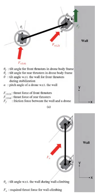
Throughout this paper, we define the symbols as shown in Fig.1.
The soft landing procedure is aimed at low-impact perch-ing on vertical walls such as façades of high-rise build-ings, and it consists of three steps: stabilization process, pose change, and being ready for wall-climbing (stick-ing) mode. For perching, the drone changes its pose along the pitch angle direction using only two actuators for the tilt-rotor mechanism. The angular range of the tilt
mech-anism is 180◦ in order to make the direction of the
thruster normal to the wall when the drone sticks to the wall.
FIGURE 1. A free body diagram and used symbols during (a) stabilization process and pose change (b) wall-climbing.
A. STABILIZATION PROCESS
For safe landing on a vertical surface, a stabilization concept was already proposed by a few researchers. Before changing its pose, in order that the first contact point is fixed to the wall and acts as a hinge point, various perching mechanisms such as suction cups and an adhesive gripper were developed in [32] and [33]. The stabilization method of our proposed system is conceptually similar to the wall-sticking principle of CAROS.
Once the drone contacts its head to the wall, it starts to change the tilting angle of thrusters adjacent to the wall, gen-erating frictional force between the drone and the wall. This state is similar to the state of wall-sticking of CAROS except that the remaining thrusters still try to maintain the hovering
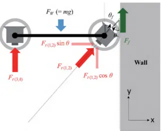
FIGURE 2. A free body diagram in the stabilization process.
state of the drone. Without loss of generality, we assume that the wall is perfectly vertical. When the tilting angle,θ, is 90◦, that is, the direction of thrust force is normal to the wall, all the thrust force is used for making frictional force, as in CAROS. This is not a favorable condition with a low friction coefficient because a large normal force is required, as briefly mentioned in Section I. Therefore, assuming that the drone only uses the same level of thrust force as in the hovering state, the drone can maintain the force equilibrium against gravity by changing the tilting angle for stabilization. The FBD (Free Body Diagram) in Fig.2 can be formulated as follows:
mg = FW
= Ft(1,2)cosθ + Ff + Ft(3,4)
= Ft(1,2)cosθ + µFt(1,2)sinθ + Ft(3,4)
=0.5mg cos θ + 0.5µmg sin θ + 0.5mg (1)
whereθ is the tilt angle for stabilization, m the mass of the drone, g gravitational acceleration, FW the drone’s weight,µ
static frictional coefficient, and Ff friction force. Ft(1,2)and Ft(3,4)are the sum of thrust forces of the front part leaning on
a wall and the other rear part, respectively. Ft(1,2)and Ft(3,4)
are assumed to be 0.5mg, which means they are respectively holding half of the weight of the drone, as in a hovering state. From (1), the relationship between the friction coefficient and the required tilting angle is described by (2) and plotted in Fig.3.
µ = 1 − cosθ
sinθ (2)
While the tilting process is performed, a PID (Proportional Integral Derivative)-based flight controller still operates in the same manner as normal flight status. Therefore, if slip-page is detected by measuring the angular acceleration from an IMU (Inertia Measurement Unit), the thrust level at the front side naturally increases. When the ratio of the front thrust to rear thrust is over a specific threshold, the drone
FIGURE 3. The relationship between the friction coefficient (µ) and the required tilting angle (θ).
stops tilting and proceeds to the next step. The friction coef-ficient is approximately estimated by the maximum tilting angle by (2).
Theoretically, if the friction coefficient is 1, the tilting angle can be 90 degrees. However, since this aerial drone plat-form is based on an X-configuration quadrotor (see Fig. 4(a)), the airflow from front thrusters is obstructed by the rear structure of the drone with 90 degrees tilting angle, as shown in Fig. 4(b). Then it is difficult to deal with accidental slippage with limited angular speed of the tilt-rotor mechanism. There-fore, as in Fig. 4(c), the tilting angle should not be 90 degrees, but rather about 35 to 45 degrees practically, which is also related to the pose change process.
B. POSE CHANGE
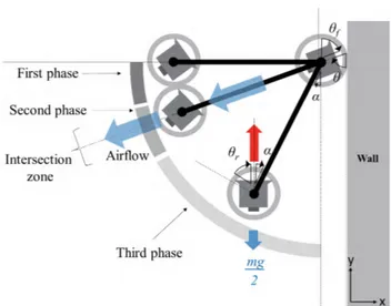
Though stabilization process is not affected by the obstruc-tion of airflow, obstrucobstruc-tion is inevitable during pose change process because of the X-configuration design. In this paper, if the air obstruction occurs at a specific pose of the drone, we define it as an intersection zone. The range of the inter-section zone is determined byθ as shown in Fig. 4(c).
As shown in Fig.5, to control the tilting angle to the wall, θ, we have to determine the range of intersection zone and other phases as well. Before the second phase of entering the intersection zone, the drone starts to change its pose while maintaining the direction of the forward thrusters against the wall. At the same time, the tilting angle of the tail-side thrusters,θr, becomes (90 −α)◦as the direction of thrusters
becomes vertical whereα is the pitch angle of the drone to the wall that can be acquired from the IMU. This posture is advantageous to prevent falling accidents by aligning rear thrusters to the direction of gravity force. With this condition, the angle of the rear thrusters increases as the pitch angle to the wall,α, decreases as follows: θr =90 −α.
Regarding the range of the intersection zone, θr should
FIGURE 4. Obstruction of airflow in an X-configuration quadrotor layout design (a) Top view (b) Side view when tilting angle is 90◦(c) Side view
with different tilting angle.
with the direction of the airflow of thrusters at the front side and prevents the sidewall of the rear thruster from directly blocking the airflow. Under this condition, smaller tilting angle of forward thrusters,θf, is better as long as the sticking
force to the wall is sufficient. Otherwise, large tilt angle leads to obstruction of the airflow, which can lead to falling by slippage.
Another strategy to overcome air obstruction in the inter-section zone is to decrease the duration in the interinter-section zone by rapidly increasing the angle of the forward thrusters to the wall at the moment of entering the intersection zone, as described in Fig.5.
After passing the intersection zone, assuming the first con-tact point is a hinge support, the thrust force Ft(3,4) causes
a torque and the drone’s body leans toward the wall. The torque at the first contact point A, TA, is expressed as follows
FIGURE 5. The pose change process (tail-down) and FBD for the torque. Angle symbols are expressed for the third phase exceptθf for the first
phase.
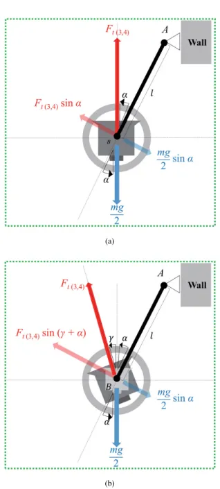
(see Fig. 6(a)):
TA= l · ( mg
2 sinα − Ft(3,4)sinα) (3)
where l is the body length of the drone.
However, as the pitch angle of the body α decreases, the thrust force may not generate the torque for pose change, since TAapproaches to 0 whenα approaches to 0. We define
pitch offset angle γ as the additional tilt angle for rear thrusters to generate the torque for pose change, as described in Fig. 6(b). We determineγ in the attitude control mecha-nism for the third phase. Depending on the angleγ , the torque can be generated as follows:
TA= l · ( mg
2 sin(α + γ ) − Ft(3,4)sinα). (4) For the attitude control, two PID controllers are used for controlling Ft(3,4) and γ , respectively. The pose error ˜θ is
calculated as follows: ˜
θ = θd− ˆθ (5)
whereθd is the target pitch angle of the drone and ˆθ is the
drone’s current pitch angle estimated from the IMU. Then, the control values of the rear thrust levelδt(3,4)and pitch offset
angleδγ are calculated based on the pose error ( ˜θ) as follows: δt(3,4)= KPtθ + K˜ It
Z t 0
˜
θdt + KDt˙˜θ (6)
where KPt, KIt, KDtare coefficients for the proportional,
inte-gral, and derivative terms for thruster control, respectively, and δγ = KPγθ + K˜ Iγ Z t 0 ˜ θdt + KDγ˙˜θ (7)
where KPγ, KIγ, KDγ are coefficients for the proportional, integral, and derivative terms for pitch offset angle control, respectively.
FIGURE 6. (a) FBD without pitch offset angle (b) FBD with pitch offset angle.
C. WALL-CLIMBING MODE
After a pose change, in order for the airframe to stay on the wall with minimum thrust force, the drone enters the wall-climbing mode. Under the thrust level same to the hovering state, it adjusts the direction of all thrusters with the estimated friction coefficient from the stabilization process. According to the relationship between the friction coefficient and the required tilting angle in Fig. 3, the direction of thrusters is calculated. Another purpose of the tilt mechanism is to climb the vertical wall efficiently. The tilt mechanism helps the drone stick to the wall with a low friction coefficient by mitigating the dependency on the friction force generated by the normal force to the wall surface. The relationship between the required thrust force and the friction coefficient can be
FIGURE 7. (a) FBD for wall-climbing with tilting angle (b) Simulation results of a 3 kg weight drone (c) Detailed plot of the required thrust force at the hovering state.
represented as follows: Fa = mg Ff +cosθa = mg µ sin θa+cosθa (8)
where Fa is the required thrust force for wall-climbing, θa
is the tilt angle with respect to the wall, and Ff is the
friction force caused by the normal force to the wall. Ff
is directly proportional to the friction coefficient µ. (8) is plotted in Fig.7 and it shows that the required thrust force drastically decreases as the tilt angleθadecreases in the low
friction coefficient environment. The plot in Fig.7assumes that the mass of a drone is 3 kg same as that of the prototype drone. Therefore the required force for hovering state is calcu-lated as 29.42 N to support the 3 kg weight drone. Depending on the friction coefficient, there is a range of tilt angle that requires small thrust force and a specific optimal angle with minimum required thrust force. Due to the reduced required thrust force, the energy efficiency can increase. Section IV includes the experimental tests to validate this simulation.
III. PROTOTYPE DESIGN
A. GENERAL DESIGN CONSIDERATION AS AN MAV
For flight stability, a general MAV (Micro Aerial Vehicle) has design principles and constraints. First, most drones con-sist of a main body at the center, support arms connecting thrusters with the main body, and landing gears. To maximize flight stability, the main body is located at the center of the drone to ensure that the center of mass is located at the center of the drone and to minimize the moment of inertia. Second, from the main body, support arms are arranged radially or symmetrically. The connecting material should be rigid and should not transfer vibration. If it is not rigid, the thrust force will not be fully delivered to the main body, and as a result a feedback controller such as the PID controller will not work well because of incorrect feedback information. Third, the parts containing heavy components such as the battery, electric devices, and landing gears should be placed near the center of gravity as long as they do not hinder pitch or roll motion. This condition increases flight stability and helps pose change with small thruster force.
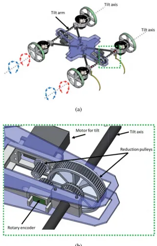
Under these design constraints of the typical MAV struc-ture, there are practical difficulties in applying the tilt-rotor mechanism. In particular, the propeller’s large diameter makes applying a tilt mechanism harder in that the propeller size increases in proportion to the payload according to the momentum theory or actuator disk theory. In order to carry 2,500 to 3,000 g of payload with a moderate flight time, the required propeller diameter is about 10 to 12 inches [34]. Like this, as a normal propeller requires large diameter and volume for tilting, a duct fan unit can be considered as an alternative. Most importantly, it can save space because of its smaller outside diameter of about 70 mm. The overall layout of the main body frame is based on a general X-configuration quadrotor. Two thrusters are connected with a tilt arm and rotate together along the tilt axis as shown in Fig. 8(a).
B. DESIGN OF TILT-ROTOR MECHANISM
As mentioned before, since the MAV has a limited payload and operation time, it is important to minimize the number
FIGURE 8. (a) Mechanical design for the drone’s transformation (b) Detail view of tilt mechanism.
of actuators and other mechanical parts (components) that support them. Therefore, the tilt-rotor mechanism should be implemented using the minimum number of actuators. In the proposed perching process, the thrusters are classified into two groups in terms of their role. One group is for stabiliza-tion, which acts as a hinge support for pose change, and the other is a group of thrusters at the opposite side, by which the drone generates the torque for pose change. In order to minimize the platform weight and complexity of control, the manipulation plan for the tilt mechanism is based on this grouping.
In order to realize the rotation of the tilt axis, a continuous rotation servo is employed; its weight is about 55 g, the stall torque is about 10 kg/cm, and operation speed is 300 deg/s. Combined with a 72/14 ratio reduction pulleys, the tilting axis rotates with maximum torque of 51 kgf·cm and angular speed of 58 deg/s, which satisfies the required specification. Pulley-belt drive systems could minimize a backlash problem which can cause an unstable body structure with vibration or angular error. For the same reason, a pulley-belt is also applied to the rotary encoder measuring tilting angles as shown in Fig. 8(b). Using servomotors with angular speed of 300 deg/s and a 72/14 ratio pulley system, the axis for tilting can rotate with
angular speed of 58 deg/s. The time for rotation of the remain-ing 90 degrees takes only 1.5 seconds.
C. ELECTRICAL PARTS AND CONTROL SYSTEMS
Fig.9 shows a block diagram of the electrical components of the control system, sensors, and actuators. In order to implement real-time flight control loop of the main MCU, the control system of the drone consists of two ATmega2560-based 8-bit MCUs (Micro Controller Units). As a main con-troller, one MCU is used for the control of all actuators such as thrust control for flight, tilt control, and wall-climbing drive control. The other auxiliary MCU for acquiring most sensor data is installed on the drone. The drone has two infrared distance-measuring sensors, two crash sensors, and two rotary encoders for the tilt angles. The data acquired from the auxiliary MCU is transmitted to the main MCU via serial communication. The only data that the main MCU directly obtains is IMU and remote control data for a corresponding flight control loop with fast update interval.
FIGURE 9. Electrical components for the drone control.
D. AUTOMATIC LANDING ASSISTANT
Considering that the pitch and yaw angle in the body frame is very small in a moderate flight state, the drone has two sonar sensors measuring the distance to the wall, DL, DR, and
calculating the approaching angle to the wall, τ, as shown in Fig. 10(a). When the drone detects a specific distance of about 10 to 150 cm from the wall, the landing assistant system is activated to make the drone’s heading normal to the wall by decreasing the approaching angle and maintaining the altitude from the ground. This self-alignment system is working in the high-level flight controller for yaw motion control and thrust level control by using z-axis acceleration and altitude information H , as illustrated in Fig. 10(a).
Once the drone maintains steady contact to the wall for a period of time, it starts the landing procedure by starting stabilization process. This steady contact situation can be described by the following conditions:
D(L,R) ≤ Dth C(L,R) = TRUE
Acc(x,y,z) ≤ |Accth| (9)
FIGURE 10. (a) The drone approaching the wall with an approach angle (b) A flow chart of vertical soft landing control.
where D(L,R), Dth, C(L,R)are distance data from distance
sen-sors such as infrared or ultrasonic distance sensen-sors installed at the left and right-side of the drone, the threshold value for
distance, tactile sensor data installed at the front left and right of the drone, respectively. Acc(x,y,z)are the acceleration data
along x, y, and z axes of the drone’s body frame and Accthis
the threshold value for the acceleration limit. We have used Sharp GP2Y0A60SZL for distance sensors whose measuring distance is 10 to 150 cm, so that the drone starts to align its direction of approaching angle from about 150 cm distance to the wall.
In Fig. 10(b), the overall process of vertical soft land-ing is shown. In step 1 of the control algorithm, the drone reads sensor data D(L,R), C(L,R), and Acc(x,y,z). Using D(L,R),
the drone computes approach angle,τ, as in Fig. 10(a) and adjusts the heading angle of the drone to be aligned with the wall. At the same time, the drone checks whether the front part of the drone contacts to the wall for the stabilization process. In step 2, the drone starts the stabilization process and measures tilt angle of front thrusters to determine whether the stabilization process is finished. In step 3, after the sta-bilization process, the drone proceeds to the second phase of pose change before the intersection zone. As mentioned before, the obstruction area is determined by tilting angle to the wall θ. The drone can determine whether the drone is before or after the intersection zone by comparingθ with the pitch angle of the drone. Finally, in step 4, the drone starts the third phase of pose change right after the intersection zone. In this process, the drone decreases the pose change speed to the target speed and finally enters the final landing process. When the pitch angle of the drone reaches 90◦, the landing process is finished.
IV. EXPERIMENTAL TEST A. STABILIZATION TEST
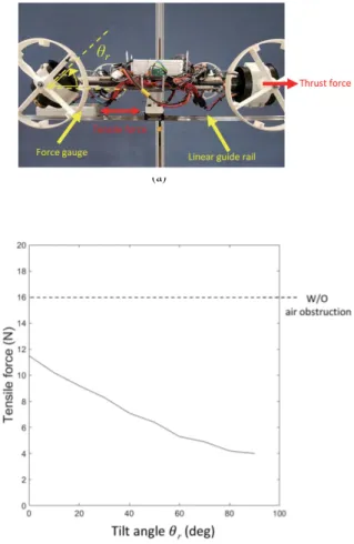
As mentioned before, during pose change, there is an inter-section zone where the airflow of the thrusters at the front side could be obstructed by the structures of the thrusters. The effect of decreasing thrust force caused by air passage obstruction is verified by an experimental test as shown in Fig.11. In the experiment, a drone is installed on a linear guide, on which the drone moves freely along the guide rail. The thrust force of right thrusters in Fig. 11(a) is set to 16 N equal to the hovering or stabilization level, and the tilt angle of the other thrusters,θr, confronting airflow of right thrusters
is varied from zero to 90 degrees. We used a force gauge to measure tensile force caused by thrust force of right thrusters to verify the effect of the air passage obstruction. Fig. 11(b) shows the result of experimental tests. The result shows that as the tilt angle becomes close to 90 degrees, the tensile force is decreased. On the contrary, the closer θr gets to
zero, the less air obstruction is caused and consequently the net thrust force increases. To overcome this platform limita-tion, we separated the pose change process into three phases depending on the intersection zone as in Fig.5.
B. PERCHING TEST
A perching experiment according to the tilt angle to the
wall, θ, was conducted with our prototype drone where
FIGURE 11. Experimental test for the effect of the obstruction of airflow. (a) Test setup. (b) Test results.
the friction coefficient between drone and the wall was about 0.5 to 0.7. The tilt angle ranges from 0 (no-tilt case) to 90 degrees, with increments of 10 degrees. As shown in Fig. 12, if the tilt angle is not sufficient, the perching fails. On the other hand, when the tilt angle is too excessive, it fails during the intersection zone of pose change, although stabilization is successful. With a full-tilting angle, it failed 10 times out of 10 trials as shown in Fig.12.
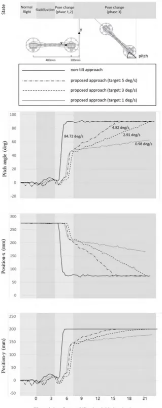
The main contribution of this work is to mitigate the impact of perching by controlling the pose change speed with a tilt-rotor-based airframe. Since the non-tilt approach only changes its pose as fast as possible to prevent falling by slippage, the impact could be high enough to damage the wall or the drone itself. Therefore, experimental tests are conducted to verify the performance of the mechanism and control algorithm by measuring the angular speed of the pose change and comparing it with that of a non-tilt approach. In the experiment, we set the target angular speed to 1.0, 3.0, and 5.0 deg/s for the proposed approach, and measure the angular speed with an IMU installed for flight control. The results are shown in Fig. 13. In the non-tilt approach, the drone just changes body pose until it sticks to the wall with the maximum pose change speed. However, the
FIGURE 12. Experimental results of perching tests. For each tilt angle, 10 trials are tested.
proposed approach is able to control its pose speed to follow the target speed after the intersection zone (phase 2). As for the soft landing, the data log includes the state of the perching from normal flight to pose change. While the pose is changed very rapidly during phases 1 and 2, the average angular speed is 0.98, 2.91, and 4.82 deg/s at the final state (phase 3), which is very close to the target speed of 1.0, 3.0, and 5.0 deg/s, respectively, as shown in Fig.13and Table1.
TABLE 1. Summary of the experimental test (unit: deg/s).
However, the non-tilt approach changes its pose
within 1.5 seconds and the average angular speed is about 84.72 deg/s, which is significantly higher than the soft landing approach. Consequently, the experimental tests show that the proposed system allows the drone to perch on a vertical wall with a desired angular velocity and guarantees a soft landing. In order to verify the effect of reduced perching impact, we installed an accelerometer on the drone and target wall, compared acceleration data, and calculated the impact for both approaches. Regarding the non-tilt approach, when the front part of the drone firstly contacts the wall, low level of impact force occurs as shown in Fig. 14(a). Within 1.2 seconds, a drone completes perching process by changing its pitch angle and the rest of its body bumps into the wall. The second contact causes high level of impact as shown in Fig. 14(a). The calculated impulse of the first and second contact was 0.90 and 4.76 kg·m/s, respectively.
On the contrary, in our proposed approach with the pose change speed of 5 deg/s, the impulse level of the first contact is the same with the non-tilt approach; however, the impulse from the second contact was significantly decreased to 0.05 kg·m/s. Fig.15shows an exemplary tail-down perching
FIGURE 13. Data for perching process.
process using a tilt-rotor mechanism and the video of overall experiments is available at https://youtu.be/ioh9MVeIWas/.
C. WALL-CLIMBING TEST
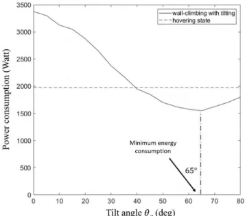
Wall-climbing tests are conducted to verify energy efficiency of tilt-rotor mechanism. The surface material of the wall is
FIGURE 14. Acceleration data of perching test (a) non-tilt approach (b) tilt approach.
FIGURE 15. Experimental test for the proposed perching (a) the first contact and starting stabilization (b, c) pose change (d) the second contact and completing perching process.
tempered glass and the material of the wheel surface is 1 mm-thick silicone sheet. By using a force gauge, the average friction coefficient between them is measured to be 0.53. According to the tilting angleθain Fig. 7(a), we measured
power consumption at wall-climbing condition with constant
FIGURE 16. Power consumption data for wall-climbing test.
velocity of about 0.1 m/s. Power consumption is measured by an electric current and voltage sensor. The test range of the tilting angleθais from 0 to 80◦to secure minimum pushing
force to the wall. When θa reaches 90◦, there is no force
that makes the drone stick to the wall. The results are shown in Fig.16. From 40 to 80◦of tilt angle, the drone can climb the vertical wall with lower energy consumption than that of the hovering state. When tilting angle is 65◦, the drone consumes the lowest energy. These results are consistent with the result of wall-climbing simulation when friction coefficient is 0.5. According to the simulation result in Fig. 7(c), a drone needs lower thrust force than the hovering state from 37 to 90◦and requires minimum thrust force with tilt angle of 63◦.
V. CONCLUSIONS AND FUTURE WORKS
The proposed tilt mechanism-based landing system shows the ability to perch on a wall with low angular speed of pose change and consequently it can reduce the landing impact significantly. In addition to that, in terms of thrust-assisted wall-climbing mechanism, the tilt mechanism can help a drone to stick to the wall with small thrust force by adaptively changing the direction of thrusters. In this study, we tried to implement the concept of the vertical soft landing mecha-nism using a quadrotor-based structure. Considering limited payload of a drone, we designed the tilt mechanism enabling both vertical soft landing and efficient wall-climbing using only two actuators. Though the X-configuration quadcopter structure can cause air obstruction when the tilting angle is 90◦, we overcame this hardware limitation with a dedicated control strategy.
Since it was difficult to apply the tilt mechanism using the normal propeller of general drones due to its large diameter, we applied EDF (Electric Ducted Fan) units with
small diameter. But it is disadvantageous that the energy efficiency of the EDF unit is lower than that of the normal propeller propulsion system. Furthermore, the structure with tilt mechanism cause an intersection zone, and consequently a specific control strategy is necessary and various pose states may not be possible. For these reasons, in the future, we need to develop a better platform structure that has enough space for tilting a large propeller and minimize the interference of airflow between two tilt units depending on various tilt angles.
Another purpose of the tilt-mechanism is to climb the vertical wall in that the tilt mechanism helps the drone stick to the wall with low friction coefficient by mitigating the dependency on the friction force generated by the normal force to the wall surface. However, in the wall-climbing test, it was found that friction force was readily decreased as the contact surface is worn out from rubbing or stained with contaminant like fine dust. For these reasons, it could be reasonable to consider very low frictional coefficient in real world application for thrust-assisted wall-climbing mecha-nism. Therefore, other future work is to develop and optimize the wall-climbing system for very low frictional coefficient using a tilt mechanism in terms of energy efficiency, climbing performance, and safety.
Since the tilt-rotor mechanism has only single degree of freedom with a fixed wheel drive aligned with the same direction, the drone platform is optimized for only vertical climbing. For lateral movement on the wall, there must be a mechanism that can change driving direction of the drone body or additional tilting mechanism is required for other axes. Considering the limited payload of the drone platform, it is challenging to simplify and implement the mechanisms for an improved design. Therefore, it is also a future work to design a tilt-rotor-based wall-climbing platform that allows omnidirectional movement.
NOMENCLATURE AND UNIT
θf tilt angle for front thrusters in drone body frame
(deg)
θr tilt angle for rear thrusters in drone body frame
(deg)
θ tilt angle with respect to the wall for front
thrusters
during stabilization (deg)
θa tilt angle with respect to the wall during
wall-climbing (deg)
α pitch angle of a drone with respect to the wall
(deg)
Ft(1,2) thrust force of front thrusters (N) Ft(3,4) thrust force of rear thrusters (N)
Ff friction force between the wall and a drone (N)
Fa required thrust force for wall-climbing (N)
FW the drone’s weight (N)
m the mass of the drone (g)
µ static frictional coefficient
REFERENCES
[1] ECOVACS. (2018). The Window Cleaning Robot (WINBOT). [Online]. Available: https://www.ecovacs.com/il/winbot-window-cleaning-robot [2] IlshimGlobal. (2018). Window Cleaning Robot (MYWINDORO). [Online].
Available: http://www.mywindoro.com/about/
[3] Miraikikai. (2018). Solar Cleaning Robot (MYWINDORO). [Online]. Available: https://www.miraikikai.jp/english
[4] SERBOT. (2018). Gekko Solar Robot (GEKKO Solar). [Online]. Available: https://www.serbot.ch/en/solar-panels-cleaning/gekko-solar-robot [5] J. Xiao, B. Li, K. Ushiroda, and Q. Song, ‘‘Rise-Rover: A wall-climbing
robot with high reliability and load-carrying capacity,’’ in Proc. IEEE Int. Conf. Robot. Biomimetics (ROBIO), Dec. 2015, pp. 2072–2077. [6] PRODRONE. (2018). Vertical Walls and Ceilings Inspector (PD6-CI-L).
[Online]. Available: https://www.prodrone.jp/en/concept/pd6-ci-l/ [7] M. T. Pope et al., ‘‘A multimodal robot for perching and climbing on
vertical outdoor surfaces,’’ IEEE Trans. Robot., vol. 33, no. 1, pp. 38–48, Feb. 2017.
[8] W. C. Myeong, K. Y. Jung, S. W. Jung, Y. H. Jung, and H. Myung, ‘‘Development of a drone-type wall-sticking and climbing robot,’’ in Proc. 12th Int. Conf. Ubiquitous Robots Ambient Intell. (URAI), Oct. 2015, pp. 386–389.
[9] K. Nagaya, T. Yoshino, M. Katayama, I. Murakami, and Y. Ando, ‘‘Wireless piping inspection vehicle using magnetic adsorption force,’’ IEEE/ASME Trans. Mechatronics, vol. 17, no. 3, pp. 472–479, Jun. 2012.
[10] H. Zhu, Y. Guan, W. Wu, L. Zhang, X. Zhou, and H. Zhang, ‘‘Autonomous pose detection and alignment of suction modules of a biped wall-climbing robot,’’ IEEE/ASME Trans. Mechatronics, vol. 20, no. 2, pp. 653–662, Apr. 2015.
[11] Y. Guan et al., ‘‘A modular biped wall-climbing robot with high mobility and manipulating function,’’ IEEE/ASME Trans. Mechatronics, vol. 18, no. 6, pp. 1787–1798, Dec. 2013.
[12] Y. Liu, H. Kim, and T. Seo, ‘‘AnyClimb: A new wall-climbing robotic plat-form for various curvatures,’’ IEEE/ASME Trans. Mechatronics, vol. 21, no. 4, pp. 1812–1821, Aug. 2013.
[13] M. P. Murphy and M. Sitti, ‘‘Waalbot: An agile small-scale wall-climbing robot utilizing dry elastomer adhesives,’’ IEEE/ASME Trans. Mechatron-ics, vol. 12, no. 3, pp. 330–338, Jun. 2007.
[14] T. Seo and M. Sitti, ‘‘Tank-like module-based climbing robot using pas-sive compliant joints,’’ IEEE/ASME Trans. Mechatronics, vol. 18, no. 1, pp. 397–408, Feb. 2013.
[15] W. R. Provancher, S. I. Jensen-Segal, and M. A. Fehlberg, ‘‘ROCR: An energy-efficient dynamic wall-climbing robot,’’ IEEE/ASME Trans. Mechatronics, vol. 16, no. 5, pp. 897–906, Oct. 2011.
[16] K. Carpenter, N. Wiltsie, and A. Parness, ‘‘Rotary microspine rough surface mobility,’’ IEEE/ASME Trans. Mechatronics, vol. 21, no. 5, pp. 2378–2390, Oct. 2016.
[17] C. Hillenbrand, D. Schmidt, and K. Berns, ‘‘CROMSCI: Development of a climbing robot with negative pressure adhesion for inspections,’’ Ind. Robot, Int. J., vol. 35, pp. 228–237, May 2008.
[18] B. L. Luk, K. P. Liu, A. A. Collie, D. S. Cooke, and S. Chen, ‘‘Tele-operated climbing and mobile service robots for remote inspection and maintenance in nuclear industry,’’ Ind. Robot, Int. J. Robot. Res. Appl., vol. 33, no. 3, pp. 194–204, 2006.
[19] W. Wang, B. Tang, H. Zhang, and G. Zong, ‘‘Robotic cleaning system for glass facade of high-rise airport control tower,’’ Ind. Robot, Int. J. Robot. Res. Appl., vol. 37, no. 5, pp. 469–478, 2010.
[20] Z.-Y. Qian, Y.-Z. Zhao, and Z. Fu, ‘‘Development of wall-climbing robots with sliding suction cups,’’ in Proc. IEEE/RSJ Int. Conf. Intell. Robots Syst., Oct. 2006, pp. 3417–3422.
[21] Y. Ke, K. Wang, and B. M. Chen, ‘‘Design and implementation of a hybrid UAV with model-based flight capabilities,’’ IEEE/ASME Trans. Mechatronics, vol. 23, no. 3, pp. 1114–1125, Jun. 2018.
[22] H. Lee et al., ‘‘Design optimization, modeling, and control of unmanned aerial vehicle lifted by Coandă effect,’’ IEEE/ASME Trans. Mechatronics, vol. 22, no. 3, pp. 1327–1336, Jun. 2017.
[23] M. Fanni and A. Khalifa, ‘‘A new 6-DOF quadrotor manipulation system: Design, kinematics, dynamics, and control,’’ IEEE/ASME Trans. Mecha-tronics, vol. 22, no. 3, pp. 1315–1326, Jun. 2017.
[24] A.-R. Merheb, H. Noura, and F. Bateman, ‘‘Emergency control of AR drone quadrotor UAV suffering a total loss of one rotor,’’ IEEE/ASME Trans. Mechatronics, vol. 22, no. 2, pp. 961–971, Apr. 2017.
[25] C. Fu, A. Sarabakha, E. Kayacan, C. Wagner, R. John, and J. M. Garibaldi, ‘‘Input uncertainty sensitivity enhanced nonsingleton fuzzy logic con-trollers for long-term navigation of quadrotor UAVs,’’ IEEE/ASME Trans. Mechatronics, vol. 23, no. 2, pp. 725–734, Apr. 2018.
[26] Y. Zou, Z. Zhou, X. Dong, and Z. Meng, ‘‘Distributed formation control for multiple vertical takeoff and landing UAVs with switching topolo-gies,’’ IEEE/ASME Trans. Mechatronics, vol. 23, no. 4, pp. 1750–1761, Aug. 2018.
[27] E. Kaufman, K. Caldwell, D. Lee, and T. Lee, ‘‘Design and development of a free-floating hexrotor UAV for 6-DOF maneuvers,’’ in Proc. IEEE Aerosp. Conf., Mar. 2014, pp. 1–10.
[28] A. Oosedo, S. Abiko, S. Narasaki, A. Kuno, A. Konno, and M. Uchiyama, ‘‘Flight control systems of a quad tilt rotor unmanned aerial vehicle for a large attitude change,’’ in Proc. IEEE Int. Conf. Robot. Autom. (ICRA), May 2015, pp. 2326–2331.
[29] M. Kamel et al. (Jan. 2018). ‘‘Voliro: An omnidirectional hexacopter with tiltable rotors.’’ [Online]. Available: https://arxiv.org/abs/1801.04581 [30] P. Beardsley et al. (2015). VertiGo—A Wall-Climbing Robot Including
Ground-Wall Transition. [Online]. Available: https://www.disneyresearch. com/publication/vertigo/
[31] Foxtech. (2018). SWIFT 280 Tilt-Rotor FPV Quadcopter PNP. [Online]. Available: https://www.foxtechfpv.com/swift-280-tilt-rotor-fpv-quadcopter-pnp.html
[32] H. Tsukagoshi, M. Watanabe, T. Hamada, D. Ashlih, and R. Iizuka, ‘‘Aerial manipulator with perching and door-opening capability,’’ in Proc. IEEE Int. Conf. Robot. Autom. (ICRA), May 2015, pp. 4663–4668.
[33] A. Kalantari, K. Mahajan, D. Ruffatto, and M. Spenko, ‘‘Autonomous perching and take-off on vertical walls for a quadrotor micro air vehi-cle,’’ in Proc. IEEE Int. Conf. Robot. Autom. (ICRA), May 2015, pp. 4669–4674.
[34] eCalc. (2018). xCopterCalc—The Most Reliable RC Calculator on the Web. [Online]. Available: https://www.ecalc.ch/xcoptercalc.php
WANCHEOL MYEONG received the B.S. degree in architectural engineering and building science from Chung-Ang University, Seoul, South Korea, in 2012. He is currently pursuing the integrated M.S. and Ph.D. degree in civil and environmental engineering with the Korea Advanced Institute of Science and Technology, Daejeon, South Korea.
His research interests include wall-climbing robot and wall-climbing drone for the applications of structural health monitoring and vision-based displacement estimation system for construction.
HYUN MYUNG received the B.S., M.S., and Ph.D. degrees in electrical engineering from the Korea Advanced Institute of Science and Tech-nology (KAIST), Daejeon, South Korea, in 1992, 1994, and 1998, respectively.
He was a Senior Researcher with the Electronics and Telecommunications Research Institute, Dae-jeon, from 1998 to 2002, a CTO and the Director of the Digital Contents Research Laboratory, Emer-sys Corporation, Daejeon, from 2002 to 2003, and a Principle Researcher with the Samsung Advanced Institute of Technology, Yongin, South Korea, from 2003 to 2008. Since 2008, he has been a Professor with the Department of Civil and Environmental Engineering, KAIST, where he is currently the Head of the Robotics Program.
His current research interests include structural health monitoring using robotics, artificial intelligence, simultaneous localization and mapping, robot navigation, and swarm robots.