Design and Fabrication of the PEFP 3MeV RFQ Upgrade
Hyeok-Jung Kwon, Yong-Sub Cho, Han-Sung Kim, Kyung-Tae Seol, Ji-Ho Jang
Proton Engineering Frontier Project, KAERI, Daejeon, Korea 1. Introduction
A 100MeV proton accelerator has been under development at PEFP (Proteon Engineering Frontier Project), KAERI (Korea Atomic Energy Research Institute) as a 21C Frontier Project. The goal of the first phase of the project is to develop a 20MeV accelerator. The 20MeV accelerator consists of an ion source, LEBT, 3MeV RFQ and 20MeV DTL. A PEFP 3MeV RFQ was already installed [1]. During field tuning and high power tests, some problems were found. They were 1) inadequate tuning of the cavity – both frequency and field profile, 2) sharp edge in the vane end, 3) inadequate RF seal. Therefore, it was decided to fabricate a new RFQ. A new PEFP 3MeV RFQ, RFQ Upgrade, has been designed with the following features : 1) maintains constant voltage profile for easier tuning, 2) adopts a transition cell for better matching, 3) maintains resonant coupling, and dipole stabilizer rod for longitudinal and transverse stabilization, 4) modifies the brazing surface for pre-brazing tuning, 5) determines the shape of the radial matching section and fringe field region through the machining of the mock-up model, 6) adopts a new RF seal scheme compared with old one.
2. Design
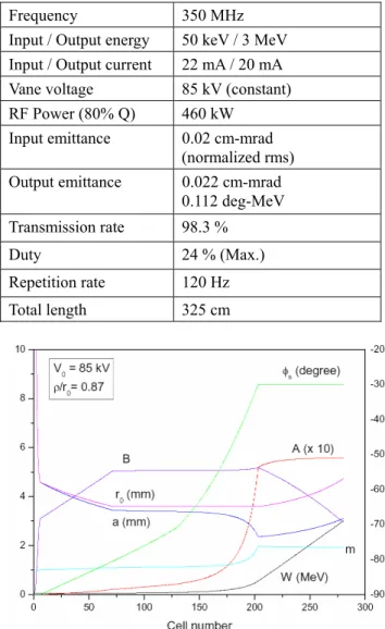
The parameters of PEFP 3MeV RFQ Upgrade is presented in Table 1. It is a 4 vane type with 4 sections, two segments, which are resonantly coupled for field stabilization. The radial matching section consists of 6 cells for the smooth matching of the RFQ input beam controlled by the last solenoid of LEBT. In order to maintain the RFQ length similar to that of old one, the shaper energy was determined as 86.5keV where the synchronous phase is linearly increasing. The ρ/r0 of
the vane is 0.87 and constant through the downstream which limits the surface electric field below the 1.8 Kirlpatrick. The fraction of the octupole components is less than 10% of the quadrupole value under those vane tip geometries.
The last cell of the RFQ is changed to adopt the transition cell to eliminate the energy uncertainty at the end of the RFQ and give the same physical length between horizontal and vertical vanes. Since it offers well defined ending region for RFQ, the additional fringe field region after the transition cell can be used for the transverse matching between RFQ and the downstream sections. The designed parameters of RFQ
upgrade are shown in Figure 1.
Table 1. PEFP 3MeV RFQ Parameters
Frequency 350 MHz
Input / Output energy 50 keV / 3 MeV Input / Output current 22 mA / 20 mA
Vane voltage 85 kV (constant)
RF Power (80% Q) 460 kW
Input emittance 0.02 cm-mrad
(normalized rms)
Output emittance 0.022 cm-mrad
0.112 deg-MeV
Transmission rate 98.3 %
Duty 24 % (Max.)
Repetition rate 120 Hz
Total length 325 cm
Figure 1. PEFP 3MeV RFQ Design Parameters: synchronous phase (φs), accelerating efficiency (A),
focusing efficiency (B), mid-cell aperture radius (r0),
minimum radius curvature (a), transverse curvature radius of the vane-tip (ρ), modulation (m), and particle energy (W).
The designed RFQ upgrade has some engineering features. The most serious problem of the old RFQ was inadequate tuning. That was its frequency was higher than the designed one and the field profile could not be adjusted because the measured field profile was beyond the limit which could be controlled by the tuners. Therefore, the brazing surface of the vane joint was changed from step geometry into flat one without any step in order to pre-brazing tuning. With those brazing
___________________________________________
* This work is supported by the 21C Frontier R&D program in the Ministry of Science and Technology of the Korean government
Transactions of the Korean Nuclear Society Autumn Meeting Busan, Korea, October 27-28, 2005
surface geometry, the minor vanes can be translated to adjust the resonant frequency, quadrupole and dipole field profile.
A number of geometries in radial matching section and fringe field region were considered to make smooth transition to the end of the vane, and the final geometry was determined through the machining of the mock up model.
The RF seals were changed from helicoflex into various ones. For the section to section joint, the main RF seal is the direct contact of the raised surface, and canted coil spring, which is located at the outside of the raised surface, is used as a backup. A 0.3mm thick tin is used for both RF and vacuum seals of tuner and pick up port. Also, canted coil springs were used for the RF seal of the high power RF coupler.
4. Fabrication
The PEFP 3MeV RFQ upgrade consists of 4 sections. The length of each section is about 80 cm long. A RFQ section is divided into 4 pieces, two are minor vanes, two are major vanes, which are joined together through brazing. The cavity material is OFHC copper. The RFQ vanes are machined with CNC machine. During the machining of the vane tips, ball end mill was used with 45degree angle to the axis of the vane. Cooling channels which are located at the vanes and the wall were machined with gun drill. The flange is joined into the cavity after the pre-brazing tuning. The flange is also OFHC copper supported stainless steel plate.
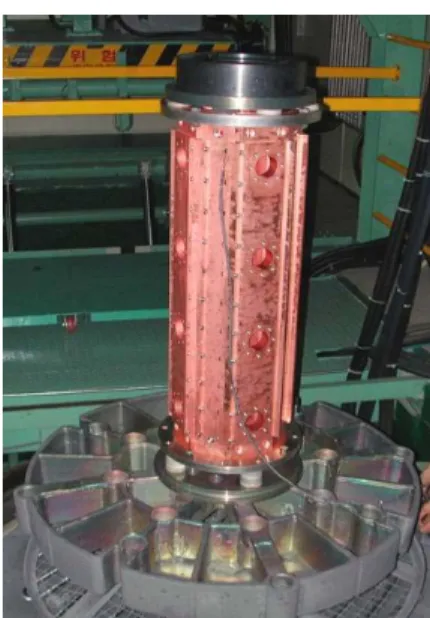
The 4 pieces of vanes are joined through brazing. The brazing filler metal is BAg-8 and the brazing temperature is 850 degree C. The required time for brazing is about 24 hours including warming and cooling time. The RFQ ready for brazing inside the furnace is shown in Figure 2.
The vacuum leak tests of each section with He leak detector after brazing showed that the leak rate of the brazed RFQ were less than 1E-9 torr l/s.
Until now, the RFQ upgrade has been installed and tuned. And high power test up to the designed field level of 1.8 Kirlpatrick with 80us pulse width, 1Hz repetition rate was completed without serious vacuum degradation [2]. The installed RFQ upgrade is shown in Figure 3.
5. Conclusion
A 3MeV RFQ upgrade has been developed at PEFP. It has features which are different from old one. They are to maintain constant voltage profile, to adopt a transition cell, to modify the brazing surface, to determine the smooth transition at the vane end region, and to adopt a new RF seal scheme. The fabrication of the RFQ upgrade with above features has been completed. And the installation, tuning and high power RF test up to design field level have been completed.
Figure 2. RFQ section prepared for brazing
Figure 3. Installed RFQ upgrade
6. Acknowledgement
This work is supported by Korea Ministry of Science and Technology.
7. REFERENCES
[1] H.J.Kwon, et al., “Preliminary Test Results of the PEFP 3MeV RFQ”, Proc. Of KAPRA & KPS/DPP Joint Workshop, 2004.
[2] Y.S.Cho, et al., “Test of the PEFP 3MeV RFQ Upgrade”, in these proceedings..