충전 프로파일 및 셀 밸런스 제어기술을 활용한 대용량 리튬이온 배터리
고속충전시스템 개발
Development of a Fast Charging System Utilizing Charge Profile and Cell
Balance Control Technology for Large Capacity Lithium-ion Batteries
가니 도가라 유나나a, 안재영b, 박찬원c*
Gani Dogara Yunanaa, Jae Young Ahnb, Chan Won Parkc*
a Topfield, Co., Ltd, (24461) #101, 882, Baksa-ro, Seo-myeon, Chuncheon-si, Gangwon-do, Republic of Korea b DTI Korea, Co., Ltd, #2308 ,National University Business School Building 2 (305B), 1, Kangwondaehak-gil,
Chuncheon-si, Gangwon-do, Republic of Korea
c Dept. of electrical and electronics engineering, (24341) #321, Engineering Dept. BLDG #1, 1, Kangwondaehak-gil,
Chuncheon-si, Gangwon-do, Republic of Korea
Received 29 August 2020; Revised 14 October 2020; Accepted 22 October 2020
Abstract
Lithium-ion cells have become the go-to energy source across all applications; however, dendritic growth remains an issue to tackle. While there have been various research conducted and possible solutions offered, there is yet to be one that efficiently rules out the problem without, however, introducing another. This paper seeks to present a fast charging method and system to which lithium-ion batteries are charged while maintaining their lifetime. In the proposed method, various lithium cells are charged under multiple profiles. The parameters of charge profiles that inflict damage to the cell’s electrodes are obtained and used as thresholds. Thus, during charging, voltage, current, and temperature are actively controlled under these thresholds. In this way, dendrite formation suppressed charging is achieved, and battery life is maintained. The fast-charging system designed, comprises of a 1.5kW charger, an inbuilt 600W battery pack, and an intelligent BMS with cell balancing technology. The system was also designed to respond to the aging of the battery to provide adequate threshold values. Among other tests conducted by KCTL, the cycle test result showed a capacity drop of only 0.68% after 500 cycles, thereby proving the life maintaining capability of the proposed method and system.
Keywords: Fast Charging, Charge Profile, Cell Balancing, Dendrite Formation, Lithium-ion Batteries, Lithium Plating
These dendrites can grow, penetrate through the separator and reach the cathode, thereby shorting the battery causing thermal runaway and, in the worst-case scenario, an explosion[4].
Recent studies have shown that dendrite formation occurs at different current levels and that these levels lower as the cells age[5]. Based on this information, this thesis presents a method and a fast-charging system designed to charge high capacity lithium-ion batteries, at a high C-rate while maintaining the battery life. In the proposed method, lithium-ion cells were charged under various charge profiles, and the conditions that bring about damage to the cell’s electrodes are obtained and used as a limit during fast charging.
1. Introduction
The high energy density yet lightweight characteristics of lithium-ion cells have made them the go-to source for energy supply in the growing e-mobility industry. However, unlike conventional vehicles, e-mobility vehicles suffer from limited range and long charging times due to the nature of these cells. Although many industries have adopted fast charging as a solution to these problems, fast charging exposes these cells to certain processes that damage the cell’s components, reducing its lifetime and making them unsafe for use[1, 2]. Amongst these processes is lithium plating[3], through which continuous charge and discharge at high C-rates, results in dendrite formation.
* Corresponding author. Tel.: +82-33-250-6294 fax: +82-33-259-5674
Because these limits lower with the age of the battery, the system was designed to respond accordingly. Furthermore, cell balancing technology was also incorporated to eliminate the dangers to which unbalanced cells bring about in a battery pack. In this way, the battery is charged using a dendrite suppressed charge profile, thereby maintaining its lifetime.
2. System Configuration
2.1 Hardware Components
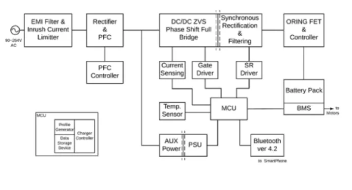
The fast-charging system designed includes a 1.5KW digital SMPS, a built-in 600W battery pack, and an Intelligent BMS to which the proposed charging method and cell balancing technology are implemented. The system components are shown in the diagram below.
Fig. 1 Block Diagram of Fast Charging System for Large Capacity Lithium-ion Batteries
Profile Generator: The profile generator consists of a data storage
device, linear predicting unit, measurement unit, and a correction unit. It is responsible for generating the threshold profile information (voltage, current, temperature), which will be used for dendrite suppressed charge profile determination. At the initial point, the threshold profile information is obtained through tests of lithium-ion cells under various charge profile conditions. However, as the battery ages, they are generated based on the predicted values.
Data Storage Device: A data storage device is needed for storing
information such as the initial/updated threshold profile information as well as data of the battery usage history over time. Thus a serial flash memory device is a part of the system. The user can obtain data from the storage device through Bluetooth.
Fast Charge Controller: As this system is aimed towards dendrite
formation suppressed charging, the fast charge controller refers to the threshold profile information saved in the data storage device and based on that creates a dendrite formation inhibiting charge profile. After the charge profile has been generated, it produces a control signal to which is used to control the charging circuit.
Charging Circuit: The charging circuit is a 1.5kW PSFB (Phase Shift
Full Bridge) Digital SMPS with ZVS (Zero Volt Switching) capabilities and an active PFC (Power Factor Correction) unit included. The charging circuit converts the external AC to DC, and having received the control signal from the charge controller, supplies the needed charging current or voltage based on the charging mode. The charging circuit provides an output of up to 60V, 24A.
Fig. 2 Digital SMPS Charging Circuit
Intelligent BMS: The BMS (Battery Management System) is made up of an LTC4368, LTC6811, a DC/DC Converter, current and temperature sensors, and a Bluetooth device. The LTC4368 provides over/under voltage as well as reverse protection. The LTC6811 monitors and acquires voltage values of each cell, as well as current and temperature data from the sensors and cell balancing related information, and sends it to the MCU (STM32F334R8 microcontroller) for analysis and control. The Bluetooth module makes it possible for the user to gain access to such information from their phones.
Battery Pack: The battery packs designed and tested in this project
include a 600W (50.4V/12A) and a 320W (37V/10A) battery pack. The 600W battery pack was made using the LG HG2 18650 cylindrical cells in a 14S4P configuration. The 320 battery pack was made using 3.7V 10Ah lifepo4 pouch type batteries in a 10S1P configuration.
2 – Phase Interleaved Active PFC Circuit Phase Shift Full Bridge DC/DC Converter Circuit
Fig. 3 Digital SMPS Circuit Board & Fast Charging System Parts
2.2 Software
Method of Charge/Discharge using Charge Profile
Threshold Value Setting Stage: In this stage, the charging condition,
which causes dendrite formation or damage to lithium batteries, is determined and saved to the data storage device as the threshold profile information. The initial threshold profile information is determined through the specification and testing of the lithium-ion batteries under various charge profile conditions.
As the battery ages, the profile generator continually collects and analyzes charge voltage, current, temperature data to determine temperature change (anode, cathode, and body) due to current/voltage change, change in charge efficiency due to temperature change, and decreased charge rate due to repetitive charge/discharge. The new threshold profile information to be updated in the data storage device is determined based on the linear predicted values of the initial threshold profile information and the battery’s current state. The threshold profile information may contain at least one or all of the following; voltage, current, time, and temperature.
Charge Profile Selection Stage: In this stage, the charge controller
refers to the threshold profile information in the data storage analyzes it and, based on the battery’s state, determines a dendrite formation suppressing charge profile. As the threshold profile information are parameters of a charge profile that brought about damage or reduced performance to the lithium cell, it is used by the charge controller as a limit/criterion (allowing a margin of error) to which charging is carried out without being exceeded. After the charge profile has been determined, a signal is generated to be used for controlling the charging circuit.
Charge Power Supply Stage: In this stage, the digital 1.5kW SMPS
is responsible for providing the power required for charging the battery.
As described in the charging circuit section, it takes a 220V AC input, and after undergoing filtering rectification and power factor correction, an unregulated high voltage (400V) is produced at the end of the PFC stage. At this point, the controller that controls the switching of the PSFB converter receives the signal from the charge controller and controls the converter to step down this high unregulated voltage down to the needed and regulated voltage. Based on the battery’s state of charge, it produces the current or voltage required for charging the battery pack. Also, a feedback circuit is also present, which compares the control signal and the output stage and compensates for any errors.
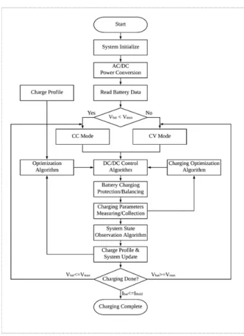
Battery Charging Stage: In the battery charging stage, the cell
characteristics are continuously measured and monitored by the BMS. This is to ensure that all cells are balanced, charging mode is changed based on the given conditions, and charging is ended at the given end conditions or in the case of emergency. And most of all, so that the charging conditions do not exceed the dendrite formation suppressing limit set by the charge controller. The flowchart below shows the process that takes place during charging.
3. Tests and Results
Multiple tests, including fast charge, temperature, and 500-cycle tests, were conducted to confirm the credibility of the proposed charging method and fast charge system.
Fast Charge Test and Result: For the fast charging test, the 600W
14S4P (50.4V/12A) battery pack was subject to charging with conditions as described in the table below. The goal of this test was to determine the charge profile of the battery pack as well as confirm full charge within 40~50 minutes.
Table 1 Fast Charge Test Charging Conditions Current (A) Voltage (V) Cut-off Condition Rest Time (min) Ambient Temp Charge (CC) 20 (1.6C) > 58.1V 30 (25±5)°C Charge (CV) 42 < 3A
This test was repeated eight times, and the results are as follows. The total charging time lasted an average of 45.5 minutes. The constant current mode took an average of 33.3 minutes and the constant voltage mode about 12.2 minutes.
Fig. 5 Voltage-Current Curve for Fast Charging Test
Temperature Test and Result: For the temperature test, the 600W
14S4P (50.4V/12A) battery pack was again used and was charged under the same conditions of the fast charge test. Temperature sensors were placed strategically in 4 different parts of the battery cell array. During charging, the temperature data of the four sensors as well as that of the environment in which the battery was charged (ambient temperature) were collected.
As shown in Fig. 6, during CC mode, the temperature gradually increased peaking at about 40.2°C and then fell off during the CV mode. Given the large battery capacity and high charging current used, we can conclude that charging was conducted within a safe region since the risk of thermal runaway starts at about 60°C and becomes very critical at 100°C.
Fig. 6 Temperature Curve showing Max Temperature
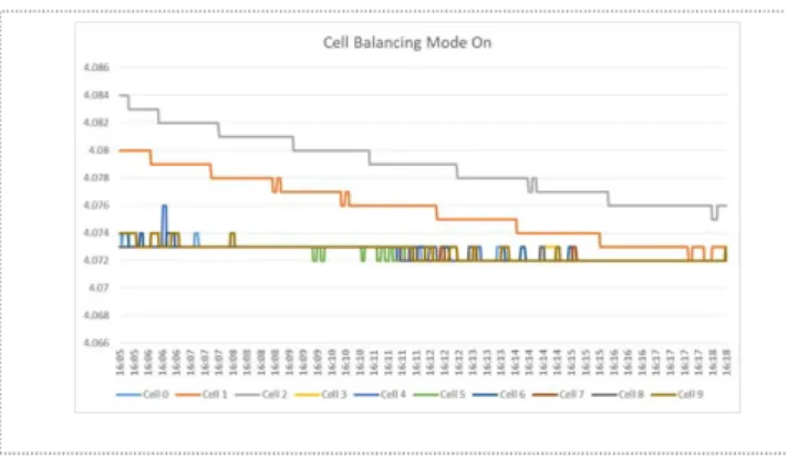
Cell Balancing Test and Result: The 320W 10S1P (37V/10A) battery
pack was used for this test. The BMS was designed to ensure that all cells in the battery are balanced or at least within the given 10mV range. Thus during charging, the cell balancing function is activated only when there is a cell deviation higher than 10mV.
Fig. 7 Diagram showing the balancing of an Imbalanced Cells
As shown in Fig. 7, Cell 8 (4.084V) is out of the 10mV range with the other cells by 11mV; thus, the cell balancing function is activated. Over 12 minutes, the imbalanced cell voltages were dissipated until they are balanced or within the 10mV cell deviation range. Cell balancing prevents the weaker cells from overcharge/deep discharge, thereby preventing exposure to cell degradation processes.
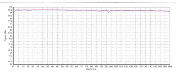
500 Cycle Test and Result: To test the battery life maintaining the
capability of the designed system under high charge/discharge rates, the test battery pack was subject to a 500 cycle charge/discharge cycle test. The goal of this test was to measure the amount of drop in capacity of the battery pack after being subject to 500 charge/discharge cycles. The 500-cycle test was conducted by KCTL on the 320W battery pack (10S1P, DC36V/10A) using the MACCOR series 4000 Battery and Cell Test equipment. The dendrite suppressing charging method was implemented, and the test was carried out as described below.
The test battery was charged at a 1.5C rate under a temperature of 25°. A 30-minute rest time was set between cycles and the capacity of the battery before each cycle was measured and recorded. This test took a total of three months. After 350 cycles, there was a 271-hour rest period, and the capacity at that time was 9400mAh. To determine the life maintenance capability of the battery pack, the initial capacity and capacity after 500 cycles were measured and, as shown in Table 2, was measured to be 99.32%.
Fig. 8 Battery Capacity over 500 charge/discharge Cycles
Table 2 500 charge/discharge Cycles Test Results Initial Capacity 9,460mAh Capacity after 500 Cycles 9,396mAh Efficiency after 500 Cycles 99.32%
Power Factor Measurement Test and Result: With the inclusion of a
PFC unit in the charger, a power factor measurement test was also conducted. This test was also carried out at KCTL using a power meter (WT210 Yokogawa) and a digital multimeter (15B+ Fluke). A Power Factor of 0.9877 was achieved. This means that most of the power is used to do work, and thus, losses generated due to inductive loads will have little impact on the system.
Power Efficiency Measurement Test and Result: KCTL also
conducted the power efficiency test. Two power meters (WT210 Yokogawa), a digital multimeter (15B+ Fluke), and a clamp-on AC/DC HITESTER (3285 HIOKI) was used.
Table 3 Power Efficiency Measurement Test Values Internal Input DC Voltage 388.29V Internal Input DC Current 2.95A
Output DC Voltage 53.60V Output DC Current 20.04A
The values, as shown in the table above, were obtained, and the Power Efficiency of the fast charging system was calculated to be 95.20%. This is important for the longevity and reliability of the charger and, thus, the battery as well.
Table 4 Tests & Results conducted by KCTL Summary Test Result
PFC Efficiency Test 0.9877 Power Efficiency Test 95.20%
Fast Charge Test 45.5 min
500-cycle Test 99.32%/500 cycles Cell Balancing Test < 10mV
Temperature < 45°C
4. Conclusion
In this paper, a fast-charging system for high capacity lithium-ion cells was designed, and the proposed charge/discharge method using charge profile and cell balancing technology was implemented. The aim was to build an efficient and reliable system to which fast charging can be carried out while protecting the battery pack from the dangers that conventional fast-charging methods used to bring about. The developed fast charging system after being subject to various tests at KCTL (Korea Compliance Testing Laboratories) obtained satisfactory results, as summarized in Table 4. Most importantly, a capacity loss of only 0.68% was achieved after 500 charge/discharge cycles at a 1.5C charge rate. Thus, we can conclude that through obtaining cell electrode damaging factors and using them as a limit for dendrite formation suppressed fast charging, a fast-charging yet battery life maintaining solution was realized.
References
[1] Tomaszewska, Anna Et al., 2019, Lithium-Ion Battery Fast Charging: A Review, eTransportation. 100011.
[2] Zhu, Gao‐Long Et al., 2019, Fast Charging Lithium Batteries: Recent Progress and Future Prospects, Small. 15. 1805389.
[3] T. Waldmann, B.-I. Hogg, Et al., 2018, Li plating as unwanted side reaction in commercial Li-ion cells-A Review, Power Sources, 384 (February), pp. 107-124.
[4] Birkl, Christoph Et al., 2017, Degradation diagnostics for lithium ion cells, Journal of Power Sources. 341. 373-386.
[5] Bai Peng, Li Ju, Brushett Fikile Et al., 2016, Transition of lithium growth mechanisms in liquid electrolytes, Energy Environ. Sci. 9. 3221-3229. [6] Li Linlin, Li Siyuan, Lu Yingying, 2018, Suppression of dendritic lithium
growth in lithium metal-based batteries, Chemical Communications. 54. [7] Majid Nik, Hafiz S, Arianto S, Et al., 2017, Analysis of effective pulse current
charging method for lithium ion battery, Journal of Physics: Conference Series. 817.
[8] Weixiang Shen, Thanh Tu Vo, Et al., 2012, Charging algorithms of lithium-ion batteries: an overview, 7th IEEE conference on industrial electronics and applications (ICIEA), IEEE, pp. 1567-1572.
[9] X.-G. Yang, G. Zhang, S. Ge, Et al., 2018, Fast charging of lithium-ion batteries at all temperatures, Proc. Natl. Acad. Sci. U.S.A, 115 (28), pp. 7266-7271. [10] J. Vetter, P. Novák, Et al., 2005, Ageing mechanisms in lithium-ion batteries,