Comparison of a Supporting Ability of Spacer Grid Springs under Fretting Wear Condition
in Room Temperature Air
Young-Ho Lee†, Hyung-Kyu Kim
Advanced LWR Fuel Development, Korea Atomic Energy Research Institute [email protected]
1. Introduction
One of the most important roles of a spacer grid spring/dimple in the nuclear fuel assemblies is to support the fuel rod at the specific positions. Otherwise, fuel rod could be arbitrary swayed or vibrated due to a flow-induced vibration (FIV). At this time, fretting wear mode could be altered from sliding wear to impact/sliding wear. Generally, impact/sliding wear between fuel rod and spacer grid spring/dimple could be generated due to the degradation of the supports caused by irradiation and thermal effects after long operation period. If an excess wear, however, happens in the depth direction of fuel rod during initial operating period, a supporting ability of a spacer grid spring can be degraded because a fuel rod was only supported by spring force. So, the objectives of this study is to examine the variation of contact (normal)/shear force under fretting wear condition and to evaluate the wear resistance based on a supporting ability of a spacer grid spring.
2. Experimental Procedure
2.1 Specimen
Two types of grid springs are used in this study and marked as spring A and B. Spring A is designed to have a concave contour. It was intended that these springs could wrap around the tube specimen in a transverse direction of the contact region. While spring B has a convex contour, so this spring has a line contact with the tube specimen in its axial direction.
2.2 Test Condition
All wear tests were carried out up to 107 cycles under
the same test condition such as a normal load of 10 N, a peak-to-valley amplitude of 100 µm, and at a frequency of 30 Hz in room temperature air. All the measured data (normal and shear load, slip amplitude, etc.) are monitored and recorded in a PC on a real time basis. 2.3 Wear Evaluation
After the wear experiment, wear volume/depth and worn area of the fuel rod specimen were measured and calculated by using a 2-D surface roughness tester and an optical microscope, respectively. Also, spring
characteristic tests (P-δ curve) were performed in order to evaluate the spring stiffness of each tested spring.
3. Results and Discussion
3.1 Variation of Contact and Shear Force
Fig. 1 shows the variation of contact force with increasing fretting cycles. The contact (normal, Ln)
force was considerably decreased in the spring A condition while the spring B condition did not have a significant force drop up to 107 cycles (about 30%
decrease at the spring B condition). This result indicated that a supporting ability of the spring B is superior to that of the spring A if initial contact force and fretting wear condition are the same. From the results of shear force range (∆Ls), spring A condition
also shows a rapid drop at initial fretting cycles when compared with spring B condition.
Table. 1 Fretting wear results and spring characteristics Spring A B Volume [mm3] 0.166 0.112 Depth (D) [µm] 65.5 52.8 Area [mm2] 6.62 7.63 Estimated D [µm] 20.5 20.2 Stiffness [N/mm] 211 135
Figure 1. Variation of contact (normal) force and shear range with increasing fretting cycles; Note that two black arrows indicate the contact force fluctuation.
Contact and shear force drop in the spring A condition could be explained by using spring stiffness. If the spacer grid spring has a relatively high stiffness
Transactions of the Korean Nuclear Society Autumn Meeting Busan, Korea, October 27-28, 2005
value, elastically deformed displacement under a specific contact force is smaller. In this test, as the spring specimen was firmly fixed during the fretting wear test, contact force drop is closely related to the depth increase both the fuel rod and the spring specimens. If it is assumed that depth was evenly increase at both specimens and there is not enough time for wear debris to remain in contacting surfaces, it is possible to estimate the wear depth by referring to the contact force drop and spring stiffness. However, the estimated results were much different with the measured ones as listed in Table 1. Hence, it is not enough to explain the above force drop by using the spring stiffness only.
3.2 Contact Force and Wear Debris Layer
As shown in Fig. 1, the contact normal and shear forces were decreased with increasing fretting cycles in both spring A and B conditions even though there is a great difference of the amount of the force drop. However, those are not continuously decreased as marked with arrows about 1.0 x 10⁶ and 3.6 x 10⁶
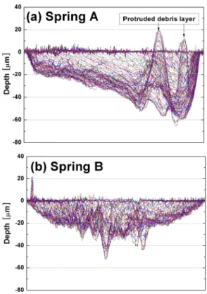
cycles, especially, in the spring A condition. It is thought that this contact force fluctuation was affected by the wear debris behavior. Fig. 2 shows the 2-D profiles of the worn area after wear volume/depth measurements.
Figure 2. Measurement results of worn surface profile; Note that a protruded debris layer was well-developed in the spring A condition.
It is apparent that protruded wear debris layers were well-developed in the worn area in the case of spring A.
Main causes of this result could be summarized as followings; firstly, the contact length of spring A condition is limited about 4.2 ~ 4.4 mm, which is independent of the applied normal load, frequency, etc. because fretting wear always initiates at the both ends of spring A [1]. Secondly, the debris falls down inside the worn surface as it is removed from the contact surface of spring A because fuel rod was reciprocated to the axial direction. However, wear was locally occurred in both ends of the spring A during the initial fretting cycles. So, wear debris could not be easily ejected downwards. Finally, some of remained wear debris could be accumulated and build up to form a load-bearing layer [2] under the center region due to the gravity. In spring B condition, however, the contact length was closely related to the contacting force. Also, wear could initiate in the center region and wear debris could be easily removed to depth direction when compared with spring A condition. Consequently, higher wear volume and maximum wear depth in spring A condition are due to both the seesaw motion of the fuel rod on the protruded debris layer and the third body abrasion between the worn surfaces.
4. Conclusion
In order to examine the variation of contact (normal)/shear force under fretting wear condition, fretting wear tests have been performed using two types of grid springs in room temperature air. The results indicated that a supporting ability of the spring B is superior to that of the spring A in this test condition. Also, it is difficult to explain the behavior of the force drop by referring to the spring stiffness only. Higher wear volume and maximum wear depth in the concave shape spring condition are caused by both the seesaw motion of the fuel rod on the protruded debris layer and the third body abrasion between the worn surfaces.
ACKNOWLEDGEMENTS
This study has been carried out under the Nuclear R&D Program by Ministry of Science and Technology in Korea.
REFERENCES
[1] Y.-H. Lee, H.-K. Kim, Y.-H. Jung, Relationship between spring shapes and the ratio of wear volume to the worn area in nuclear fuel fretting, KSTLE International Journal Vol.4 (2003) pp. 31-36.
[2] H.-K. Kim, Y.-H. Lee, Influence of contact shape and supporting condition on tube fretting wear, Wear 255 (2003) 1183-1197.