보구조물의 모드변형에너지기반 손상 검색: 3가지 타입 센서의 비교
Modal Strain Energy-based Damage Detection in Beam Structures using
Three Different Sensor Types
Ho Duc Duy*∙홍동수**∙김 정 태*** Ho, Duc-Duy∙Hong, Dong-Soo∙Kim, Jeong-Tae
1)
Abstract
This study deals with damage detection in beam structure by using modal strain energy-based technique with three different sensor types: accelerometer, lead zirconate titanate (PZT) piezoelectric sensor and electrical strain gage. First, the use of direct piezoelectric effect of PZT sensor for dynamic strain response are presented. Next, a modal strain energy-based damage detection method is outlined. For validation, forced vibration tests are carried out on lab-scale aluminum cantilever beam. The dynamic responses are measured for several damage scenarios. Based on damage localization results, the performance of three different sensor types is evaluated.
Keywords : modal strain energy, damage detection, cantilever beam, PZT, electrical strain gage
1. Introduction
Structural health monitoring (SHM) has become increasingly important for many fields such as aerospace engineering and civil engineering in recent years. In order to monitoring the integrity of structures, many kind of smart sensors and damage detection techniques was employed (Liang et al., 1996; Sirohi and Chopra, 2000; Farrar, 2001; Kim et al., 2003). Consequently, there exists an issue that how to select the cost-effective and reliable system for SHM purpose. The main objective of this study is to survey and evaluate the performance of three different sensor types (i.e., accelerometer, lead zirconate titanate (PZT) piezoelectric sensor and electrical strain gage) for modal strain energy (MSE)-based damage detection in beam structures. In order to obtain the objective, forced vibration tests is carried out on lab-scale aluminum cantilever beam for which dynamic responses are measured by three sensor types and two damage scenarios.
2. Dynamic Strain Response from PZT's Direct Piezoelectric Effect
Piezoelectric materials are widely used as both sensors (direct effect) and actuators (inverse effect) for SHM applications (Liang et al., 1996; Sirohi and Chopra, 2000). For example, PZT material can be employed as a sensor for dynamic strain measurement. Strain is measured in terms of the charge generated by PZT sensor as a result of direct effect. When a PZT sensor is mechanically strained, an electrical field is produced (Fig. 1). The constitutive relations of the PZT strain for 1D interaction:
* * 학생회원∙부경대학교 해양공학과 박사과정 [email protected]
*** 학생회원∙부경대학교 해양공학과 박사과정 [email protected]
*** 정회원∙부경대학교 해양공학과 교수 [email protected]
(1)
(2) 1 3 2 1 3 2 Host Structure ε1 ε1 PZT Sensor ~ E3Fig. 1 1-D PZT-structure interaction in direct piezoelectric effect where
is electric displacement; is the dielectric constant of piezoelectric wafer;
is applied external electric field in direction 3; is the piezoelectric coupling constant; is stress in direction 1; is strain in direction 1; is the complex Young’s modulus of the zero-electric field. If the PZT sensor bonded on surface of host structure is desired to be used as sensor only, without external electric field across its terminals, the strain in the PZT sensor can be expressed in terms of the voltage measured across its terminals as (Sirohi and Chopra, 2000):
(3)where
is output voltage across the terminals of the PZT sensor; is thickness of PZT sensor. FromEq. (3), the dynamic strain is determined from the output voltage which is easily measured directly.
3. Modal Strain Energy-based Damage Detection Method
Modal strain energy (MSE) is one of damage sensitive features using mode shape curvature. Kim et al. (2003) proposed an MSE-based damage index method by measuring the fractional change in MSE. The MSE-based damage index is defined as
(4) where and
represent the MSE-based damage index and material stiffness for the jth member, respectively;
involves only geometric quantities,
is ith modal stiffness; and the symbol (*) denotes the damaged state. The damage indices are also normalized according to the standard rule as
(5) where and represent, respectively, the mean and standard deviation of the collection of values. Then, the damage is localized from the statistical hypothesis tests (Kim et al., 2003).4. Experimental Validation
4.1. Forced Vibration Test on Lab-scale Aluminum Cantilever Beam
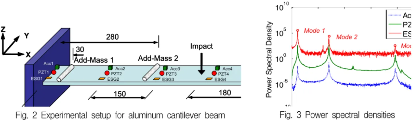
Dynamic tests were performed on a lab-scale 600x60x10 mm aluminum cantilever beam as shown in Fig. 2. Five sensor locations were arranged along the beam with a constant interval 150 mm and the impact force was applied at a location 180 mm distanced from the free end. Table 1 gives the information about three measurement system for acceleration from accelerometers, dynamic strain from
PZT sensors and dynamic strain from electrical strain gages. The cost for measuring dynamic strain from PZT sensors is lowest (i.e., about 12.5% cost for acceleration measurement).
Table 1 Measurement system
No. Acceleration Dynamic strain (PZT sensor) Dynamic strain (Strain gage)
1 Dytran 3101BG accelerometer FT-20T-3.6A1 PZT sensor TML FLA-5-11-1L strain gage
2 NI-6036E DAQ card NI-6036E DAQ card TML SB120B bridge box
3 BNC-2090 terminal block BNC-2090 terminal block Kyowa EDX-100A universal recorder
4 PCB-481A03 signal conditional Laptop Laptop
5 Laptop
Total cost 16,800 USD 2,100 USD 14,300 USD
Dynamic responses were measured in vertical direction with sampling frequency of 1 kHz. Frequency domain decomposition (FDD) method (Brincker et al., 2001) was employed to extract frequency responses and modal parameters. To simulate the damage, a 0.25 kg mass was added on the beam at 30 mm (i.e., Add-Mass 1) or 280 mm (i.e., Add-Mass 2) from the fixed end.
Impact X Z Y Acc1 ESG1 150 180 PZT1 Acc2 ESG2 PZT2 Acc3 ESG3 PZT3 Acc4 ESG4 PZT4 30 Add-Mass 1 Add-Mass 2 280 Impact X Z Y Acc1 ESG1 150 180 PZT1 Acc2 ESG2 PZT2 Acc3 ESG3 PZT3 Acc4 ESG4 PZT4 30 Add-Mass 1 Add-Mass 2 280
Fig. 2 Experimental setup for aluminum cantilever beam
10 10-5 100 105 1010 Po w er Sp ec tr al D en sit y AcPZ ES Mode 1 Mode 2 Mod
Fig. 3 Power spectral densities Figures 3 and 4 show the power spectral densities and mode shape curvatures for first three bending modes, respectively. A good match between three sensor types were obtained. Frequency response from strain gages contains high noise level in comparison with accelerometers and PZT sensors. It should be noted that mode shape curvatures are obtained directly in case of using PZT sensors and strain gages. For accelerometers, one more step is required to determine mode shape curvatures from mode shapes.
-0.8 -0.6 -0.4 -0.2 0 M odal A m pli tude A P E -0.6 -0.4 -0.2 0 0.2 0.4 0.6 M odal A m plit ude Acc PZT ESG -0.6 -0.4 -0.2 0 0.2 0.4 0.6 M odal A m plit ude A P E
(a) Mode 1 (b) Mode 2 (c) Mode 3
Fig. 4 Mode shape curvatures 4.2. MSE-based Damage Localization Results
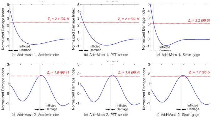
As described in section 3, damage localization index is calculated from the fractional change in MSE between undamage and damage case. Figure 5 shows the MSE-based damage indices for two damage cases (i.e., Add-Mass 1 and Add-Mass 2) by using three different sensor types (i.e., accelerometer, PZT
sensor and strain gage). It is observed that the damage location can be detect with high confident level 95.54%-99.18% corresponding to normalized damage index 1.7-2.4. Electrical strain gage has lower confident level than accelerometer and PZT sensor. For cantilever beam, it is easier to detect the damage near fixed end than mid-span location.
-1 0 1 2 3 4 5 Nor m aliz ed Dam age I ndex Acc Inflicted Damage Zo= 2.4 (99.18 -1 0 1 2 3 4 5 Nor m aliz ed Dam age I ndex 5 PZTs Inflicted Damage Zo= 2.4 (99.18 -1 0 1 2 3 4 5 Nor m aliz ed Dam age I ndex Inflicted Damage Zo= 2.2 (98.61
(a) Add-Mass 1: Accelerometer (b) Add-Mass 1: PZT sensor (c) Add-Mass 1: Strain gage
-1 0 1 2 3 Nor m aliz ed Dam age I ndex Acc Inflicted Damage Zo= 1.8 (96.41 -1 0 1 2 3 Nor m aliz ed Dam age I ndex 5 PZTs Inflicted Damage Zo= 1.8 (96.41 -1 0 1 2 3 Nor m ali zed Dam age I ndex Inflicted Damage Zo= 1.7 (95.54
(d) Add-Mass 2: Accelerometer (e) Add-Mass 2: PZT sensor (f) Add-Mass 2: Strain gage
Fig. 5 MSE-based damage indices
5. Conclusions
In this study, the performance of accelerometer, PZT sensor and electrical strain gage for MSE-based damage detection in aluminum cantilever beam was evaluated. Among them, PZT sensor promises as a smart sensor with low cost and good performance. Especially, PZT sensors can be dual utilized for dynamic strain-impedance-based global and local SHM applications.
Acknowledgement
This study was supported by the Second Stage Brain Korea 21 (BK21) Program of Korean Government.
References
Brincker, R., Zhang. L., Andersen, P. (2001) Modal identification of output-only using frequency domain decomposition, Smart Materials and Structures, 10, pp.441-445.
Farrar, C.R. (2001) Historical overview of structural health monitoring, Lecture Notes on Structural
Health Monitoring Using Statistical Pattern Recognition, Los Alamos Dynamics, Los Alamos, NM.
Kim, J.T., Ryu, Y.S., Cho, H.M., Stubbs, N. (2003) Damage identification in beam-type structures: frequency-based method vs mode-shape-based method, Engineering Structures, 25, pp.57-67.
Liang, C., Sun, F.P., Rogers, C.A. (1996) Electro-mechanical impedance modeling of active material systems, Smart Materials and Structures, 5(2), pp.171-186.
Sirohi, J., Chopra, I. (2000) Fundamental understanding of piezoelectric strain sensors, Journal of
Intelligent Material Systems and Structures, 11, pp.246-257.