300-MHz-repetition-rate, all-fiber, femtosecond
laser mode-locked by planar lightwave
circuit-based saturable absorber
Chur Kim,1 Dohyun Kim,1 YeonJoon Cheong,1 Dohyeon Kwon,1 Sun Young Choi,2 Hwanseong Jeong,2 Sang Jun Cha,3 Jeong-Woo Lee,4 Dong-Il Yeom,2 Fabian
Rotermund,2 and Jungwon Kim1,*
1School of Mechanical and Aerospace Engineering, Korea Advanced Institute of Science and Technology (KAIST),
Daejeon 305-701, South Korea
2Department of Energy Systems Research & Department of Physics, Ajou University, Suwon 443-749, South Korea 3FiberPro Inc., Daejeon 305-343, South Korea
4FM Solution Inc., Daegu 711-873, South Korea *jungwon.kim@kaist.ac.kr
Abstract: We show the implementation of fiber-pigtailed,
evanescent-field-interacting, single-walled carbon nanotube (CNT)-based saturable absorbers (SAs) using standard planar lightwave circuit (PLC) fabrication processes. The implemented PLC-CNT-SA device is employed to realize self-starting, high-repetition-rate, all-fiber ring oscillators at telecommunication wavelength. We demonstrate all-fiber Er ring lasers operating at 303-MHz (soliton regime) and 274-MHz (stretched-pulse regime) repetition-rates. The 303-MHz (274-MHz) laser centered at 1555 nm (1550 nm) provides 7.5 nm (19 nm) spectral bandwidth. After extra-cavity amplilfication, the amplified pulse train of the 303-MHz (274-MHz) laser delivers 209 fs (178 fs) pulses. To our knowledge, this corresponds to the highest repetition-rates achieved for femtosecond lasers employing evanescent-field-interacting SAs. The demonstrated SA fabrication method, which is based on well-established PLC processes, also shows a potential way for mass-producible and lower-cost waveguide-type SA devices suitable for all-fiber and waveguide lasers.
©2015 Optical Society of America
OCIS codes: (140.3510) Lasers, fiber; (230.0230) Optical devices; (320.7090) Ultrafast lasers. References and links
1. B. Bernhardt, A. Ozawa, P. Jacquet, M. Jacquey, Y. Kobayashi, T. Udem, R. Holzwarth, G. Guelachvili, T. W. Hänsch, and N. Picqué, “Cavity-enhanced dual-comb spectroscopy,” Nat. Photonics 4(1), 55–57 (2010). 2. F. Yoshino, L. Shah, M. Fermann, A. Arai, and Y. Uehara, “Micromachining with a high repeptition rate
femtosecond fiber laser,” J. Laser Micro. Nanoeng. 3(3), 157–162 (2008).
3. L. Karvonen, A. Säynätjoki, S. Mehravar, R. D. Rodriguez, S. Hartmann, D. R. T. Zahn, S. Honkanen, R. A. Norwood, N. Peyghambarian, K. Kieu, H. Lipsanen, and J. Riikonen, “Investigation of second- and third-harmonic generation in few-layer gallium selenide by multiphoton microscopy,” Sci. Rep. 5, 10334 (2015). 4. U. Keller, K. J. Weingarten, F. X. Kärtner, D. Kopf, B. Braun, I. D. Jung, R. Fluck, C. Honninger, N. Matuschek,
and J. Aus der Au, “Semiconductor saturable absorber mirrors (SESAM’s) for femtosecond to nanosecond pulse generation in solid-state lasers,” IEEE J. Sel. Top. Quantum Electron. 2(3), 435–453 (1996).
5. O. Okhotnikov, A. Grudinin, and M. Pessa, “Ultra-fast fibre laser systems based on SESAM technology: new horizons and applications,” New J. Phys. 6, 177 (2004).
6. Y.-W. Song, S. Yamashita, C. S. Goh, and S. Y. Set, “Carbon nanotube mode lockers with enhanced nonlinearity via evanescent field interaction in D-shaped fibers,” Opt. Lett. 32(2), 148–150 (2007).
7. K. Kieu and M. Mansuripur, “Femtosecond laser pulse generation with a fiber taper embedded in carbon nanotube/polymer composite,” Opt. Lett. 32(15), 2242–2244 (2007).
8. D. Popa, Z. Sun, T. Hasan, W. B. Cho, F. Wang, F. Torrisi, and A. C. Ferrari, “74-fs nanotube-mode-locked fiber laser,” Appl. Phys. Lett. 101(15), 153107 (2012).
9. D. Popa, Z. Sun, F. Torrisi, T. Hasan, F. Wang, and A. C. Ferrari, “Sub 200 fs pulse generation from a graphene mode-locked fiber laser,” Appl. Phys. Lett. 97(20), 203106 (2010).
10. E. J. Lee, S. Y. Choi, H. Jeong, N. H. Park, W. Yim, M. H. Kim, J.-K. Park, S. Son, S. Bae, S. J. Kim, K. Lee, Y. H. Ahn, K. J. Ahn, B. H. Hong, J.-Y. Park, F. Rotermund, and D.-I. Yeom, “Active control of all-fibre graphene devices with electrical gating,” Nat. Commun. 6, 6851 (2015).
11. J. Lee, J. Koo, Y. M. Jhon, and J. H. Lee, “A femtosecond pulse erbium fiber laser incorporating a saturable absorber based on bulk-structured Bi2Te3 topological insulator,” Opt. Express 22(5), 6165–6173 (2014). 12. J. Sotor, G. Sobon, K. Grodecki, and K. M. Abramski, “Mode-locked erbium-doped fiber laser based on evanescent field interaction with Sb2Te3 topological insulator,” Appl. Phys. Lett. 104(25), 251112 (2014). 13. H. Jeong, S. Y. Choi, F. Rotermund, Y.-H. Cha, D.-Y. Jeong, and D.-I. Yeom, “All-fiber mode-locked laser
oscillator with pulse energy of 34 nJ using a single-walled carbon nanotube saturable absorber,” Opt. Express 22(19), 22667–22672 (2014).
14. S. Y. Ryu, K.-S. Kim, J. Kim, and S. Kim, “Degradation of optical properties of a film-type single-wall carbon nanotubes saturable absorber (SWNT-SA) with an Er-doped all-fiber laser,” Opt. Express 20(12), 12966–12974 (2012).
15. K. Kashiwagi, S. Yamashita, Y. Nasu, H. Yaguchi, C. S. Goh, and S. Y. Set, “Planar waveguide-type saturable absorber based on carbon nanotubes,” Appl. Phys. Lett. 89(8), 081125 (2006).
16. H. Jeong, S. Y. Choi, E. I. Jeong, S. J. Cha, F. Rotermund, and D.-I. Yeom, “Ultrafast mode-locked fiber laser using a waveguide-type saturable absorber based on single-walled carbon nanotubes,” Appl. Phys. Express 6(5), 052705 (2013).
17. H. Takahashi, “Planar lightwave circuit devices for optical communication: present and future,” Proc. SPIE 5246, 520–531 (2003).
18. J. W. Lee, S. S. Kim, B.-T. Lee, and J. H. Moon, “Ge-doped SiO2 glass films prepared by plasma enhanced chemical vapor deposition for planar waveguides,” Appl. Surf. Sci. 228(1-4), 271–276 (2004).
19. W. B. Cho, J. H. Yim, S. Y. Choi, S. Lee, A. Schmidt, G. Steinmeyer, U. Griebner, V. Petrov, D.-I. Yeom, K. Kim, and F. Rotermund, “Boosting the non linear optical response of carbon nanotube saturable absorbers for broadband mode-locking of bulk lasers,” Adv. Funct. Mater. 20(12), 1937–1943 (2010).
20. J. Boguslawski, G. Sobon, R. Zybala, and J. Sotor, “Dissipative soliton generation in Er-doped fiber laser mode-locked by Sb2Te3 topological insulator,” Opt. Lett. 40(12), 2786–2789 (2015).
21. G. C. Valley, “Photonic analog-to-digital converters,” Opt. Express 15(5), 1955–1982 (2007).
22. S. T. Cundiff and A. M. Weiner, “Optical arbitrary waveform generation,” Nat. Photonics 4(11), 760–766 (2010).
23. J. Ye and S. T. Cundiff, Femtosecond Optical Frequency Comb Principle, Operation and Applications (Springer, 2005).
24. K. Jung, J. Shin, J. Kang, S. Hunziker, C. K. Min, and J. Kim, “Frequency comb-based microwave transfer over fiber with 7x10⁻¹⁹ instability using fiber-loop optical-microwave phase detectors,” Opt. Lett. 39(6), 1577–1580 (2014).
25. J. Zhang, F. Niu, X. Chen, X. Gao, Y. Liu, A. Wang, and Z. Zhang, “464 MHz repetition rate erbium doped soliton fiber laser,” in Conference on Lasers and Electro-Optics (CLEO): 2014, OSA Technical Digest (online) (Optical Society of America, 2014), paper SW3E.1.
26. X. Wei, S. Xu, H. Huang, M. Peng, and Z. Yang, “Compact all-fiber ring femtosecond laser with high fundamental repetition rate,” Opt. Express 20(22), 24607–24613 (2012).
27. H. Byun, D. Pudo, J. Chen, E. P. Ippen, and F. X. Kärtner, “High-repetition-rate, 491 MHz, femtosecond fiber laser with low timing jitter,” Opt. Lett. 33(19), 2221–2223 (2008).
28. J. W. Nicholson and D. J. DiGiovanni, “High-repetition-frequency low-noise fiber ring lasers mode-locked with carbon nanotubes,” IEEE Photonics Technol. Lett. 20(24), 2123–2125 (2008).
29. K. Wu, X. Zhang, J. Wang, and J. Chen, “463-MHz fundamental mode-locked fiber laser based on few-layer MoS2 saturable absorber,” Opt. Lett. 40(7), 1374–1377 (2015).
30. J. W. Nicholson, J. Jasapara, W. Rudolph, F. G. Omenetto, and A. J. Taylor, “Full-field characterization of femtosecond pulses by spectrum and cross-correlation measurements,” Opt. Lett. 24(23), 1774–1776 (1999). 31. K. Tamura and M. Nakazawa, “Pulse compression by nonlinear pulse evolution with reduced optical wave
breaking in erbium-doped fiber amplifiers,” Opt. Lett. 21(1), 68–70 (1996).
32. C. Kim, S. Bae, K. Kieu, and J. Kim, “Sub-femtosecond timing jitter, all-fiber, CNT-mode-locked Er-laser at telecom wavelength,” Opt. Express 21(22), 26533–26541 (2013).
1. Introduction
Passively mode-locked fiber lasers have been recognized as a reliable and practical source generating femtosecond optical pulses, due to their alignment-free operation, efficient heat dissipation, compactness, and low cost. They have been actively used for a number of applications ranging from frequency comb spectroscopy [1] through micro-machining [2] to multiphoton microscopy [3]. For long-term stability and turn-key operation of mode-locked fiber lasers, the implementation of real saturable absorbers inside the oscillator is highly desirable. For this, semiconductor saturable absorber mirrors (SESAMs) [4] have been widely employed in mode-locked fiber lasers [5].
More recently, new types of saturable absorber (SA) devices with lower manufacturing cost and easier fabrication methods have been demonstrated and further applied to fiber lasers [6–16]. These SA devices are based on saturable absorption materials such as single-walled carbon nanotubes (CNTs) [6–8], graphene [9,10], and topological insulators [11,12]. Such new SA materials also enable evanescent-field-interaction-type implementation of SA devices [6,7,10–13,15,16]. Evanescent-field-interaction structure has recently attracted great interest due to their much reduced thermal damage problems compared to ferrule-type [8,9,14] or mirror-type [5] SA structures. For example, fiber lasers mode-locked by side-polished fiber-based CNT-SA devices could achieve >34 nJ intra-cavity pulse energy with damage threshold of 97 mJ/cm2 [13], which is 30 dB higher than that of ferrule-type CNT-SA device reported in
[14]. Evanescent-field-intereacting SAs have been implemented by coating the SA films on specially fabricated fibers (such as side-polished fibers [6] and tapered fibers [7]) or on waveguide devices [15,16].
In the last decade, planar lightwave circuit (PLC) technology [17] has been well established to manufacture passive silica waveguide devices, such as arrayed waveguide gratings (AWGs) and 1 × N splitters, for fiber-optic communication industry with low-cost and high-volume manufacturability. The implementation of evanescent-field-interacting SA functionality on planar waveguides by PLC fabrication process may lead to low-cost and mass-producible manufacturing of SA devices applicable for femtosecond all-fiber and waveguide lasers.
In this paper, we employ the standard PLC fabrication processes to implement evanescent-field-interacting CNT-SA devices. The manufactured PLC-CNT-SA is further fiber-pigtailed by bonding fiber array blocks (FABs) at both input and output ports, which enables its application for all-fiber lasers. As the first application, we employ this fiber-pigtailed PLC-CNT-SA device in high-repetition-rate lasers, where thermal damage and degradation issues of SAs is crucial for long-term stable operation. We demonstrate 303-MHz (soliton regime) and 274-MHz (stretched-pulse regime) repetition-rate, self-starting, all-fiber Er ring lasers. The 303-MHz (274-MHz) laser centered at 1555 nm (1550 nm) provides 7.5 nm (19 nm) full-width at half-maximum (FWHM) spectral bandfull-width. After the extra-cavity Er-doped fiber amplifier (EDFA), the amplified average power amounts to 76 mW (71 mW) at 303 MHz (274 MHz) and the FWHM pulse duration is measured to be 209 fs (178 fs). To our knowledge, this result corresponds to the highest repetition-rate achieved for femtosecond fiber lasers employing evanescent-field-interacting SAs.
2. PLC-based SA device fabrication and characterization
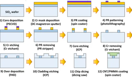
The PLC-CNT-SA demonstrated in this work is made by standard PLC fabrication processes [18]. Figure 1 summarizes the entire fabrication process of the PLC-CNT-SA chip. First, Ge-doped SiO2 film is deposited onto the prepared SiO2 wafer by plasma enhanced chemical
vapor deposition (Step 1). The process gas, consisting of SiH4 (99.999%) 17 sccm, N2O
(99.999%) 2000 sccm and GeH4 (10% diluted in Ar) 10.5 sccm, is used to deposit 6-μm-thick
Ge-doped SiO2 film with a refractive index 0.36% or 0.45% higher than that of SiO2 wafer.
The Ge-doped SiO2 film is then thermally annealed in N2 atmosphere at 1100°C for 12 hours.
After that, Cr mask layer is patterned through a series of processes (Steps 2-6): PR spin coating, photolithography, and 1-minute wet etching process by using Cr etchant. In Step 7, core layer (Ge-doped SiO2 layer) is etched by inductively coupled plasma (ICP) etching
process. After the formation of rectangular waveguide structures, Cr mask layer is removed by using Cr etchant (Step 8). Over-cladding layer (SiO2 layer) is subsequently deposited over
core layer by frame hydrolysis deposition (FHD) process (Step 9). Subsequently, it is thermally annealed for 12 hours for densification. Note that Steps 1-9 follow the standard PLC processes also used for manufacturing commercial silica waveguide devices such as AWGs and couplers.
In Step 10, over-cladding is selectively etched until the top surface of core layer is exposed to air, so that the evanescent field can effectively interact with the saturable absorption materials (which will be coated on the over-cladding layer in Step 12). After selectively etching over-cladding, fabricated silica wafer is diced into individual PLC chips (Step 11). When using standard 6” wafer, ~100 chips with 3 cm×0.35 cm size can be manufactured. Finally, a saturable absorber layer is coated on the PLC chips. In this work, we used single-walled CNT/PMMA composite, which has been well developed as effective saturable absorber in last years. Detailed procedures for the preparation of CNT/PMMA composite used can be found in [19]. The prepared CNT/PMMA composite is spin-coated on top of the fabricated PLC-SA chips with few hundreds nm thickness depending on the spin speed (Step 12). The coated CNT/PMMA layer thickness can be adjusted from 500 nm up to ~5 μm by repeating the spin-coating procedures.
Although CNT-PMMA composite is used as the SA material in this work, other film type SAs such as graphene and topological insulators can be used as well. For example, a pulsed magnetron sputtering method recently demonstrated in [20] can be used to deposit Sb2Te3
film on the PLC-SA chips. Also note that, although the SA layer is coated on each chip after dicing process in our demonstration, the SA, in principle, can be coated on a wafer before dicing. This will enable mass-production of hundreds of PLC-SA chips at once.
Fig. 1. Fabrication process of the PLC-CNT-SA. PECVD, plasma-enhanced chemical vapor deposition; PR, photoresist; ICP, inductively coupled plasma etching; FHD, flame hydrolysis deposition.
Fig. 2. (a) Schematic of the fabricated CNT-SA (b) Photo of the fiber-pigtailed PLC-CNT-SA.
Figure 2(a) shows the designed photomask drawing for PLC-SAs and the schematic of a single channel in the designed PLC-CNT-SA. Note that, in the photomask drawing, the green and yellow patterns represent the over-cladding-removed section and optical waveguides, respectively. In order to test various interaction conditions, multiple waveguides with different interaction lengths and/or waveguide widths are included in the photomask. For the application in all-fiber lasers shown in Section 3, one channel with 22-mm-long interaction length and 2-μm-thick CNT/PMMA coating is used. The core has a cross-section size of 6 μm
× 6 μm, with refractive index 0.36% higher than that of overcladding and SiO2 wafer. For
effective use of this device for all-fiber lasers, this channel is bonded with fiber array blocks (FABs) at the input and output ports (as shown in Fig. 2(b)) by ultraviolet (UV) curing method. This FAB bonding completes the implemenetation of fiber-pigtailed PLC-CNT-SA devices ready to use for all-fiber lasers. Note that the FAB is a widely used building block in PLC industry, and its alignment and bonding to the PLC devices can be easily performed using standard automatic-alignment machines.
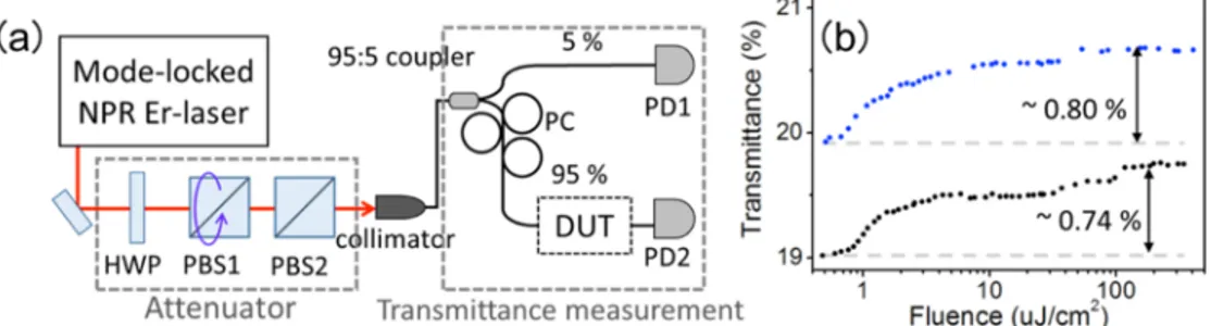
After the device fabrication, we measured the nonlinear transmittance (NLT) of the fiber-pigtailed PLC-CNT-SA. Figure 3(a) shows the schematic of NLT measurement setup. As the pulse source, a nonlinear polarization rotation (NPR)-mode-locked fiber laser with 400 fs pulse duration (measured at the input of DUT) is used. The input power to the DUT is controlled by rotating one polarization beam splitter (PBS1 in Fig. 3(a)). To measure the input and output power levels of DUT simultaneously and to compute the transmittance accurately, 95:5 fiber coupler and two photodetectors are used. A polarization controller is installed to control the input polarization to the DUT. Figure 3(b) shows the measured minimum and maximum NLT curves of the channel with 22-mm-long interaction length of the fabricated PLC-CNT-SA when changing the input polarization states. The polarization dependent loss (PDL) of the fabricated PLC-CNT-SA device is 0.2 dB. The measured NLT shows ~80% non-saturable loss and 0.74% - 0.80% modulation depth (depending on the input polarization state).
Fig. 3. (a) Nonlinear transmittance (NLT) measurement setup. HWP, half wave plate; PBS, polarization beam splitter; PC, polarization controller; DUT, device under test; PD, photodetector; (b) Measured nonlinear transmittance (NLT) curves of the channel with 22-mm-long interaction length in PLC-CNT-SA.
3. Application of the PLC-CNT-SA to high-repetition-rate all-fiber lasers
High-repetition-rate (e.g., higher than several hundreds MHz) mode-locked lasers at telecommunication wavelength are useful for many applications such as high-speed optical sampling and photonic analog-to-digital conversion [21], optical arbitrary waveform generation [22], frequency metrology [23], and fiber-link-based optical timing distribution [24]. As a result, various types of femtosecond Er-fiber lasers with higher than several hundreds MHz repetition-rates have been recently demonstrated [25–29]. The use of nonlinear polarization rotation (NPR) for mode-locking mechanism [25,26] enables short pulsewidth (~100 fs) and broad spectrum at repetition rates up to 464 MHz, however, this method requires free-space section and high (~1.5 W) pumping [25]. High-repetition-rate
fiber lasers mode-locked by SESAMs or ferrule-type transmittive SAs (using CNTs, graphene, and topological insulators) have been also demonstrated [27–29]. However, it has been known that reflective-type or ferrule-type SA devices are vulnerable to thermal damage and degradation issues in high-repetition-rate lasers. Therefore, due to the distributed field interaction nature, the use of evanescent-field-interacting SA devices can be a desirable approach for high-repetition-rate fiber lasers. As the first application of evanescent-field-interacting PLC-CNT-SA shown in Section 2, we demonstrate ~300-MHz repetition-rate, all-fiber, femtosecond Er ring lasers at 1550 nm.
3.1. 303-MHz-repetition-rate, soliton mode-locked, all-fiber Er-laser
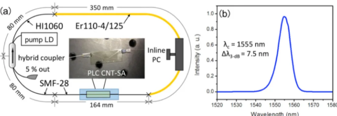
Figure 4(a) shows the schematic of a 303-MHz-repetition-rate, all-fiber Er-laser mode-locked by the PLC-CNT-SA. The demonstrated mode-locked fiber laser consists of Er-doped gain fiber (Liekki Er110-4/125), WDM/tap/isolator hybrid coupler (Haphit FHWT-09D05-B10), in-line polarization controller, and the fabricated PLC-CNT-SA. For optimization of the input polarization condition at the SA device, in-line polarization controller is used. The length of non-gain fiber sections are set to the minimum allowed by the used splicer machine (i.e., ~8 cm separation between device and splicing point). The gain fiber length of 35 cm is used, which is the minimum gain-fiber length that allows stable soliton mode-locking at ~1550 nm center wavelength. This fiber length combination results in repetition-rate of 303 MHz. The calculated net-cavity dispersion is about −2300 fs2 at 1555 nm, which supports stable soliton
mode-locking. Turn-key, self-starting operation could be obtained by increasing pump power. The measured output power from 5% output coupler is 0.5 mW when pumped by a 976-nm diode laser at 290 mW. Figure 4(b) shows the measured output optical spectrum. The FWHM spectral bandwidth at 1555 nm is measured to be 7.5 nm, which corresponds to 350-fs transform-limited pulse duration. Note that 311 MHz repetition-rate could be also achieved when the gain fiber is further reduced to 18 cm (while the non-gain fiber length is 49 cm), at the expense of shifted center wavelength to 1530 nm and reduced FWHM bandwidth of 5.4 nm (which corresponds to 530-fs transform-limited pulse duration).
To measure the pulse duration using interferometric autocorrelator (IAC), the oscillator output is amplified by an extra-cavity EDFA. The amplified pulse train delivers 76 mW (44 mW) average power when pumped at 750 mW (450 mW). Figure 5 shows the measured optical spectra and IAC traces. When pump power is set to 750 mW (450 mW), the measured optical spectrum shows 19 nm (12 nm) FWHM bandwidth and 209 fs (265 fs) retrieved FWHM pulse duration. Here the quoted pulse duration is determined by the Phase and Intensity from Correlation And Spectrum Only (PICASO) algorithm using the measured IAC trace and optical spectrum [30]. Note that the measured pulse duration amplified by external-cavity amplification is shorter than the transform-limited pulse duration of direct oscillator output because of the pulse compression by spectral broadening in a fiber amplifier with normal dispersion [31].
Fig. 4. (a) Schematic of the 303-MHz-repetition-rate all-fiber laser. (b) Measured optical spectrum of oscillator output.
Fig. 5. (a) Measured optical spectra of amplified output with different pump power conditions for the external-cavity EDFA (450 mW and 750 mW). (b,c) Measured IAC trace when the EDFA pump power is set to 450 mW and 750 mW, respectively.
Figure 6(a) shows the measured 1-MHz-span radio-frequency (RF) spectrum of the 303-MHz-repetition-rate laser oscillator output with 1-kHz resolution bandwidth. The measured fundamental repetition-rate of the laser is 302.65 MHz with a signal-to-noise ratio (SNR) of 68 dB. Figure 6(b) shows the broadband RF spectrum with 100-kHz resolution bandwidth. We also measured relative intensity noise (RIN) spectrum of the oscillator output as shown in Fig. 6(c). Note that the measured RIN spectrum above 20 MHz offset frequency is limited by the photodetector noise floor. The rms RIN integrated from 10 Hz to 100 kHz (10 MHz) offset frequency is only 0.032% (0.078%), which is a similar level compared with the RIN of the recently demonstrated femtosecond-jitter CNT-mode-locked all-fiber soliton Er-laser [32].
Fig. 6. (a) Measured RF spectrum (1-kHz resolution bandwidth, 1-MHz span). (b) Measured RF spectrum (100-kHz resolution bandwidth, 3-GHz span). (c) Measured relative intensity noise (RIN) spectrum.
3.2. 274-MHz-repetition-rate, stretched-pulse mode-locked, all-fiber Er-laser
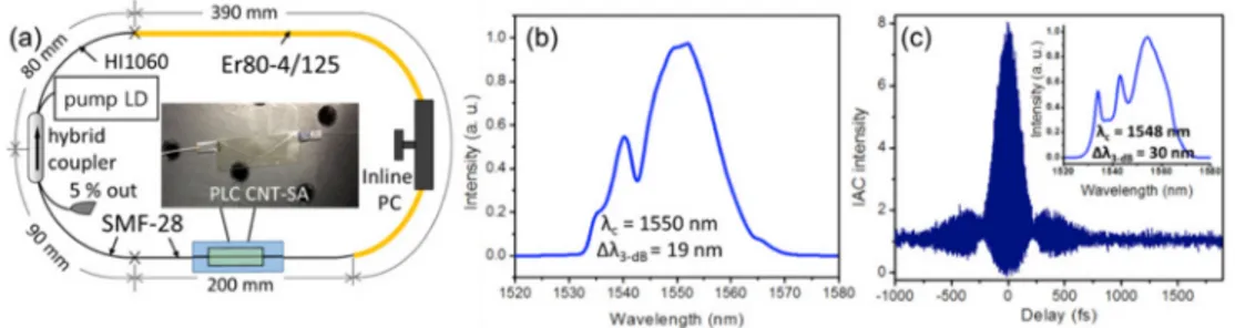
In addition to the soliton mode-locked laser shown in Section 3.1, we modified the laser oscillator to operate it in the stretched-pulse regime. Figure 7(a) shows the schematic of the implemented 274-MHz-repetition-rate, stretched-pulse mode-locked laser. In order to shift the net-cavity dispersion to close-to-zero, the gain fiber is replaced with the one with higher anomalous dispersion (Liekki Er80-4/125 with + 19 fs2/mm dispersion). The resulting
net-cavity dispersion of the final design is about + 180 fs2. Note that stretched-pulse operation
generally requires higher modulation depth than soliton operation, and we believe that additional NPR in the fiber oscillator might have increased the effective modulation depth of the PLC-CNT-SA by experiencing different NLT curves for different fluence in the pulse (which requires further experimental investigation in the future). Figure 7(b) shows the measured optical spectrum at the oscillator output. The measured FWHM spectral bandwidth is 19 nm centered at 1550 nm, which corresponds to 215-fs FWHM transform-limited pulse duration. Due to the stretched-pulse operation, the FWHM bandwidth is about three times broader than that of 303-MHz solition laser. The oscillator output power from 5% output coupler is 0.64 mW when pumped at 290 mW. To characterize the pulse duration, extra-cavity EDFA is again employed to amplify the output from the oscillator. The output optical pulse train is amplified to 71 mW when EDFA pump power is set at 650 mW. Figure 7(c) shows the measured IAC trace and the optical spectrum of the amplified optical pulse train. The measured optical spectrum shows 30 nm FWHM bandwidth centered at 1548 nm. The retrieved FWHM pulse duration is 178 fs when using the PICASO algorithm.
Fig. 7. (a) Schematic of the 274-MHz-repetition-rate, stretched-pulse, all-fiber laser. (b) Measured optical spectrum of the oscillator output. (c) Measured IAC trace and optical spectrum of amplified optical pulse train.
Fig. 8. (a) Measured RF spectrum (1-kHz resolution bandwidth, 1-MHz span). (b) Measured RF spectrum (100-kHz resolution bandwidth, 3-GHz span). (c) Measured relative intensity noise (RIN) spectrum.
Figure 8(a) shows the measured RF spectrum of the stretched-pulse fiber laser with 1-kHz resolution bandwidth and 1-MHz span. The measured fundamental repetition-rate is 274 MHz with SNR of 70 dB. Figure 8(b) shows the broadband RF spectrum with 3-GHz span and 100 kHz resolution bandwidth, which shows clean fundamental mode-locking. The measured RIN
spectrum is shown in Fig. 8(c). The rms RIN integrated from 10 Hz to 100 kHz (10 MHz) is 0.026% (0.062%), which is similar to the RIN of the 303-MHz soliton laser.
4. Summary and outlooks
In this work, we show a fully streamlined process of producing fiber-pigtailed, evanescent-field-interacting SAs using PLC fabrication technology. The implemented PLC-CNT-SA device is further applied to realize self-starting, high-repetition-rate, all-fiber ring oscillators, which results in a repetition-rate up to 311 MHz. A soliton-mode-locked, all-fiber Er laser is demonstrated with 303 MHz repetition-rate and 7.5 nm FWHM spectral bandwidth at 1555 nm center wavelength. A stretched-pulse operation with 274 MHz repetition-rate and 19 nm FWHM spectral bandwidth is also demonstrated. When amplified by an extra-cavity EDFA, thanks to the pulse compression in a normal-dispersion fiber amplifier, the resulting FWHM bandwidth/pulse duration become 19 nm/209 fs and 30 nm/178 fs for 303-MHz soliton and 274-MHz stretched-pulse lasers, respectively. To our knowledge, these results correspond to the highest repetition-rates for femtosecond fiber lasers mode-locked by evanescent-field-interaction-type SAs. The current repetition-rates are mostly limited by large non-saturable loss of the SA device (~80%), which nessecitates longer gain fibers, and the required minimum lead length for fiber splicing. By reducing the non-saturable loss of SAs (with more optimized waveguide geometry and/or using different SA materials) and using a better fiber splicing machine, we anticipate that the repetition-rate of all-fiber ring oscillators can be scaled up to >500 MHz.
The demonstrated SA fabrication method based on well-established PLC processes for producing commercial fiber-optic communication devices shows a new direction for development of mass-producible and low-cost waveguide-type SA devices applicable for fiber and waveguide lasers. We are currently working on adding more functionalities to the PLC-SA chip, such as WDM couplers, directional couplers and loop-mirrors, to enable new types of compact, lower-cost, and self-starting fiber and waveguide lasers.
Acknowledgments
This research was supported by the National Research Foundation (NRF) of South Korea (grant 2013M1A3A3A02042273) and KAIST End-Run Business Development Project. D.-I.Y. acknowledges support from the National Research Foundation (NRF) of South Korea (grant 2013R1A1A2A10005230); F.R. acknowledges support from the National Research Foundation (NRF) of South Korea (grant 2011-0017494).