한국정밀공학회 2013 년도 춘계학술대회논문집 1. 서론 전단가공은 펀치와 다이가 서로 맞물려 닫 혀짐으로써 재료에 전단력을 가해 재료를 잘라 내는 방법을 일컫는다. 이와 같은 가공방법은 일반적으로 알려진 바와 같이 공정이 단순하다 는 장점이 있지만 펀치와 다이 사이의 간극, 곡률반지름으로 인하여 공정시 버(Burr)가 발생 한다는 단점을 가지고 있다(1). 이는 제품의 품 질을 떨어뜨리고 불량의 원인이 되며 후가공이 발생되어 제품 단가를 상승시키는 요인이 된다. 때문에 버의 발생을 최소화 할 수 있는 전단공 정의 최적 설계가 필요하다. (a) (b) (c) Fig. 1 Cross section of each part
Fig.1 은 일반적인 전단가공방법을 이용하여 제조된 자동차 클러스터 계기명판이다. (a), (b), (c) 의 단면을 측정한 결과, 파단면(lf)의 길이가 전단면(ls)의 길이에 비하여 크고 불량률의 가 장 큰 요인이 되는 버(lb)가 상당량 발생하는 것을 확인할 수 있다. 2. 전단공정 설계 펀치 형상 및 간극, 곡률 반지름이 제품의 성형성 및 불량 발생에 미치는 영향을 파악하 기 위하여 유한 요소 해석을 실시하였다. 클러 스터 계기명판의 전단 가공 해석에 사용된 재 료는 CCL500 이며 DEFORM-2D 를 이용하여 2 차원 해석을 수행하였다.
(a) Model (b) Each part size Fig. 2 Model and each part size
(a)R:2%,C:2% (b)R:2%,C:5% (c)R:5%,C:5% Fig. 3 FEM result according to each condition (R : Round, C : Clearance)
유한요소해석을 이용한 자동차 계기명판 전단공정 설계
A Shearing Process Design for a Dial Panel of Automotive Using
Finite Element Analysis
*윤정환1,2, #정명식1, 이상곤1, 성지현1, 김강은1, 김양곤1, 김다혜1
*J. H. Yun1,2, #M. S. Jeong([email protected])1 , S. K. Lee1, J. H. Sung1, K. E. Kim1, Y. K. Kim1, D. H. Kim1
1한국생산기술연구원 대경권지역본부 녹색전환기술센터, 2경북대학교 기계공학과 대학원
Key words : FE-simulation, Shearing, Burr, Angle punch, Process design, Blanking
한국정밀공학회 2013 년도 춘계학술대회논문집 간극과 곡률 반지름은 재료의 두께에 대비 하여 각각 2%, 5% 두 조건으로 설정 하였으며, Fig. 2 는 해석조건을 나타낸다. 유한요소해석 결과 Fig. 3 과 같이 펀치의 간극과 곡률 반지름이 작을수록 버의 길이가 작아지는 것을 확인 할 수 있다. 이는 재료에 국부적인 응력집중현상이 발생할 때, 큰 전단 력이 작용하게 되는 것으로 설명할 수 있다. 따라서 전단 가공시 재료에 큰 전단력이 작용 할 수 있도록 Fig. 4 의 형상 및 조건으로 펀치 를 수정하고 유한요소해석을 재수행 하였다.
(a) Model (b) Each part size Fig. 4 Model and each part size
Fig. 5 는 수정된 펀치를 적용한 전단 해석 결과이다. Fig. 2 의 형상 및 해석조건을 적용한 경우와는 응력분포가 서로 다른 것을 확인할 수 있다. 또한 동일 조건에서의 버 발생이 줄 어드는 것을 확인할 수 있었다(Fig. 6). (a)R:2%,C:2% (b)R:2%,C:5% (c)R:5%,C:5% Fig. 5 FEM result at using a acute angle punch(R : Round, C : Clearance)
(a)Flat punch (b) Acute angle punch Fig. 6 Comparison of both conditions
3. 전단가공 공정 실험 Fig. 7 은 유한 요소 해석을 통해 얻은 결과 를 이용하여 버의 발생을 최소화 하기 위한 형 태의 펀치를 제작한 것이다. 제작된 펀치를 사 용하여 전단 가공 공정을 수행하였을 때, 과도 한 굽힘(Shear drop)이나 미전단 등의 결함은 발 생하지 않았다.
Fig. 7 Acute punch and die
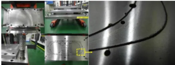
또한 Fig. 8 과 같이 버가 현저하게 줄어드 는 것을 확인할 수 있었으며 이는 기존 가공방 법으로 전단가공을 수행했을 때보다 약 17%의 불량률 감소효과를 나타내었다.
Fig. 8 Reduction in the length of the Burr
4. 결론 본 연구에서는 전단공정시 성형에 영향을 미치는 인자들에 대하여 분석하였다. 그 결과 펀치가 예각의 형상을 가지며 간극과 곡률 이 작아질 수록 전단면이 길어지고 버가 감소함을 확인할 수 있었다. 참고문헌
1. J. Y. Kim, J. H. Kim, W. J. Chung., “Influence of Die Design Variables on the Sheared Surface in Shearing Process of Sandwich Sheet Metal,” Journal of Materials Processing Technology, Vol. 14, 2005.