A Fast Guide Tube Position Estimation Algorithm
for a Control Rod Support Pin Inspection Robot
Jae C. Lee, Hyeong S. Jeon, Yu R. Choi, Jae H. Kim
Korea Atomic Energy Research Institute, 150.Duckjin dong, Yusong gu, Taejon, [email protected]
1. Introduction
The risk that PWR guide tube support pins will crack has increased the necessity for the development of inspection methods and equipment.[1] A special remote-controlled manipulator has been widely used to inspect the guide tube support pins. We presented a matched filter algorithm for detecting the existence and estimating the position of the guide tube support pins.[2][3] But, the matched filter algorithm requires numbers of complex floating point calculations for the 2-D FFT and therefore it can not be fitted in to the small-sized embedded processors. We proposed a new simplified method for estimating the position of the guide tube support pins. It uses most of the operations with integers. We ported the proposed method in intel’s xscale processor running at 400mhz. We used gnu C language in embedded linux operating system. We can calculate the algorithm at a rate of 20frames/sec. in a 160*120 image size.
2. Method and Result
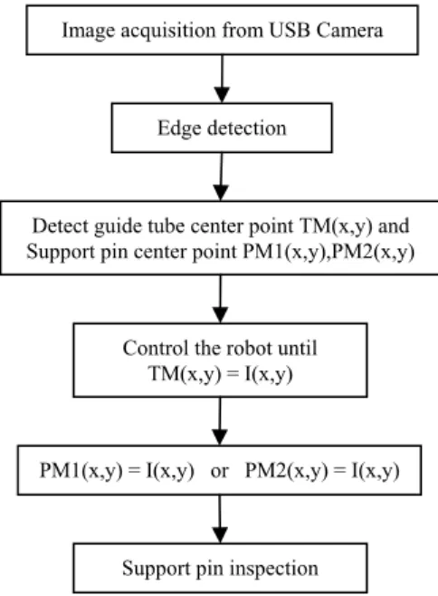
There are many researches for controlling a robot with camera images.[4][5][6] We have depicted a flowchart of our method in figure 1.
Figure 1. Guide tube and support pin position tracking algorithm
2.1 Edge detection
We use a USB camera and take the image size of 160*120 at the rate of 20 frames/sec. We used the famous sobel’s operator for an edge detection. And then, we applied the appropriate threshold to the original image and converted it to a binary valued image as in figure 2 (b).
(a) (b)
Figure 2. Control rod support pin (a) Original image (b) Binary valued edge image
2.2 Find Guide tube’s center point and support pin’s center point
Figure 3 shows the variables and coordinates for the guide tube’s and support pin’s center point detection in a binary valued image. First, we searched the U, D, L, R.
Figure 3. U, D, L, R point search in 320*240 edge image
We treat the 2-D image as 1-D sequential data for a fast evaluation of the searching algorithm. We can find the coordinates of x, y as (1).
U(xU,yU) -> xU=U%width , yU=U/width D(xD,yD) -> xD=D%width , yD=D/width L(xL,yL) -> xL=L%width , yL=L/width
R(xR,yR) -> xR=R%width , yR=R/width (1)
y x
Image acquisition from USB Camera
Edge detection
Detect guide tube center point TM(x,y) and Support pin center point PM1(x,y),PM2(x,y)
Control the robot until TM(x,y) = I(x,y)
PM1(x,y) = I(x,y) or PM2(x,y) = I(x,y)
Support pin inspection
Transactions of the Korean Nuclear Society Autumn Meeting Busan, Korea, October 27-28, 2005
Where, U is the index of that corresponding to U at the 1-D sequential image data and D,R,L are those corresponding to D,R,L respectively. And ‘%’ means the modulo operation, ‘/’ means the integer division and width is the width of the image.
Next, the center coordinate of the guide tube is obtained as follows.
xTM= (xL+xR)/2,
yTM=(yU+yD)/2 (2)
There are two support pins per each guide tube therefore we define their center coordinates as follows.
PM1(xPM1,yPM1), PM2(xPM2,yPM2)
And we discriminate the two support pins as follows.
If((xR - xL) > ( yU - yD))
PM1(xL+r,yL), PM2(xR-r,yR)
else
PM1(xU,yU-r), PM2(xD,yD+r) (3)
Where, r is the radius of the support pin. And upper is the case for two support pins horizontally aligned and lower is the case for two support pins vertically aligned. We can obtain the center coordinates of a guide tube and the two support pins by (1)(2)(3).
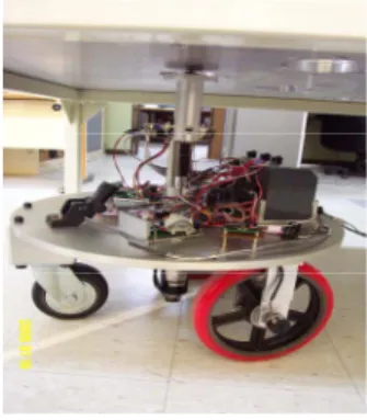
We applied the proposed method to the guide tube support pin’s inspection robot.
Figure 4. Experience in our lab.
3. Conclusion
We used a video image for a control of the support pin’s inspection robot. We proposed a simple integer based guide tube and a support pin search algorithm that could be ported into a small-sized embedded processor. Our method is efficient and operated on a real-time for today’s high-end embedded processor. But there are some problems such as its too sensitive at the light noise and an undetermined result in the case of two support pins aligned vertical.
REFERENCES
[1] J. Gustafsson, Inspecting Guide Tube Support Pins in Swedish PWRS, Nuclear Engineering International, 1985. [2] J. C. Lee A Fast Position Estimation Method for a Control Rod Guide Tube Inspection Robot with a Single Camera, Proc. Of the Korean Nuclear Society Autumn Meeting Youngpyong, p. 643, Oct. 2004,
[3] J.C. Lee, A Position Estimation Method of the Control rod Guide Tube with Matched Filters, Proc. Of the Korean nuclear Society Spring Meeting Jeju, p. 643, . 2005
[4] Don Murray, Anup Basu, Motion Tracking with an Active Camera,IEEE Transactions on Pattern Analysis and Machine Intelligence,vol.16, no.5 May 1994
[5] 1999.Naohiro Amamoto and Akihiro Fujii, Detecting Obstructions and Tracking Moving Objects by Image Processing Technique ,Electronics and Communications in Japan, Part 3, Vol. 82, No. 11,1999
[6] OpenCV. Opencv Source Computer Vision Library. http://www.intel.com/research/mrl/research/opencv/